Dynamic R1 PRO User manual

DYNAMIC R1 PRO
21S FITNESS CYCLE
OWNER’S MANUAL

Dear customer,
Thank you for purchasing the DYNAMIC R1 PRO 21S Fitness Cycle. This product was
designed to meet your workout and fitness needs and provide you with a healthier life.
Before you begin using this product, please read the Owner’s Manual completely, thoroughly,
and follow the instructions precisely paying close attention to all WARNING and CAUTION
labels. Always consult your physician before beginning use of new exercising equipment.
If you have any questions about this product or are in need of replacement parts, please
contact Customer Service by calling (909) 212-5555 or emailing us at:
info@goldendesignsinc.com
____________________________________________________________
TABLE OF CONTENTS
WARNING & CAUTION LABELS…..…………………….……….………………………..….………. P.1
SAFETY INSTRUCTIONS…………………………………….……………………………..…………. P.2
PARTS LIST.……………………………………………………………………………………..………. P.3
EXPLODED DRAWING.……………………………………………….………………………..………. P.4
PACKING PARTS LIST………………...…………..…………………..……………………………….. P.5
ASSEMBLY ………………………………………....…………………………………….…….…..…… P.6
HOW TO USE THE BIKE ……………………….………………………. ………………….…………. P.9
COMPUTER CONSOLE ……………………….…………..…………. ……………………………… P.10
SERIAL NUMBER LABEL…….…………..………..……….…………………………………………. P.12
WARRANTY ………………………..……………..………….…………………………………………. P.13
____________________________________________________________
WARNING & CAUTION LABELS
The diagram below shows the locations of the WARNING and CAUTION labels. Please
note the locations of these labels and carefully follow the instructions as described.
(Note: The labels shown below are not of actual size.)
1

SAFETY INSTRUCTIONS
Before you start to assemble and operate this product, please carefully read the Owner’s
Manual in its entirety. Please follow all instructions in this Owner’s Manual as described.
Be sure to read through the Safety Instructions below and keep this Owner’s Manual for
future reference.
●Misuse of this product may cause serious injury.
●Consult your physician before starting any exercise program.
Please follow your physician’s advice on fitness training.
●Please follow all warnings, cautions, and instructions carefully while using this product.
●Only use original parts (except personal saddle) accompanying this product.
●This product is designed for adult use only.
Do not allow children to use this product or be around this product when in use.
●The maximum user's weight is 265lbs / 120kgs.
●Place this product on an even, non-slippery surface.
Keep this product away from dust. Avoid placing and using this product in a damp
environment.
Please wear appropriate sports clothing while exercising.
Do not wear loose clothes that could become caught on the bike.
Please wear appropriate sports shoes for foot protection.
●To stop, reduce your pedal speed and pull the tension lever to BRAKE.
It is not recommended to stop by discontinuing pedaling motion as that can cause
serious injury.
●This product is not intended for therapeutic use.
●Inspect product components every 1-2 months to ensure levers and connections are
snug and tight for safe operation. Replace any worn parts immediately.
2

PARTS LIST
Item
Description
Quantity
Item
Description
Quantity
1
Main Frame
1
46
Inner Chain Cover
1
2
Rear Foot Bar
1
47
Screw
2
3
Front Foot Bar
1
48
Belt
1
4
U-Mone Bar
1
49
Belt Deck
1
5
Seat Post
1
50
Screw
4
6
Handle Post
1
51
Outer Chain Cover
1
7
Seat Slider
1
52
Round Head Screw
6
8
Handle Bar
1
53
Left Crank
1
9
End Cap
2
54
Right Crank
1
10
Adjustable Pad
2
55
Left Pedal
1
11
Move Wheel
2
56
Right Pedal
1
12
Hex Head Bolt
2
57
Bolt
2
13
Nylon Nut
2
58
Cap
2
14
Washer
4
59
Plug
2
15
Hex Head Bolt
4
60
Knob
4
16
Cap Nut
2
61
Flat Washer
2
17
End Cap
2
62
Seat
1
18
Bearing
2
63
Round Head Bolt
2
19
Bearing
2
64
End Cap
1
20
S Nut
1
65
Washer
2
21
Belt Wheel Rod
1
66
Spanner
1
22
Left Cover
1
67
Spanner
1
23
Right Cover
1
68
Washer
2
24
Computer
1
69
Nut
2
25
Bracket
1
70
Foam Pad
2
26
Rear Cover
1
71
Bracket
1
27
Front Left Cover
1
72
Bolt
1
28
Front Right Cover
1
73
Nut
1
29
Screw
1
74
Washer
1
30
Screw
1
75
Hand Pulse sensor chip
2
31
Screw
2
76
Hex wrench
1
32
Screw
2
77
The stopper
2
33
Tapping Screw
2
78
Nuts
2
34
Tapping Screw
2
79
Chain cover piece
1
35
Flywheel
1
80
Screw
1
36
Belt Wheel
1
81
Screw
1
37
Fly Wheel Rod
1
82
Sensor
1
38
Spring Washer
2
83
Roll sensor line
1
39
Nut
2
84
Bottle frame screws
1
40
Adjustable Bolt
2
85
Bottle
1
41
Lock Nut
2
86
Adjustment knob
1
42
Brake Pad
2
87
Table frame nut
1
43
Stopper Set
1
44
Stopper Bar
1
45
Screw
2
3

EXPLODED DRAWING
4

____________________________________________________________
PACKING PARTS LIST
5

___________________________________________________________
ASSEMBLY
●Read the Owner’s Manual in its entirety before assembly.
●Remove all parts from the box.
●Check to confirm receipt of all parts and quantities shown in the Packing Parts List on
page 5.
(Note: Some parts may be pre-assembled.)
STEP 1
Slide the Rear Foot Bar (2) to the rear of the Main
Frame (1) adding two Washers (14) and two Hex
Head Bolts (15) as shown in Figure 1.
** Tighten all bolts used in STEP 1 with the
Spanner Tool (66).
STEP 2
Slide the Front Foot Bar (3) to the front of the
Main Frame (1) adding two Washers (14), two
Spring Washers (68), two Cap Nuts (16), and two
Hex Head Bolts (15) as shown in Figure 1.
** Tighten all bolts used in STEP 2 with the two
Spanner Tools (66) & (67).
** You can use the Styrofoam (inner packing
material) as a support to keep the Front Foot
Bar (3) higher for easier tightening of the
bolts and nuts.
STEP 3
Insert the U-Zone Bar (4) into the holes of the
Front Foot Bar (3) adding two Washers (65)
and two Round Head Bolts (63) as shown in
Figure 1.
** Tighten all bolts used in STEP 3 with the
Spanner Tool (66).
6

____________________________________________________________
ASSEMBLY
STEP 4
Attach the Left Pedal (55) and Right Pedal (56) to
the Left Crank (53) and Right Crank (54) as
shown in Figure 2.
** Tighten the Left & Right Pedals used in
STEP 4 with the Spanner Tool (67).
STEP 5
Insert the Seat Post (5) into the tube of the Main
Frame (1) with Knob (60) as shown in Figure 3.
** Hand tighten ONLY.
STEP 6
Affix the Seat (62) on the bar of the Seat Slider (7).
Next, slide this set onto the Seat Post (5) with Flat
Washer (61) and Knob (60) and then tighten as
shown in Figure 3.
** Hand tighten ONLY.
7

____________________________________________________________
ASSEMBLY
STEP 7
Attach the Handle Bar (8) onto the Handle Post (6)
with one Flat Washer (61) and Knob (60) as
shown in Figure 4.
** Hand tighten ONLY.
STEP 8
Insert the Handle Post (6) into the tube of the Main
Frame (1) with Knob (60) as shown in Figure 4.
** Hand tighten ONLY.
STEP 9
Affix the Bracket (25) on the Handle Bar (8) with
screw (81) and Table frame nut (87).
IMPORTANT NOTE:
Please make sure all Screws, Nuts, Bolts,
Pedals and Seat are tightened in correct
position.
Product Assembly Size: 66.9”x25.6”x50.4”
8

HOW TO USE THE BIKE
After assembling the bike and tightening all appropriate components as instructed, you can
now begin using bike. Handle bar, seat, and elbow pad adjustments allow users to adjust
the bike to fit one's size and body frame. Streamline surface design fits in with ergonomics
and increases comfort.
●HANDLEBAR ADJUSTMENT
(1) Forward/Backward:
Loosen the knob (60) on the handle post (6), slide the handle bar (8) forward or
backward and tighten the knob (60) to lock the handle bar (8) into position.
(2) Up/Down:
Loosen the knob (60) on the main frame (1), slide the handle post (6) up or down
and tighten the knob (60) to lock the handle bar (8) into position.
●SEAT ADJUSTMENT
(1) Forward/Backward:
Loosen the knob (60) on the seat post (5), slide the seat slider (7) forward or
backward and tighten the knob (60) to lock the seat (62) into position.
(2) Up/Down:
Loosen the knob (60) on the main frame (1), slide the seat post (5) up or down and
tighten the knob (60) to lock the seat (62) into position.
●SEAT REPLACEMENT
The included seat (62) meets the standard specifications for this bike and can easily be
adjusted and removed. This seat is interchangeable with your own seat for added
personal comfort.
●ELBOW PAD ADJUSTMENT
The movable elbow pad (70) design offers users different options for adjustable elbow
positioning. There are two holes on either side of the handle bar (8) for elbow pad (70)
adjustments. You can choose the hole which is suitable for your body type and tighten
the elbow pad (70) onto the handle bar (8).
●TENSION LEVEL ADJUSTMENT
This bike allows you to burn more calories at the lower tension levels. The different
levels provide you with options to extend your workout and increase muscle tone.
The Micro Tension Switch offers the micro adjustments of the resistance for users to
train their body gradually. Minus (-) is the lower tension level ; Plus (+) is the higher
tension level.
●WATER BOTTLE & WATER BOTTLE HOLDER
The water bottle holder can be mounted anywhere of the Handle Bar (8). You can install
the water bottle holder at your discretion for added convenience.
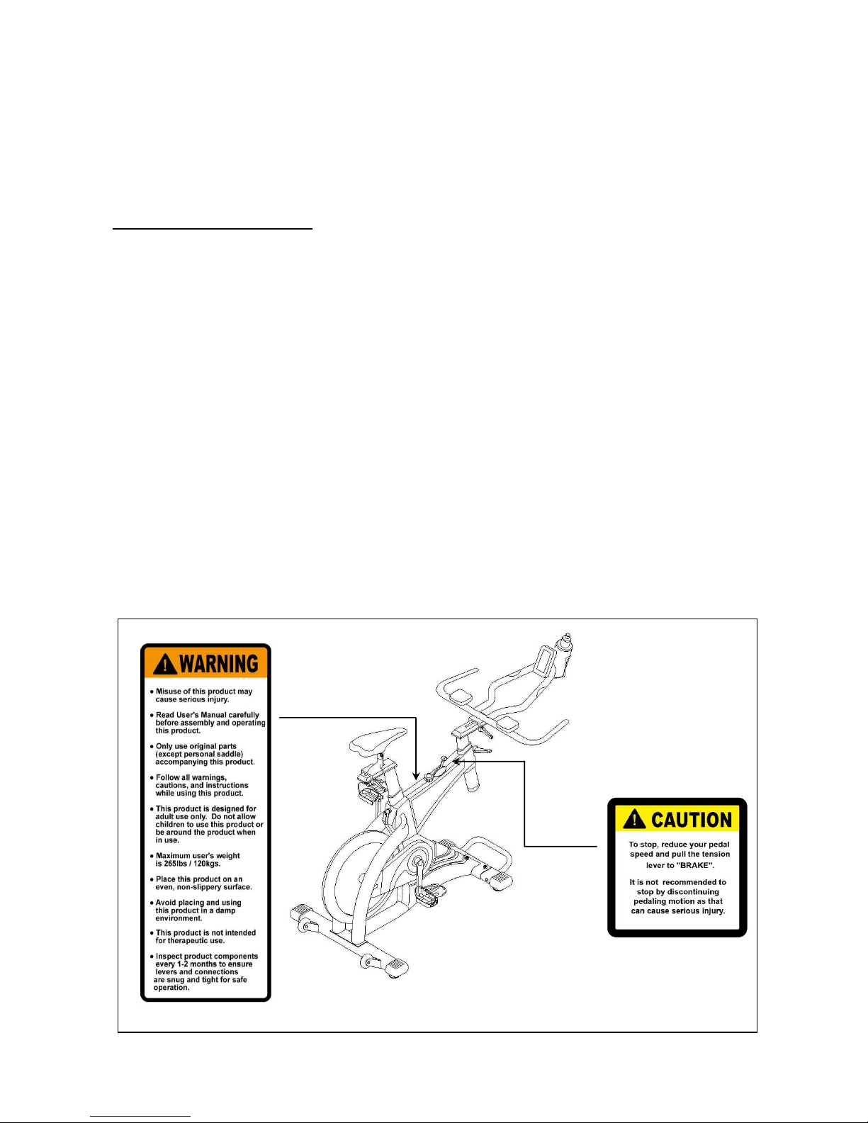
●STOP / BREAK
If you want to stop, reduce your pedal speed and pull the tension lever to “BRAKE”. It’s
not recommended to stop by discontinuing pedaling motion as that can cause serious
injury.
●WHEN BIKE IS NOT IN USE
When the bike is not in use, set the tension lever to “BRAKE”to prevent the flywheel
from moving.
9

COMPUTER CONSOLE
(computer console subject to change)
How to change battery﹕
1. Open battery cover and insert two AAA batteries.
2. Properly replace the back battery cover.
3. Under normal circumstances, the life of the battery is approximately one year.
4. If the LCD shows a partial display, please remove the batteries, wait for 15 seconds, and then
re-insert the batteries. Please Note: all setting will be lost once the batteries have been removed.
5. Please follow local safety guidelines for the disposal of batteries.
Function Keys﹕
ENTER:1. Press the ENTER key to select the functions for setting exercise values for TIME
and DISTANCE.
2. Press the ENTER key to confirm the set exercise values.
3. Keep pressing the ENTER key for 2 seconds to remove all previous exercise
data.
UP:1.Press the UP key to switch between the functions of speed, average speed,
maximum speed, heart rate, maximum heart rate, RPM, average RPM and
maximum RPM.
2. Press the UP key to add the setting exercise values of TIME and DISTANCE. The
minimum setting value of TIME is 5 minutes. Pressing one time will add 5
minutes, for example: 0, 10, 15, 20, …..
DOWN:1. Press the DOWN key to switch between the SPEED DISTANCE and
CAL PULSE.
2. Press the DOWN key to decrease the setting exercise values of TIME and
DISTANCE. The minimum setting value of DISTANCE is 1 km or mile.
Pressing one time will decrease 1 km or mile, for example : 7, 6, 5, 4, 3, 2,
1…
UP+DOWN:1. Press the UP key and the DOWN key at the same time for 3 seconds to start
the “AUTO SCAN”function.
2. Under the condition of setting exercise values, Press UP key and DOWN
key at the same time for 1 second to remove the values.
10

Function and Operation
Auto ON/OFF
The monitor automatically starts working once the user starts to do the exercise on the
machine. It will automatically turn off after the machine is not used for 4 minutes. Once
it turns off, all exercise values will be removed.
TIME
1. Press the ENTER key to select TIME. Then press the UP/DOWN keys to set the
exercise TIME.
2. If users do not set the TIME, the time will automatically count up 00:00:00~99:59:59
3. Setting the value of the countdown will be from 5:00~99:55:00. The monitor will beep
when the countdown reaches 0:00.
SPEED
1. SPEED display range is 0.0 ~ 99.9 KPH / MPH
2. 3 SPEED display: current speed, average speed, and maximum speed.
RPM
1. RPM display range is 15 ~ 999.
2. 3 RPM display: current RPM, average RPM, and maximum RPM.
DISTANCE
1. Press the ENTER key to select DISTANCE (TIME value is 0), and press the UP/DOWN
keys to set the exercise value.
2. If users do not set the DISTANCE, the distance will automatically count up 0.0~999.9
km/mile.
3. Setting the value of the countdown is from 1.0~999.0 km/mile. The monitor will beep when
countdown to 0:00.
CALORIE
1. Calorie displays K/Cal on the LCD.
2. Calorie: will automatically count up 0.0~9999
PULSE
1. Pulse display range is 40~200. The Pulse value will display “P”after user stops measuring
heart rate for 16 seconds.
2. PULSE: displays “BPM” on the LCD.
3. 3 PULSE display: current heart rate, average heart rate, and maximum heart rate.
Attention︰
Recommended Working Temperature︰0℃~ 50℃
Recommended Storage Temperature.︰-10℃~ 60℃
11

____________________________________________________________
SERIAL NUMBER LABEL
The diagram below shows the location of the Serial Number Label. The serial number is
indicated on the label affixed to the lower part of the Main Frame.
(Note: The label shown below is not of actual size.)
12

WARRANTY
This Limited Warranty applies in the United States and Canada to products distributed
under the DYNAMIC brand name. This warranty extends only to the original purchaser
and stands at one (1) year from the date of purchase. This warranty is not transferable
to anyone who subsequently purchases the product from the original purchaser.
During the warranty period, DYNAMIC has the option to replace or repair a part(s) that
was discovered damaged or has become damaged due to a manufacturer defect only,
and may be done so with serviceable used parts that are equivalent to the new parts in
performance. This warranty does not cover: faulty set up procedures, assembly errors,
alterations, modifications, misuse, abuse, accidents, improper maintenance, damage
or malfunctions caused by moving or dropping of the product, unforeseen home
damage, acts of nature, or repairs not provided by DYNAMIC customer service.
Questions to determine the validity of a defect claim may be done by a DYNAMIC
service technician. DYNAMIC reserves the right to change manufacturers of any part(s)
to cover any existing warranty. To obtain warranty parts, you must contact customer
service (see page 1). Any evidence of alteration or misuse will be cause for immediate
void of this Limited Warranty. This warranty does not extend to any product not
purchased from an authorized reseller or dealer. Product on which the serial number
has been altered, defected, or removed is not eligible for warranty service.
Golden Designs, Inc. and DYNAMIC make no other warranties, expressed or implied,
including any implied warranties or merchantability and fitness for a particular purpose.
DYNAMIC expressly claims all warranties not stated in this Limited Warranty. Neither
DYNAMIC nor any of its affiliates shall be responsible for incidental or consequential
damages or costs.
Golden Designs, Inc. and DYNAMIC shall not be liable for loss of use of the exercise
equipment or other Golden Designs, Inc. products or other secondary or incidental or
consequential costs, expense or damages arising directly or indirectly out of the use or
inability to use the product. Under no circumstances shall Golden Designs, Inc. or any of
its representatives or affiliates be held liable for injury to any person or damage to any
property, however arising. Specifications are subject to change without notice or
obligation. This limited warranty gives you specific legal rights. You may have other
rights, which may vary from state to state and/or country to country.
13
Table of contents