ITEM
NO. PCS.
REQ’D DESCRIPTION
2-80000-29
SERIES
PART NO.
4-80000-29
SERIES
PART NO.
6-80000-32
SERIES
PART NO.
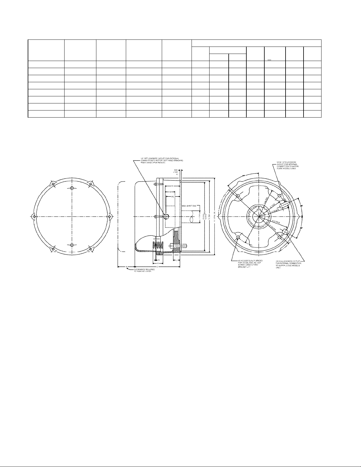
11Hub
21Bracket W/Studs –1Disc H080105-001
21Bracket W/Studs –2 Disc H080105-002
21Bracket W/Studs –3 Disc H080105-003
21Bracket W/Studs –4 Disc H080105-004
21Bracket W/Studs –5 Disc H080105-005
2a 1Bracket W/High Tensile Studs –1 Disc H080105-006
2a 1Bracket W/High Tensile Studs –2 Disc H080105-007
2a 1Bracket W/High Tensile Studs –3 Disc H080105-008
2a 1Bracket W/High Tensile Studs –4 Disc H080105-009
2a 1Bracket W/High Tensile Studs –5 Disc H080105-010
34Stud –1 Disc G070213-001
34Stud –2 Disc G070213-002
34Stud –3 Disc G070213-003
34Stud –4 Disc G070213-004
34Stud –5 Disc G070213-005
3a 4Stud –1 Disc High Tensile G070219-001
3a 4Stud –2 Disc High Tensile G070219-002
3a 4Stud –3 Disc High Tensile G070219-003
3a 4Stud –4 Disc High Tensile G070219-004
3a 4Stud –5 Disc High Tensile G070219-005
4(1) Rotating Friction Disc H080002-002
4a (1) Heavy Duty Rotating Friction Disc (Alt.) H080026-003
5(2) Stationary Disc K080179-001
61Pressure Plate K080072-001
74Torque Spring (25, 50, 75 Lb. Ft.) G070011-001
74Torque Spring (35, 70,105,125,175 Lb. Ft.) G070019-001
84Torque Spring Washer W004004-001
94Torque Adjusting Nut W003001-022
10 2Manual Release Rod G070001-002
11 2Manual Release Spring G060010-001
12 2Manual Release Washer W004004-003
13 As Req’d Manual Release Shim W004004-004
14 2Manual Release Stop Screw G060029-001
15 2Manual Release Lockwasher W004007-007
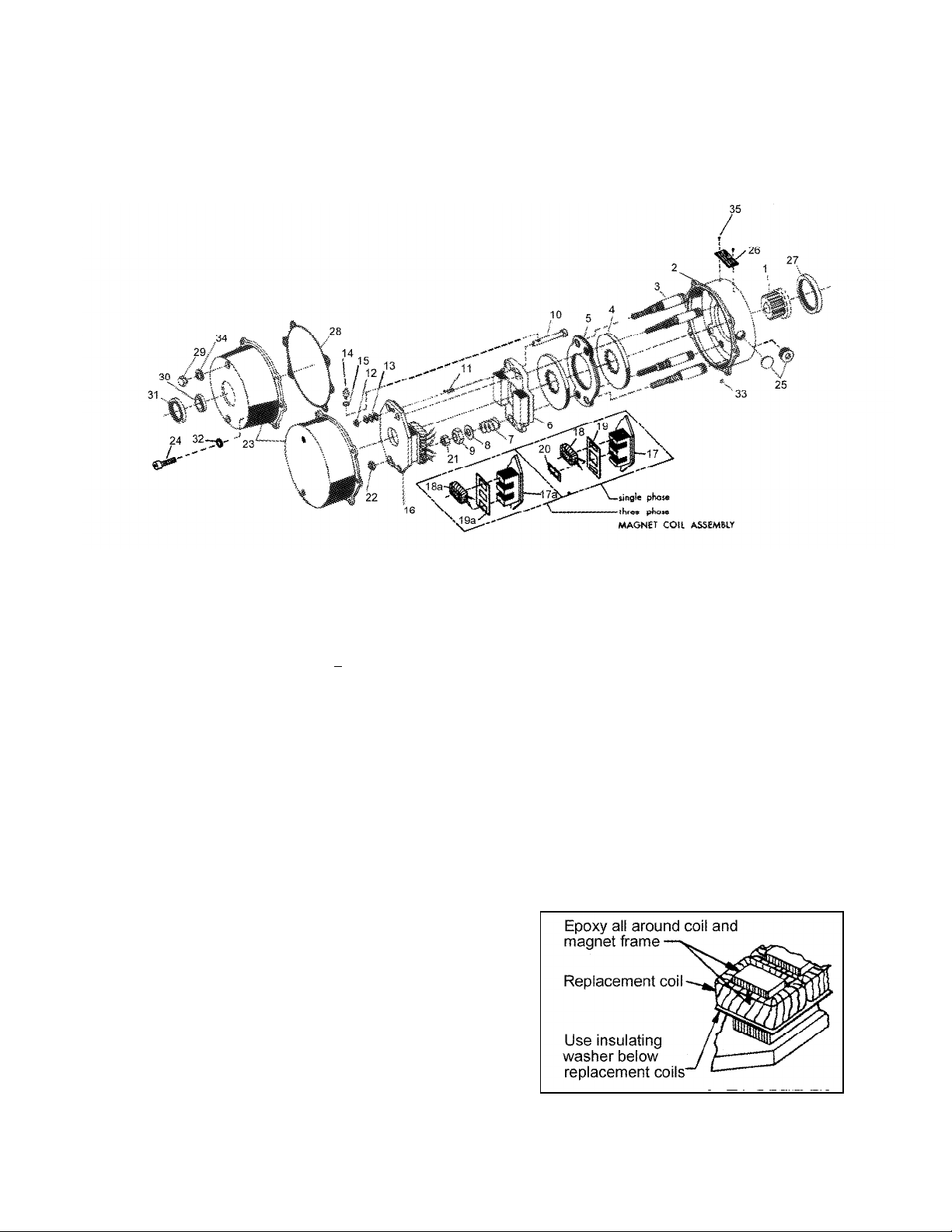
16 1Magnet Assembly, Single Phase –Complete with Coils K080126 (3)
16 1Magnet Assembly, Three Phase –Complete with Coils K080127 (3)
17 1Magnet Plate w/o Coils, Single Phase K080152-001
17a 1Magnet Plate w/o Coils, Three Phase K080101-001
18 4Magnet Coil –Single Phase K080083 (3)
18a 6Magnet Coil –Three Phase H080062 (3)
19 2Insulating Washer –Single Phase G080148-001
19a 2Insulating Washer –Three Phase G080016-001
20 2Shading Coil, Single Phase Only G080022-001
21 4Gap Adjusting Nut W003003-023
22 4Gap Adjusting Nut W003001-020
23 1Cover, Standard L080067-001 L080056-002
23 1Cover, w/ Thru Shaft L080067 (4) L080056-003
24 6Cover Screw W001013-028A
25 1Conduit Hole Plug W008003-001 W010002-004
26 1Name Plate H050020-001
27 1Hub Seal --- W011001-008 ---
28 1Cover Gasket --- K080143-001
29 2Release Cap --- G060170-002
30 1Thru-Shaft Sleeve --- H080036 (5)
31 1Thru-Shaft Seal --- W011001-007
32 6Lockwasher, 1/4 W004007-009 W004006-006 W004007-009
33 1Drain Hole Plug --- W010002-001
34 2Release Cap Gasket --- G070381-001
35 2Drive Screw W001012-048
(1) Number of rotating discs is shown as second digit of Model No. (3) Basic part number shown –specify model number, voltage,
Example: 2-82050-28 phase and frequency.
(2) Number of stationary discs is one less than the number of rotating discs. (4) Basic part number shown –specify shaft diameter.
(5) Basic part number shown –specify shaft diameter and keyway.