Dynamode 24 ports Giga managed switch User manual

Gigabit Management Switch
Quick Installation Guide
Features:
Comply with IEEE 802.3 Ethernet、IEEE 802.3z、802.3x、802.1q、802.1p、
802.1d and 802.3ab standards
Backbone width 48G
Store-forward structure
Support 80 IEEE 802.1 Q Tag VLAN、 24 Port VLAN
8K MAC address
Each port supports MAC address learning
Port Trunk
Port Mirror
Support 802.1x pass through
Broadcasting storm control
Port security including static MAC bonding and IP address filter
Port bandwidth control
Supoort WEB and RS232(out of band) management
Support DHCP protocol
Firmware upgrade through TFTP、HTTP、XMODEM,and setting file
upload and download through TFTP、HTTP
High quality internal power supply
1U steel 19” rack mountable case design
Dynamode Ltd

Specifications:
Model 24 ports Giga managed switch
Standards IEEE 802.3 Ethernet、802.3x、802.1Q、802.1p、IEEE802.1Dand 802.3ab
Ports 24 1000Base-T ports
Cable 10BASE-T:Cat 3 or above UTP and STP
100BASE-TX:Cat 5 UTP and STP
1000BASE-T:Cat 5 UTP and STP
MAC address 8K
Backbone width 48G
Transmission rate 10Mbps:14880pps;100Mbps:148800pps;1000Mbps:1488000pps
10/100M Link/Act
LED other Power
Size (L×W×H)
(mm) 440×285×44
Environment Working temperature:0℃~40℃;Humidity:10%~90%
Store temperature:-40℃~70℃; Humidity: 5%~90%
Power Input:180-260VAC,50-60Hz;
Step 1 Installation
The site where you place the switch may greatly affect its performance. When
installing, take the following into your consideration.
1.1 Installation method
Follow the guidelines below to install the switch.
Install the switch in a fairy cool and dry place. See the Technical Specification for the
acceptable temperature and humidity operation ranges.
Install the switch on a sturdy, level surface that can support its weight,(at least 4KG).
Connect the power cord to the switch and the power outlet. The distance is no more
than 150cm.
Leave at least 10cm(about 4 inches) of space at the front and rear of the switch for
ventilation.
1.2 Desktop or shelf Installation
When installing the switch on the desktop or shelf, please attach the rubber feet to the
switch. Peel off the protective paper on the pads and attach them on the bottom of the
switch(one at each corner).
1.3 Rack Installation
The switch is rack-mountable and can be installed on an EIA-19 inch equipment rack.
To do this, first install the mounting brackets on the switch’s side panels(one on each
side), secure them with the included screws, and then use the screws provided with
the equipment rack to mount the switch on the 19 inch rack.
Dynamode Ltd

1.4 Power on the switch
The switch has a universal power supply ranging from 100V to 220V AC, 50-60Hz
power source. The AC power connector is located at the rear of the unit adjacent to
and the system fan. The switch’s power supply will adjust to the local power source
automatically.
Step 2 Connecting the switch
This chapter describes how to connect the switch to you Fast Ethernet nework.
2.1 Installation method
A PC can be connected to the switch via a two-pair Category 3,4 or 5 UTP/STP
straight-through cable. For 100Mbps operation Category 5 or 5e UTP and for
1000Mbps operation Category 5e or 6 UTP must be used. The PC(equipped with a
RJ-45 10M Ethernet or 100M Fast Ethernet NIC) should be connected to any port of
the Switch. The LED indicators for PC connection are dependent on the LAN card
capabilities. If the LED indicators do not light after making a proper connection,
check the PC LAN card, the cable, the switch conditions and connections.
2.2 Hub to Switch
A Hub (10 or 100Base-T) can be connected to the switch via a two-pair Category 3,4
or 5 UTP/STP straight-through cable. For 100Mbps operation Category 5 must be
used. The connection is accomplished from any port of the Hub to any port of the
Switch.
2.3 Switch to Switch (other devices)
The switch can be connected to another switch or other devices (routers, bridges, etc.)
via a two-pair Category 3,4 or 5 UTP/STP straight or crossover cable. A Category 5
cable must be used for 100Mbps operation. The connection can be done from any
(MDI-X) port of the switch (Switch A) to any of the 10Mbps, 100Mbps (MDI-X) port
of the other switch (Switch B) or other devices.
2.4 Port Speed & Duplex Mode
After plugging the selected cable to a specific port, the system uses auto-negotiation
to determine the transmission mode for any new twisted-pair connection:
If the attached device does not support auto negotiation or has auto- negotiation
disabled, an auto sensing process is initiated to select the speed and set the duplex
mode to half-duplex.
Step 3 Manegement
This chapter describes three manamgement methods of the Switch.
·Web-based mangagement
·Console management
·Telnet management
Dynamode Ltd

3.1 Web-based management
The switch has a Web GUI interface for switch configuration. The Switch can be
configured through the Web browser. .A network administrator can manage, control,
and monitor the Switch from the local LAN. This section indicates how to configure
the Switch to enable its smart functions including:
System configuration: Overal configuaration, Ports configuration, Port VLAN,
802.1Q VLAN, 802.1Q VLAN advanced setting, Port trunking, MAC bonding, MAC
list management, Port mirror, QoS, Port filtering, Port width setting, Broadcasting
storm control
System status monitor: Port statical information
System maintenance: Restort to factory default settings, Firmware upgrade, system
file save and quit
Before you configure this device, note that when the Switch is configured through an
Ethernet connection, the manager PC must be set on the same the IP network. For
example,when the default network address of the default IP address of the Switch is
192.168.1.254,then the manager PC should be set at 192.168.2.x(where x is a number
between 1 and 256 except 254),and the default subnet mask is 255.255.255.0.
Open an Internet Explorer 5.0 or above Web browser.
Enter the IP address http://192.168.1.254 (the factory-default IP address setting)in the
address loaction.
NOTE:
The factory-default IP address: 192.168.1.254, Sub-network mask
255.255.255.0,Gateway 192.168.1.1
Through the Web Management Utility, you do need to remember the IP Address;
select the device shown in the Monitor List of the Web Management Utility to settle
the device on the browser.
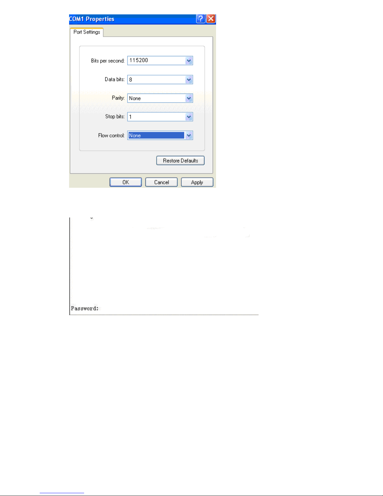
When the following dialog page appears, enter the default user name and passport and
press Login to enter the main configuration window.
NOTE:
The factory-default User name is empty. Pass word is “admin ”
Dynamode Ltd

After entering the password, you can access main page of your switch.
3.2 Console Management (Out-of-band)
A local console is a terminal or a workstation running a terminal emulation program
that is connected directly to the switch via the RS-232 console port on the rear of the
switch. Local console management uses the terminal connection to operate the
console program built-in to the Switch a network Administer can manage, control and
monitor the switch from the console program.
To start using the Console Management program, first connect an EIA-232 serial
cable to a COM port on a PC or notebook computer and to the Console Port on the
rear panel of the Switch.
If you are using Microsoft Windows, boot up the computer, go to
“Start”-“Programs”-“Accessories”,-“Communications”, and open the
“HyperTerminal”. After that follow the instructions below to setup a new terminal
connection software, please select the correct COM port and setup the connection
properties according to step 3 below.
1. Type in a name for the connection, select an icon for the connection, and click
“OK”.
2. Select the COM port that you are using for this connection and click “OK”.
3. Setup the COM port properties by using the information below and click“OK”.
NOTE:
The console port is set at the factory for the following configuration:
Baud rate: 115200 bps
Data width: 8 bits
Parity: none
Stop bits:1
Flow Control: None
Dynamode Ltd

4. You should see some boot-up messages displayed within your “HyperTerminal”
session.
5. At the “password” field type in“admin”and hit“Enter”.You are now logged into
the Switch’s configuration program.
Dynamode Ltd

NOTE:
The factory-default User name is empty.
Pass word is “admin”
Dynamode Ltd
Table of contents
Popular Switch manuals by other brands

Malmbergs
Malmbergs 99 170 35 instruction manual

Longshine
Longshine GS9120 manual

Digitus
Digitus Desktop 4-PortAudio-Combo-KVM Switch user manual

Interlogix
Interlogix NS3503-16P-4C Quick installation guide

Comnet
Comnet CNGE28FX4TX24MS Series Installation and operation manual

Panduit
Panduit ATLONA AT-UHD-CLSO-601 manual