Dynaset HKR 500 User manual

rev 1.1
HKR 500
HKR 800
HKR 1300
HKR 2000
HKR 2500
HKR 4000
HKR 5000
HKR 7500
Download PDF version from www.Dynaset.com/manuals Keycode: MQT36Y
HYDRAULIC SCREW COMPRESSORS
USER MANUAL


Dynaset Oy | Menotie 3, FI-33470 Ylöjärvi, Finland | tel: +358 3 3488 200 | inf[email protected] | www.dynaset.com
HYDRAULIC SCREW COMPRESSORS
TABLE OF CONTENTS
1. GENERAL 7
1.1. PRODUCT INFORMATION 7
1.2. PRODUCT IDENTIFICATION KEY 7
1.3. TYPE PLATE 8
1.4. HKR COMPRESSOR LINEUP 9
1.5. MAIN COMPONENTS OF HKR COMPRESSOR 10
2. SAFETY 11
2.1. SAFETY PRECAUTIONS 11
2.2. SAFETY EQUIPMENT 11
2.3. OPERATING SAFETY 12
2.4. MAINTENANCE SAFETY 13
2.5. WARNING LABELS 13
3. OPERATING PRINCIPLES 15
3.1. OPERATING DESCRIPTION 15
3.2. LUBRICATION SYSTEM OF COMPRESSOR 17
3.3. PRESSURE AND COMPRESSION RATIO 17
3.4. INTAKE VALVE 18
3.4.1. FUNCTIONAL PRINCIPLE OF PNEUMATIC INTAKE CONTROL 19
3.5. MULTIBLOCK 20
3.6. OIL NONRETURN VALVE 22
3.7. AIROIL SEPARATING ELEMENT 23
3.8. MINIMUM PRESSURE VALVE 24
3.9. OIL FILTER 25
3.10. OIL THERMOSTAT 26
4. INSTALLATION 27
4.1. BEFORE INSTALLATION 27
4.1.1. HYDRAULIC SYSTEM OF A BASE MACHINE 27
4.1.2. DYNASET VALVES 34
4.2. INSTALLING DYNASET HYDRAULIC PRODUCT 35
4.2.1. PLACING DYNASET HYDRAULIC PRODUCT 35
4.2.2. INSTALLING DYNASET VALVES 35
4.2.3. CONNECTING HYDRAULIC HOSES 35
4.2.4. HYDRAULIC FLUIDS 37
4.3. INSTALLING HKR COMPRESSOR 37
4.3.1. MAXIMUM INCLINATIONS 37
4.3.2. CONNECTION TO THE AIR SUPPLY SYSTEM 38

Dynaset Oy | Menotie 3, FI-33470 Ylöjärvi, Finland | tel: +358 3 3488 200 | inf[email protected] | www.dynaset.com
HYDRAULIC SCREW COMPRESSORS
TABLE OF CONTENTS
5. OPERATION 39
5.1. BEFORE STARTING THE COMPRESSOR 39
5.2. STARTING THE COMPRESSOR 40
5.3. AIR AND OIL TEMPERATURES 41
5.4. AIR HUMIDITY 42
5.5. OFFLOAD MODE 43
5.6. COLD STARTS 43
5.7. STOPPING THE COMPRESSOR 44
6. MAINTENANCE 45
6.1. MAINTENANCE INTERVALS 46
6.2. HYDRAULIC FLUIDS 46
6.3. COMPRESSOR OILS 47
6.3.1. MULTIGRADE OIL 48
6.3.2. TEMPERATURES AND OIL TYPES 48
6.4. CLEANING THE COMPRESSOR 49
6.5. OIL LEVEL CHECK 50
6.6. OIL CHANGE 52
6.7. REPLACING OIL FILTER 55
6.8. REPLACING AIROIL SEPARATING ELEMENTS 57
6.9. REPLACING AIR FILTER ELEMENT 59
6.10. ADJUST THE OFFLOAD PRESSURE 61
6.11. TROUBLESHOOTING 62
7. MANUFACTURER’S LIMITED WARRANTY 67
8. PRODUCT DISPOSAL 69
9. DECLARATION OF CONFORMITY 71
10. TECHNICAL SPECIFICATIONS 73

Dynaset Oy | Menotie 3, FI-33470 Ylöjärvi, Finland | tel: +358 3 3488 200 | inf[email protected] | www.dynaset.com
HYDRAULIC SCREW COMPRESSORS
TABLE OF PICTURES
Picture 1: Identication key for HKR 7
Picture 2: Type plate 8
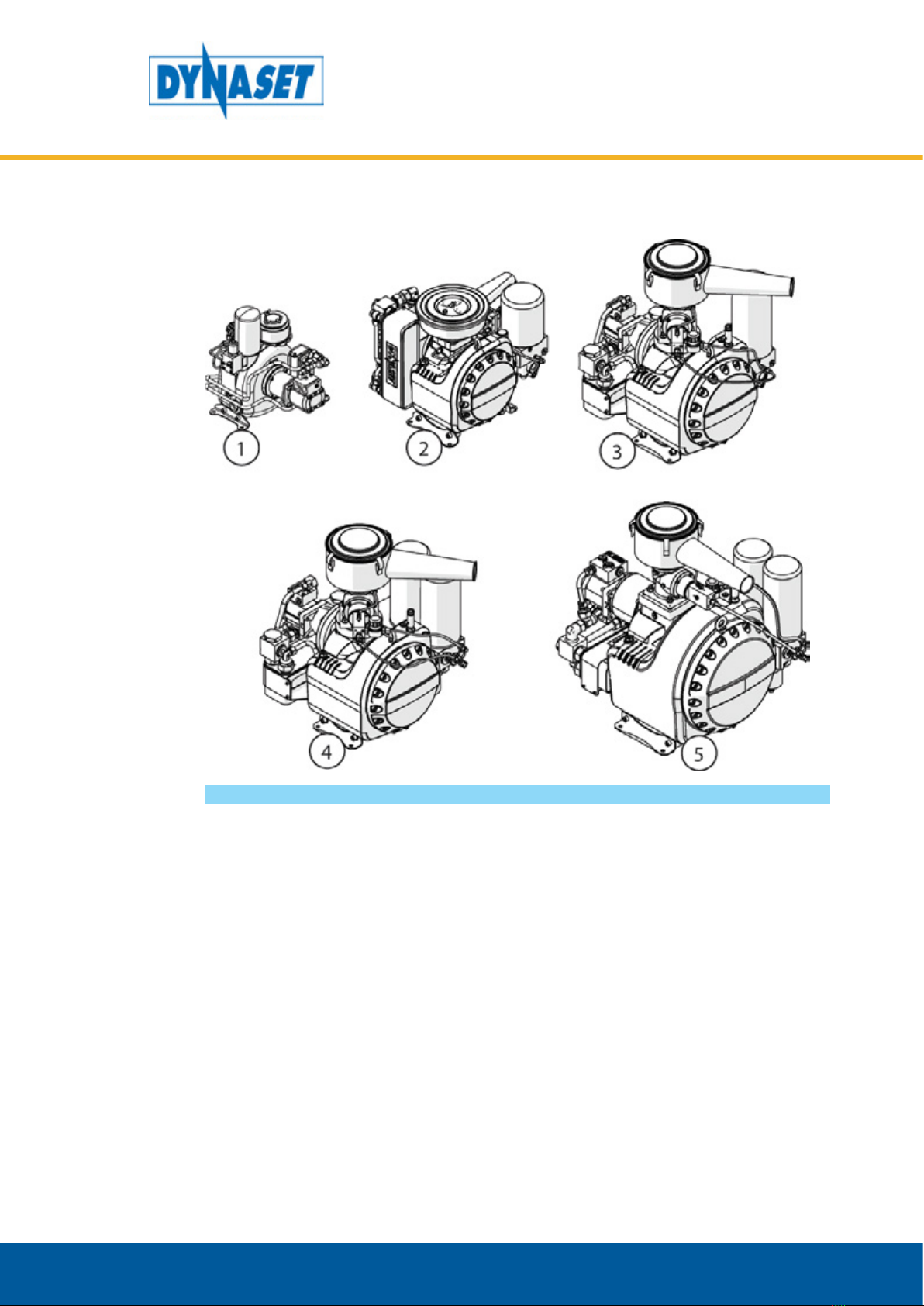
Picture 3: HKR compressor line-up 9
Picture 4: Main components of HKR compressor 10
Picture 5: Operating description: Air intake and lubrication 15
Picture 6: Operating description: Air output, oil ltering and cooling 16
Picture 7: The nominal discharge of hydraulic screw compressor 17
Picture 8: Operating principles of intake valve 18
Picture 9: Functional principle of pneumatic intake control 19
Picture 10: Multiblock of HKR 1300 - HKR 2500 20
Picture 11: Multiblock of HKR 4000 and HKR 5000 - HKR 7500 21
Picture 12: Operating principle of oil non-return valve 22
Picture 13: Operating principle of air-oil separating element 23
Picture 14: Operating principle of minimum pressure valve 24
Picture 15: Operating principle of oil lter 25
Picture 16: Operating principle of oil thermostat 26
Picture 17: Open centre hydraulic system with Load Sensing variable displacement pump 28
Picture 18: Connection gure for open centre hydraulic system with Load Sensing variable displacement pump 29
Picture 19: Closed centre hydraulic system with Load Sensing variable displacement pump 30
Picture 20: Connection gure for closed centre hydraulic system with Load Sensing variable displacement pump 31
Picture 21: Hydraulic system with xed displacement pump 32
Picture 22: Connection gure for hydraulic system with xed discplacement pump 33
Picture 23: Load sensing valve LSV 34
Picture 24: Priority valve PV-SAE 34
Picture 25: Placing the HKR compressor 35
Picture 26: Installing hydraulic hoses 36
Picture 27: P-line operational hydraulic ow 36
Picture 28: Base machine’s hydraulic pumps 36
Picture 29: Return line connection 37
Picture 30: Maximum inclination angle of HKR compressor 37
Picture 31: Air supply system connection 38
Picture 32: Air supply line hose diameter and length 38
Picture 33: Oil level of the HKR compressor 39
Picture 34: Starting the compressor 40
Picture 35: Compressed air must not be used as breathing air 41
Picture 36: Normal operating ambient temperature 41
Picture 37: Operating in extreme ambient temperatures 42
Picture 38: Operating air humidity 42
Picture 39: Oil return sight glass 43
Picture 40: Stopping the compressor 44
Picture 41: Depressurizing the compressor 45
Picture 42: Temperatures and oil types 48
Picture 43: Location of oil ller cap 50

Dynaset Oy | Menotie 3, FI-33470 Ylöjärvi, Finland | tel: +358 3 3488 200 | inf[email protected] | www.dynaset.com
HYDRAULIC SCREW COMPRESSORS
TABLE OF PICTURES

Dynaset Oy | Menotie 3, FI-33470 Ylöjärvi, Finland | tel: +358 3 3488 200 | inf[email protected] | www.dynaset.com 7
HYDRAULIC SCREW COMPRESSORS
GENERAL
1. GENERAL
This manual contains general information about assembly, installation, operation
and maintenance of the DYNASET HKR hydraulic screw compressors.
ATTENTION!
Read this user manual before installation, use or maintenance of the HKR
compressor to ensure proper handling, operation and maintenance right
from the beginning. Pay attention to warnings and safety instructions.
READ CHAPTER “2. SAFETY” for more information.
1.1. PRODUCT INFORMATION
HKR compressors are compact and integrated all-in-one units, especially designed
for mobile installation.The only power source needed is a hydraulic system of base
machine which provides compressor the required hydraulic flow and pressure.
HKR compressor converts the hydraulic power into high quality compressed air
and it can be installed in almost any working machine. HKR compressors are used
to power for example pneumatic tools, filling tires, air flushing, purge air protection
equipments, cleaning equipments and CAFS foam generation.
DYNASET HKR compressors are designed to meet regular modern compressed air
demands.
1.2. PRODUCT IDENTIFICATION KEY
The product identification key describes the characteristics of the DYNASET
product. The product identification key is on the product type plate which is
attached onto every DYNASET product.
29-10/500HKR
1 2 3 4
Picture 1: Identification key for HKR
1.Product Group HKR Hydraulic Screw Compressor
2.Maximum Discharge. It is the maximum amount of air flow (l/min) that HKR hy-
draulic screw compressor can produce at discharge pressure of 6 bar (according
to ISO1217(1996).)
3.Maximum Discharge Pressure. It is the maximum air pressure (bar) that HKR hy-
draulic screw compressor can produce.
4.Maximum hydraulic flow. It is the maximum hydraulic flow that HKR hydraulic
screw compressor is designed to run. Do not exceed the maximum hydraulic
flow.

Dynaset Oy | Menotie 3, FI-33470 Ylöjärvi, Finland | tel: +358 3 3488 200 | inf[email protected] | www.dynaset.com
8
HYDRAULIC SCREW COMPRESSORS
GENERAL
1.3. TYPE PLATE
Picture 2: Type plate
The products type plate shows the following information.
1. Product identification key
2. Product code
3. Serial number
4. Maximum hydraulic flow
5. Maximum hydraulic pressure
6. Production month / year
7. Output air flow rate
and pressure.
8. Manufacturer’s contact
information

Dynaset Oy | Menotie 3, FI-33470 Ylöjärvi, Finland | tel: +358 3 3488 200 | inf[email protected] | www.dynaset.com 9
HYDRAULIC SCREW COMPRESSORS
GENERAL
1.4. HKR COMPRESSOR LINEUP
Picture 3: HKR compressor line-up
1. HKR 500 - HKR 800
2. HKR 1300 - HKR2000-
HKR 2500
3. HKR 4000
4. HKR 5000
5. HKR 7500

Dynaset Oy | Menotie 3, FI-33470 Ylöjärvi, Finland | tel: +358 3 3488 200 | inf[email protected] | www.dynaset.com
10
HYDRAULIC SCREW COMPRESSORS
GENERAL
1.5. MAIN COMPONENTS OF HKR COMPRESSOR
Picture 4: Main components of HKR compressor
1. Safety valve
2. Intake valve
3. Hydraulic motor
4. Temperature probe connection
5. Lifting eyes
6. DYNASET type plate
7. Intake filter
8. Air pressure control valve
9. Oil thermostat
10. Oil filler cap
11. Heat exchanger
12. Heat exchanger by-
pass check valve
13. Oil filter
14. Oil return line sight glass
15. Minimum pressure valve
16. Compressed air outlet (AP)
17. Oil drain plug
18. Compressor block
19. Hydraulic pressure line (P)
20. Hydraulic return line (T)
21. Air-oil separator element

11
Dynaset Oy | Menotie 3, FI-33470 Ylöjärvi, Finland | tel: +358 3 3488 200 | inf[email protected] | www.dynaset.com
HYDRAULIC SCREW COMPRESSORS
SAFETY
2. SAFETY
2.1. SAFETY PRECAUTIONS
ATTENTION!
Operators and maintenance personnel must always comply with local
safety regulations and precautions in order to close out the possibility of
damages and accidents.
The pressure in both hydraulic and compressed air circuits is considerably high.
Keep the condition of your equipment and hydraulic system under constant
observation.
WARNING
HIGH PRESSURE AIR AND OIL!
Can cause severe injuries.
Always wear appropriate clothing
and safety equipment.
Couplings, valves and hoses need to be kept tight and clean to avoid possible
leakages. Leaks in the hydraulic system must be repaired immediately to avoid
injuries caused by high pressure bowouts.
In order to avoid possible accidents, it is not allowed to clean or inspect HKR
compressor or pneumatic tools when hydraulic or/and pneumatic circuit is
pressurized. Prior to any cleaning, inspection and service, hydraulic system of your
base machine must be stopped and both hydraulic and pneumatic circuits must
be depressurized.
2.2. SAFETY EQUIPMENT
Always wear appropriate clothing and safety equipment such as safety goggles,
safety shoes and ear protection when operating the compressor.

12 Dynaset Oy | Menotie 3, FI-33470 Ylöjärvi, Finland | tel: +358 3 3488 200 | inf[email protected] | www.dynaset.com
HYDRAULIC SCREW COMPRESSORS
SAFETY
2.3. OPERATING SAFETY
When operating the compressor, beware of unit parts warmed by hot hydraulic
oil.
WARNING
RISK OF BURNS!
Parts of the unit, oil, and oil filler cap
can be hotter than 80 °C!
Wear personal safety equipment!
Never aim compressed air at a person.
WARNING
HIGH PRESSURE AIR!
Never aim compressed air at a person.
Can cause severe injuries.
ATTENTION!
Do not exceed the maximum pressure, temperature and load.

13
Dynaset Oy | Menotie 3, FI-33470 Ylöjärvi, Finland | tel: +358 3 3488 200 | inf[email protected] | www.dynaset.com
HYDRAULIC SCREW COMPRESSORS
SAFETY
2.4. MAINTENANCE SAFETY
ATTENTION
Installation and service of both hydraulic and pneumatic equipment must
be performed by qualified and experienced personnel only.
NOTE!
When carrying out any maintenance to HKR compressor, keep the
components of the system clean. This is important to ensure safe, reliable
and longlife operation of your equipment.
Hydraulic system of a base machine should be maintained according to the service
program.
2.5. WARNING LABELS
Warning labels are included with each main product.
Product recipient is obligated to place warning labels on the DYNASET product.
Attach labels to visible and appropriate place onto or close to DYNASET product
where it’s easily seen. Clean surface with solvent detergent before attaching labels.
USE EAR PROTECTION
AND SAFETY GLOGGLES!
READ USER
MANUAL!
HIGH PRESSURE
AIR!
HOT SURFACE!
HIGH PRESSURE
OIL!

14 Dynaset Oy | Menotie 3, FI-33470 Ylöjärvi, Finland | tel: +358 3 3488 200 | inf[email protected] | www.dynaset.com
HYDRAULIC SCREW COMPRESSORS
SAFETY

15
Dynaset Oy | Menotie 3, FI-33470 Ylöjärvi, Finland | tel: +358 3 3488 200 | inf[email protected] | www.dynaset.com
HYDRAULIC SCREW COMPRESSORS
OPERATING PRINCIPLES
3. OPERATING PRINCIPLES
3.1. OPERATING DESCRIPTION
Picture 5: Operating description: Air intake and lubrication
1. The screws of screw compressor are driven by hydraulic motor. The rotation of
screws creates suction and air starts to flow.
2. The air flows through intake filter and valve into the compression chamber.
3. Intake air is compressed between male and female screws. Oil is mixed with air
and injected into screws for lubrication and cooling.
4. The majority of the oil is separated from the oil-air-mixiture in a separating tank
in compressor block.

16 Dynaset Oy | Menotie 3, FI-33470 Ylöjärvi, Finland | tel: +358 3 3488 200 | inf[email protected] | www.dynaset.com
HYDRAULIC SCREW COMPRESSORS
OPERATING PRINCIPLES
Picture 6: Operating description: Air output, oil filtering and cooling
5. The air-oil mixiture flows to the air-oil separating element where the oil is
filtered out down to a residual content of < 3 mg/m3.
6. Compressed and filtered air continues from air-oil separating element to the air
supply system through minimum pressure valve and AP-port.
7. Depending on the oil temperature, the oil thermostat valve routes the oil
flow through the oil cooler or directly to the oil filter. Optimum operating
temperature of oil is adjusted by integrated thermostat valve.
8. The oil flows from the oil filter to various injection points in the compressor
block.
When air supply line is closed and preset air pressure is reached, compressor starts
to run automatically in off-load mode. Pneumatically controlled intake valve is
closed and compressor’s internal pressure drops to 5.5 bar. Pressure in supply line
remains until supply line is opened.
When the compressed air in air supply line is needed, off-load automatic controls
the intake valve according to the current air demand.

17
Dynaset Oy | Menotie 3, FI-33470 Ylöjärvi, Finland | tel: +358 3 3488 200 | inf[email protected] | www.dynaset.com
HYDRAULIC SCREW COMPRESSORS
OPERATING PRINCIPLES
The nominal discharge is achieved when the compressor is rotated by hydraulic
flow adequate to the nominal rotation speed.
HYDRAULIC FLOW (l/min)
0
DISCHARGE (l/min)
Qpi_nom
Qpi_min
Qhy_min Qhy_nom
Picture 7: The nominal discharge of hydraulic screw compressor
3.2. LUBRICATION SYSTEM OF COMPRESSOR
Compressor oil has following functions:
1. LUBRICATION: Pressure differential makes the oil spread along grooves to the
surfaces to be lubricated. Separate oil pump is not needed.
2. HERMETIZATION: Injected oil seals screw surfaces against each other.
3. COOLING: DYNASET HKR screw compressor is equipped with oil heat exchager.
The compressor’s heat is transferred to hydraulic system with heat exchanger.
HKR screw compressor requires cooling capacity from base machines hydraulic
system.
3.3. PRESSURE AND COMPRESSION RATIO
The rated absolute intake pressure is 1 bar (1000 hPa).
NOTE!
The reference barometric pressure at sea level is 1,0135 bar, when at 1000
m above sea level it drops to 0,9 bar.
When the operational pressure of HKR-compressor is 10 bar, compression ratio is
equal to:
The compression ratio for unit of (x) bar is calculated in the same way.

18 Dynaset Oy | Menotie 3, FI-33470 Ylöjärvi, Finland | tel: +358 3 3488 200 | inf[email protected] | www.dynaset.com
HYDRAULIC SCREW COMPRESSORS
OPERATING PRINCIPLES
3.4. INTAKE VALVE
The Dynaset HKR is equipped with an integrated intake valve that is mounted
directly on the compressor housing. It is triggered via air pressure control valve.
11
2
Intake valve open Intake valve closed
3
4
Picture 8: Operating principles of intake valve
1. Air inlet
2. Air outlet
3. Control piston
4. Sping

19
Dynaset Oy | Menotie 3, FI-33470 Ylöjärvi, Finland | tel: +358 3 3488 200 | inf[email protected] | www.dynaset.com
HYDRAULIC SCREW COMPRESSORS
OPERATING PRINCIPLES
3.4.1. FUNCTIONAL PRINCIPLE OF PNEUMATIC INTAKE CONTROL
1
23
Picture 9: Functional principle of pneumatic intake control
1. Intake valve
2. Air pressure control valve
3. 3/2 way valve
The intake valve is normally open. When the preset pressure at the air pressure
control valve is reached, the pilot air (blue in the picture) closes the intake valve.
When the intake valve is closed compressor is in standby mode.
When the air in air supply line is used and the pressure drops, the air pressure
control valve reduces the pilot air flow so that the intake valve opens and intake
regulator maintains the set pressure.
When the compressor unit is stopped, the rising pressure (red in the picture) above
the screws activates the 3/2 way valve. The pressure in the compressor is releaved
via the 3/2 way valve and the relief nozzle.

20 Dynaset Oy | Menotie 3, FI-33470 Ylöjärvi, Finland | tel: +358 3 3488 200 | inf[email protected] | www.dynaset.com
HYDRAULIC SCREW COMPRESSORS
OPERATING PRINCIPLES
3.5. MULTIBLOCK
The DYNASET HKR screw compressors (HKR 1300-7500) are equipped with a
multiblock into which the oil thermostat, the oil filter, the air-oil separating
elements, the minimum pressure valve, the non-return valve with the oil return
line, and the oil return line check are integrated.
1
5
4 6 3
2
987
HKR 1300 - 2500
Picture 10: Multiblock of HKR 1300 - HKR 2500
1. Air-oil separating element
2. Oil circulation connection Inlet
3. Oil circulation con-
nection Outlet
4. Oil return line check /
sight glass and nozzle
5. Housing
6. Oil thermostat
7. Oil separation return line
(integrated non return valve)
8. Minimum pressure valve
9. Oil filter
This manual suits for next models
7
Table of contents