Dynaset PPL 200 User manual

PPL 200
PPL 220
PPL 180
PPL 460
rev 1.2
06/18
HIGH PRESSURE PIPE CLEANING UNITS
USER MANUAL
Download PDF version from www.Dynaset.com/manuals Keycode: GLKCWR


Dynaset Oy | Menotie 3, FI-33470 Ylöjärvi, Finland | tel: +358 3 3488 200 | inf[email protected] | www.dynaset.com 3
Congratulations!
You have just purchased DYNASET hydraulic equipment!
The equipment allows you to maximize the productivity and
efficiency of your mobile machine. Read this User Manual
before using your new equipment. It contains important
information that will help you to take the full advance of the
technical features avaible in your equipment.
Please contact us for any feedback you might have on our
products. Your feedback is important to us for improving our
products and customer service.
We are constantly developing and releasing new innovations.
Please visit on our website and social media channels for the
latest news and updates.
www.dynaset.com
info@dynaset.com
www.facebook.com/dynaset
www.youtube.com/dynasetoy
www.twitter.com/Dynaset_ofcl
www.instagram.com/dynaset_official
Subscribe to our newsletter. Follow the QR
code!

HIGH PRESSURE PIPE CLEANING UNITS
TABLE OF CONTENTS
1. GENERAL 7
1.1. PRODUCT INFORMATION 7
1.2. PRODUCT IDENTIFICATION KEY 8
1.3. TYPE PLATE 9
1.4. PPL UNIT LINE-UP 10
1.5. MAIN COMPONENTS OF PPL UNIT 11
2. SAFETY 13
2.1. SAFETY PRECAUTIONS 13
2.2. SAFETY EQUIPMENT 13
2.3. OPERATING SAFETY 14
2.4. MAINTENANCE SAFETY 14
2.5. WARNING LABELS 15
3. OPERATING PRINCIPLES 17
3.1. OPERATING DESCRIPTION 17
4. INSTALLATION OF THE PPL UNIT 19
4.1. INSTALLATION TO A HYDRAULIC LINE 19
4.2. INSTALLATION WITH LS-CONNECTION 22
4.3. HYDRAULIC FLUIDS 22
4.4. INSTALLATION TO A WATER LINE 23
4.5. INSTALLATION OF ELECTRIC CONTROL CONNECTIONS 24
5. OPERATION 25
5.1. BEFORE OPERATING THE PPL UNIT 25
5.2. STARTING AND STOPPING THE PPL UNIT 25
5.3. HOSE REEL CONTROL 26
5.4. PIPE CLEANING 26
5.5. WORKING IN COLD TEMPERATURES 28

HIGH PRESSURE PIPE CLEANING UNITS
TABLE OF CONTENTS
6. MAINTENANCE 29
6.1. MAINTENANCE INTERVAL 29
6.2. HYDRAULIC FLUIDS 29
6.3. CLEAN THE PPL UNIT 30
6.4. CLEAN WATER FILTER 30
6.5. GREASE HOSE REEL 31
6.6. TROUBLESHOOTING 31
7. MANUFACTURER’S LIMITED WARRANTY 33
8. PRODUCT DISPOSAL 35
9. DECLARATION OF CONFORMITY 37
10. TECHNICAL SPECIFICATIONS 39

Dynaset Oy | Menotie 3, 33470 Ylöjärvi | puh. 03 3488 200 | info@dynaset.com | www.dynaset.com
HIGH PRESSURE PIPE CLEANING UNITS
TABLE OF PICTURES
Picture 1: Identication key for PPL units 8
Picture 2: Type plate 9
Picture 3: PPL unit 10
Picture 4: Main components of PPL unit 11
Picture 5: Operating description of PPL unit 17
Picture 6: Operating description of HPW pump 1 18
Picture 7: Operating description of HPW pump 2 18
Picture 8: Hydraulic connections of PPL unit 19
Picture 9: Example of existing tool line installation 20
Picture 10: Example installation into a service van 21
Picture 11: Installation into water intake line 23
Picture 12: Electric control connector 24
Picture 13: Check water lter 25
Picture 14: Starting the PPL unit 25
Picture 15: Hose reel controls 26
Picture 16: Location of leakage detectors in HPW 29
Picture 17: Clean water lter 30
Picture 18: Grease hose reel 31

7
Dynaset Oy | Menotie 3, FI-33470 Ylöjärvi, Finland | tel: +358 3 3488 200 | inf[email protected] | www.dynaset.com
HIGH PRESSURE PIPE CLEANING UNITS
GENERAL
1. GENERAL
This manual contains general information about assembly, installation, operation
and maintenance of DYNASET PPL High Pressure Pipe Cleaning Unit.
ATTENTION!
Read this user manual before installation, use or maintenance of the PPL
unit to ensure proper handling, operation and maintenance right from
the beginning. Pay attention to warnings and safety instructions. READ
CHAPTER ”2. SAFETY” for more information.
1.1. PRODUCT INFORMATION
The high pressure pipe cleaning unit is typically used in works such as unclogging
or defrosting pipes and sewers with high pressure water jets and manual high
pressure cleaning with spray gun.
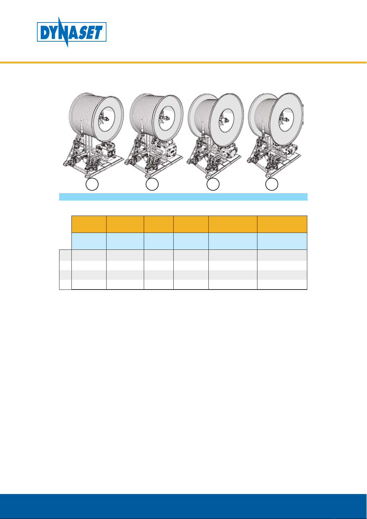
The Dynaset Hydraulic Hose Reel is designed for convenient at-work storage and
quick and safe handling of high pressure hose. Together with Dynaset HPW High
Pressure Water Pump, hose reel integrates core elements of professional pipe
cleaning equipment.
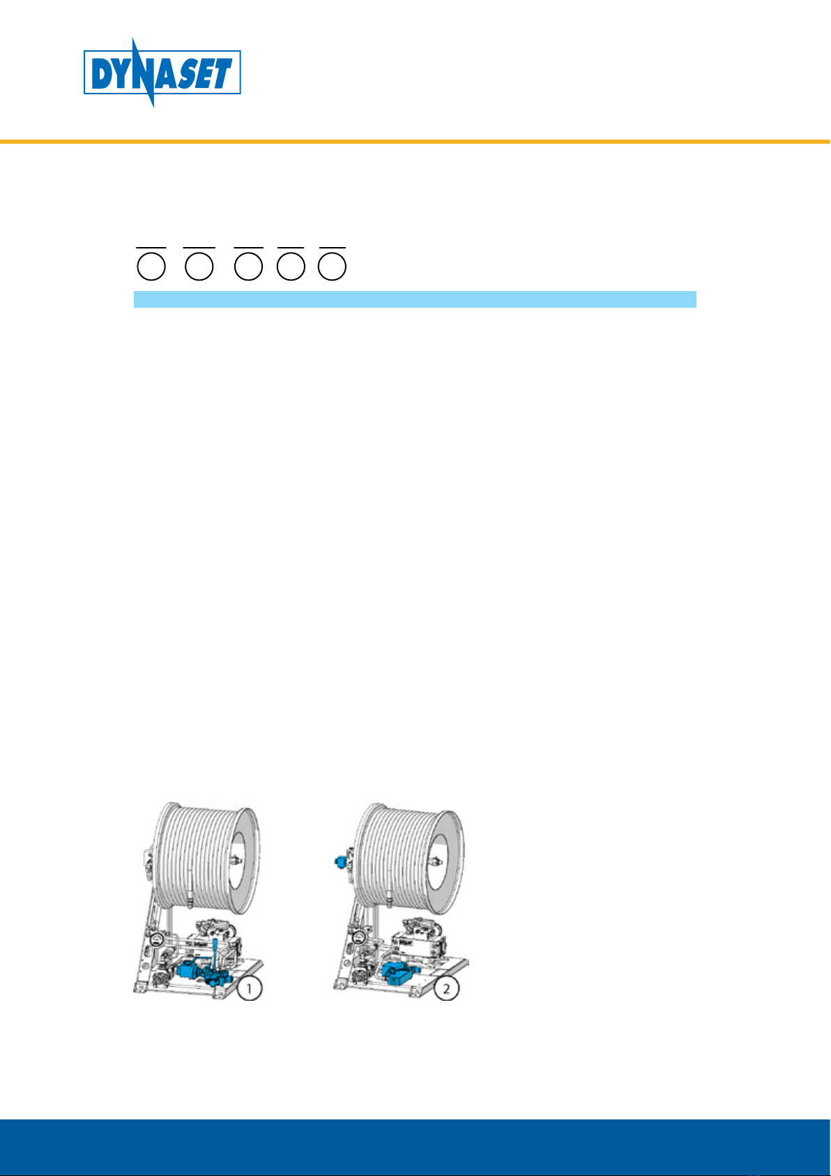
Unreeling the hose is easy due to the free reel rotation. The reel can be locked
hydraulically in any position. The hose reel is controlled with manual or solenoid
valve with positions for locking, reeling, and free rotation.
The rotation speed of the hose reel can be changed by adjusting the hydraulic
flow that rotates the reel motor. Reeling force is preset to 800 N, which equals to
50 bar pressure. The setting can be changed with a pressure limiter valve.
Dynaset also offers a wide range of different nozzles for pipe washing and
defrosting, and other purposes as well.

8Dynaset Oy | Menotie 3, FI-33470 Ylöjärvi, Finland | tel: +358 3 3488 200 | inf[email protected] | www.dynaset.com
HIGH PRESSURE PIPE CLEANING UNITS
GENERAL
1.2. PRODUCT IDENTIFICATION KEY
1 2 3 4 5
PPL - 200 - E12 - LS - W
Picture 1: Identification key for PPL units
1. Product group PPL High Pressure Pipe Cleaning Units.
2. WATER PUMP (Listed below)
HPW 200
Maximum pressure: 200 bar
Maximum flow: 30 l/min
Hydraulic pressure required: 210 bar
Hydraulic flow required: 45 l/min
HPW 220
Maximum pressure: 220 bar
Maximum flow: 50 l/min
Hydraulic pressure required: 210 bar
Hydraulic flow required: 70 l/min
HPW 180
Maximum pressure: 180 bar
Maximum flow: 90 l/min
Hydraulic pressure required: 210 bar
Hydraulic flow required: 115 l/min
HPW 460
Maximum pressure: 460 bar
Maximum flow: 50 l/min
Hydraulic pressure required: 250 bar
Hydraulic flow required: 115 l/min
3. CONTROL TYPE (Listed below)
M = Manual pump and hose reel control. (1)
E12/E24 = Electric pump and hose reel control 12V/24V. (2)
4. Hydraulic flow is controlled with base machines Load-Sensing(LS) hydraulic pump.

9
Dynaset Oy | Menotie 3, FI-33470 Ylöjärvi, Finland | tel: +358 3 3488 200 | inf[email protected] | www.dynaset.com
HIGH PRESSURE PIPE CLEANING UNITS
GENERAL
5. PPL includes spray gun and addition hose reel for spray gun (W).
1.3. TYPE PLATE
PPL 220 - E24 - LS - W
70 l/min
12345-678Dxxxxxxxxx
210 bar 09/16
Qw = 50 l/min Pw = 220 bar
Type
Nr
Oil Flow
Manufacturer:
Dynaset Oy
33470 Ylöjärvi Finland
www.dynaset.com
Tel +358 3 3488200
YearPressure
Code
Made in Finland
POWERED BY HYDRAULICS
1
23
4
7
8
5
6
Picture 2: Type plate
The products type plate shows the following information.
1. Product identification key
2. Product code
3. Serial number
4. Maximum hydraulic flow
5. Maximum hydraulic pressure
6. Production month / year
7. Output water flow
rate and pressure.
8. Manufacturer’s contact
information

10 Dynaset Oy | Menotie 3, FI-33470 Ylöjärvi, Finland | tel: +358 3 3488 200 | inf[email protected] | www.dynaset.com
HIGH PRESSURE PIPE CLEANING UNITS
GENERAL
1.4. PPL UNIT LINE-UP
1 2 3 4
Picture 3: PPL unit
MODEL PUMP WATER
FLOW
WATER
PRESSURE HOSE REEL DEFAULT HOSE
l/min bar Diameter (mm),
width (mm) Diameter, length
1 PPL 200 HPW 200 30 200 500 - 300 3/8”, 50m
2 PPL 220 HPW 220 50 220 500 - 300 1/2”, 50m
3 PPL 180 HPW 180 90 180 600 - 300 3/4”, 50m
4 PPL 460 HPW 460 50 460 600 - 300 1/2”, 100m
All PPL units has option for:
• Manual or electric control (12V/24V)
• Connection for Load-Sensing pump
• Spray gun with hose reel
• Mounting stand kit for installation

11
Dynaset Oy | Menotie 3, FI-33470 Ylöjärvi, Finland | tel: +358 3 3488 200 | inf[email protected] | www.dynaset.com
HIGH PRESSURE PIPE CLEANING UNITS
GENERAL
1.5. MAIN COMPONENTS OF PPL UNIT
1311
4
5 9 6 10
2 7 12
3 1 8
Picture 4: Main components of PPL unit
1. Frame
2. Hose reel
3. HPW pump
4. Reel motor
5. Hydraulic oil in (P)
6. Hydraulic oli return (T)
7. Hose
8. Water in (S)
9. HPW on/off valve (manual)
10. Reel winding lever (manual)
11. Pressure gauge
12. Reel winding speed
adjustment
13. Spray gun (optional)
14. Hose reef for spray
gun (optional)

12 Dynaset Oy | Menotie 3, FI-33470 Ylöjärvi, Finland | tel: +358 3 3488 200 | inf[email protected] | www.dynaset.com
HIGH PRESSURE PIPE CLEANING UNITS
GENERAL

Dynaset Oy | Menotie 3, FI-33470 Ylöjärvi, Finland | tel: +358 3 3488 200 | inf[email protected] | www.dynaset.com 13
HIGH PRESSURE PIPE CLEANING UNITS
SAFETY
2. SAFETY
2.1. SAFETY PRECAUTIONS
ATTENTION!
Operators and maintenance personnel must always comply with local
safety regulations and precautions in order to close out the possibility of
damages and accidents.
The pressure in both hydraulic oil and water circuits of PPL unit is considerably
high. Keep the condition of your equipment and hydraulic system under constant
observation.
WARNING
HIGH PRESSURE WATER AND OIL!
Can cause severe injuries.
Always wear appropriate clothing
and safety equipment.
Couplings, valves and hoses need to be kept tight and clean to avoid possible
leakages. Leaks in the hydraulic system must be repaired immediately to avoid
injuries caused by high pressure blowouts.
In order to avoid accidents, it is not allowed to clean or inspect PPL unit when
hydraulic fluid circuit is pressurized. Prior to any cleaning, inspection and service,
hydraulic system of your base machine must be stopped and all hydraulic fluid
circuits must be depressurized.
Prevent nozzles, water circuit and pipeline from freezing. Draining and air flushing
of the water circuit have to performed before ambient temperature reaches 0°C
or lower.
2.2. SAFETY EQUIPMENT
When operating close to the PPL unit, wear appropriate clothing and safety
equipment such as safety goggles, safety shoes and ear protection.

Dynaset Oy | Menotie 3, FI-33470 Ylöjärvi, Finland | tel: +358 3 3488 200 | inf[email protected] | www.dynaset.com
14
HIGH PRESSURE PIPE CLEANING UNITS
SAFETY
2.3. OPERATING SAFETY
When operating the PPL unit, beware of the unit parts warmed by hot hydraulic oil.
VAROITUS
PALOVAMMOJEN VAARA!
Laitteen osien ja öljyn lämpötila voi
ylittää 80 °C!
Käytä henkilökohtaisia suojavarusteita!
Never aim high pressure water at a person.
VAROITUS
KORKEAPAINEINEN VESI!
Älä koskaan suuntaa korkeapaineista
vesisuihkua ihmistä kohti.
Se voi aiheuttaa vakavia vammoja.
ATTENTION!
Do not exceed the maximum pressure, temperature or load.
2.4. MAINTENANCE SAFETY
ATTENTION
Installation and service of hydraulic equipment must be performed by
qualified and experienced personnel only.

Dynaset Oy | Menotie 3, FI-33470 Ylöjärvi, Finland | tel: +358 3 3488 200 | inf[email protected] | www.dynaset.com 15
HIGH PRESSURE PIPE CLEANING UNITS
SAFETY
NOTE!
When carrying out any maintenance to PPL unit keep the components of
the system clean. This is to ensure safe, reliable and longlife operation of
your equipment.
Hydraulic system of the base machine should be maintained according to the
service program.
2.5. WARNING LABELS
Product recipient is obligated to place warning labels on the DYNASET product.
Attach labels to visible and appropriate place onto or close to DYNASET product
where it’s easily seen. Clean surface with solvent detergent before attaching labels.
VARO
KUUMAA PINTAA.
KÄYTÄ
KUULONSUOJAIMIA
JA SUOJALASEJA.
LUE
KÄYTTÖOHJEET.
VARO
KORKEAPAINEISIA
ROISKEITA.
ESTÄ
JÄÄTYMINEN.

Dynaset Oy | Menotie 3, FI-33470 Ylöjärvi, Finland | tel: +358 3 3488 200 | inf[email protected] | www.dynaset.com
16
HIGH PRESSURE PIPE CLEANING UNITS
SAFETY

Dynaset Oy | Menotie 3, FI-33470 Ylöjärvi, Finland | tel: +358 3 3488 200 | inf[email protected] | www.dynaset.com 17
HIGH PRESSURE PIPE CLEANING UNITS
OPERATING PRINCIPLES
3. OPERATING PRINCIPLES
3.1. OPERATING DESCRIPTION
1
2
3
4
6
5
8
7
Picture 5: Operating description of PPL unit
The HPW pump (2) of the PPL unit is driven by hydraulic oil flow (1) from the base
machine. The HPW pump self-primes water from a water tank (3) and water is
filtered with a water filter (4). High pressure water is sprayed out through pipe
cleaning nozzle (5). Hose reel (6) is equipped with hydraulic motor (8) and it is
controlled with reel winding knob (7).
The nozzle head penetrates into pipeline due to recoil force of water jets coming
out from nozzles rear rim. Water jets pushes the nozzle forward and simultaneously
pushes the dirt out from the pipe. The water jet in forward direction opens the
channel for nozzle head and water hose.

Dynaset Oy | Menotie 3, FI-33470 Ylöjärvi, Finland | tel: +358 3 3488 200 | inf[email protected] | www.dynaset.com
18
HIGH PRESSURE PIPE CLEANING UNITS
OPERATING PRINCIPLES
The patented HPW-pump utilizes the reciprocal motion of the hydraulic piston.
Picture 6: Operating description of HPW pump 1
HPW-pump is driven by hyraulic flow through the hydraulic ports (P) and (T).
Hydraulic flow moves the piston assembly (1) into its extreme position. After
exteme position reached, reversal valve (2) inside the piston assembly changes
the direction of hydraulic flow and the piston assembly starts to move into the
opposite direction.
Picture 7: Operating description of HPW pump 2
Move of the piston assembly creates pressure and suction. Pump self-primes from
water supply line (S) and generates pressure into pressure line (WP). When piston
assembly moves away from head it creates underpressure (3) and water (or other
pumping fluid) is sucked through intake valve (4) into head.
When water piston moves towards the head, it creates pressure (5) and water is
pushed through pressure valve (6) into pumping fluid outlet (WP).

Dynaset Oy | Menotie 3, FI-33470 Ylöjärvi, Finland | tel: +358 3 3488 200 | inf[email protected] | www.dynaset.com 19
HIGH PRESSURE PIPE CLEANING UNITS
INSTALLATION
4. INSTALLATION OF THE PPL UNIT
4.1. INSTALLATION TO A HYDRAULIC LINE
The PPL unit is recommended to be installed into the base machine’s existing
hydraulic tool line or hydraulic power take off line depending on base machine.
Usually other installations are not required and the PPL unit can be operated from
the existing controls.
Install the hydraulic lines pressure (P) and return (T) ports to their corresponding
ports in the PPL unit.
PT
Picture 8: Hydraulic connections of PPL unit
Ensure that the hydraulic flow of the base machine is sufficient to run the unit. At
least the nominal hydraulic flow must be available to get the maximum washing
power. Lower hydraulic flow reduces washing power.
ATTENTION!
Ensure that the filtering degree and cooling capacity of the hydraulic
system are sufficient. READ CHAPTER ”10. TECHNICAL SPECIFICATIONS” for
more information.

Dynaset Oy | Menotie 3, FI-33470 Ylöjärvi, Finland | tel: +358 3 3488 200 | inf[email protected] | www.dynaset.com
20
HIGH PRESSURE PIPE CLEANING UNITS
INSTALLATION
In the picture 9 is an example of installing the PPL unit into a tractors existing tool
line.
Picture 9: Example of existing tool line installation
1. DYNASET PPL unit
2. Open centre directional
control valves
3. Base machines fixed or variable
discplacement pump
4. Oil cooler
5. Oil filter
6. Oil tank
This manual suits for next models
3
Table of contents