DZ DZKit Saguaro Use and care manual

Page
DZKit
ASSEMBLY, SERVICE
& USER’s MANUAL
SR-74 “SAGUARO”
SHORTWAVE RECEIVER
DZ CompanY • LOVELAND, COLORADO

Page 2
DZ COMPANY CONTACT INFO
Orders, parts, phone assistance ..................................................................... (970) 667-2254
Email orders ............................................................................................... [email protected]
Email technical support ......................................................................... support@dzkit.com
Web site ....................................................................................................... www.dzkit.com
Mail:
DZKit
710 Grove Ct.
Loveland, CO 80537
During the first year after shipment, DZ Company will replace or repair free of charge—as soon as practical—any
parts which are defective, either in materials or workmanship, and any incorrect or missing parts. You can obtain
parts directly from DZ Company by writing us, emailing us or telephoning us. And we’ll pay shipping charges to
get those parts to you—anywhere in the world.
We warrant that during the first year after shipment, our products, when correctly assembled, calibrated,
adjusted and used in accordance with our printed instructions, will meet published specifications. Once
assembled, if the product fails to operate correctly, we will help you determine which subassembly requires
service. If return is found to be necessary, you must then ship that subassembly, or whole unit if applicable, to the
address below at your expense, and we will repair or replace it at our option and return it to you at no charge.
You will receive free consultation (except for the cost of your long distance phone call) on any problem you may
encounter in the assembly or use of your DZKit product. Just write us, email us, give us a call, or visit our
website and click on “Support”. That will give you access to free support. Sorry, we cannot accept collect calls.
Our warranty, both expressed and implied, does not cover damage caused by the use of acid-core solder,
water-soluble flux solder (without appropriate washing), or any corrosive or conductive flux or solvent, defective
tools, incorrect assembly, misuse, fire, customer-made modifications, floods or acts of God, nor does it include
reimbursement for customer assembly or setup time. The warranty covers only DZKit products and is not
extended to non-DZ allied equipment or components used in conjunction with our products or uses of our
products for purposes other than as advertised.
This warranty applies only to the first owner of the product and is not extended to subsequent owners.
This warranty gives you specific legal rights, and you may also have other rights which vary from state to state.
THE DZ COMPANY, LLC
710 GROVE CT.
LOVELAND, CO 80537
YOUR DZKIT 1-YEAR LIMITED WARRANTY

Page 3
Assembly, Operation and
Troubleshooting
Of the
Saguaro SR-74 Shortwave Receiver
DZ COMPANY
LOVELAND, COLORADO
Copyright © 2023
The DZ Company, LLC
All rights reserved
5/13/2023 Rev D Saguaro
TABLE OF CONTENTS
Introduction ....................................... 4
General assembly notes ..................... 5
Kit-building procedures ..................... 9
Safety notes...................................... 10
Soldering instructions ...................... 11
Chassis parts/cable identification .... 13
Step-By-Step Assembly
Chassis ........................................ 21
Controller circuit board .............. 33
Voltage Tests ............................... 40
Final assembly ............................ 45
Quick Start Guide ............................ 48
Detailed Operation ........................... 50
Linux Setup...................................... 55
Theory/Troubleshooting .................. 61
Schematics ....................................... 65
Specifications................................... 69
PENDING:
This device complies with part 15
of the FCC Rules. Operation is
subject to the following two con-
ditions: (1) This device may not
cause harmful interference, and
(2) this device must accept any
interference received, including
interference that may cause unde-
sired operation.

Page 4
The Saguaro SR-74 provides a
unique twist on an old concept:
shortwave listening. Shortwave
radios of yesteryear first used
super-regenerative circuits,
which were tricky to operate.
This was followed by the super-
heterodyne concept, still in use
today, in which oscillators,
mixers, filters and amplifiers
combine to turn an RF signal into
audio.
Today, it’s possible to sample
the entire RF spectrum and do the
entire radio — amplification, de-
modulation and audio output
streaming — all in software. The
Saguaro does just that. RF sig-
nals from your antenna are fed
directly into a “Software-Defined
Radio” (SDR) that is commercially
available (the SDRPlay RSP1A). It
is controlled from on on-board
computer called the “Raspberry Pi
4B,” a Linux-based PC with a
fast processor and either 4G or
8G of RAM. A DZKit-designed con-
troller reads the pots and tuning
knob and passes that data to the
Raspberry Pi for control of the
SDR. A program running on the
Raspberry Pi provides the graph-
ical user interface and controls
the SDR.
We’ve also added an internal
Morse Code practice monitor with
adjustable speed, volume and
pitch, and with Iambic, Ultimatic
and Manual modes! Just plug a
straight key or paddles into the
back panel minijack.
Thanks for trusting in DZKit to
provide not only unique electron-
ic products, but to give you
hours of building fun too.
INTRODUCTION
Some famous shortwave radios from yesteryear

Page 5
1. Most screws in this kit are
Phillips Panhead Machine
Screws. For simplicity, we
refer to them simply as
“screws” unless a different
style is used. These may be
stainless steel or zinc-
plated steel.
2. PC boards attach to the sheet
metal using metric M3 screws
with attached lock washers
(“SEMS” screws), but there
are some exceptions, which
are explained in the steps.
3. As you tighten a screw, it is
very important that you do
not strip the threads. All
screws should fasten smooth-
ly. If a screw appears to be
very hard to fasten, some-
thing else is probably wrong—
a cable could be in the way,
you are trying to use the
wrong size screw or something
else is wrong. DO NOT FORCE
SCREWS! Instead, inspect the
assembly carefully and try to
see why you are having diffi-
culty. Screws with locking
compound on them are normally
a little harder to fasten.
4. A PC within arms reach of
your workbench is useful in
helping you locate the parts
on the boards. The PCB layout
files for all boards are on
the included flash drive. To
find the location of a part,
simply install and run the
“ExpressPCB” program (free
download from
www.expresspcb.com) and open
the board you wish to work
on. Press “Ctrl-F” to find a
part, and then enter it in
the box that pops up (e.g.,
“R1”, without the quotes).
The program will show you ex-
actly where that part is lo-
cated. Take a few minutes to
familiarize yourself with
this program before beginning
construction. You can also
find parts manually by just
looking for the part on the
silkscreen, but on dense
boards, this can take a long
time. We highly recommend us-
ing ExpressPCB to locate
parts.
5. All references to left and
right, front and back are
with the chassis in an orien-
tation such that the front of
the radio faces you.
6. Each circuit part has its own
component number (R1, C4, Q3,
etc.) R1 on one assembly will
not be the same as R1 on a
different assembly, so be
sure you are looking at the
right set of parts when com-
paring part numbers with the
printed parts list. Check off
each part at the beginning of
each section to make sure all
the parts are there. If you
find any missing, give us a
call or email us and we will
rush a replacement to you.
7. Most electronic kits that are
returned for service have
General Assembly Notes

Page 6
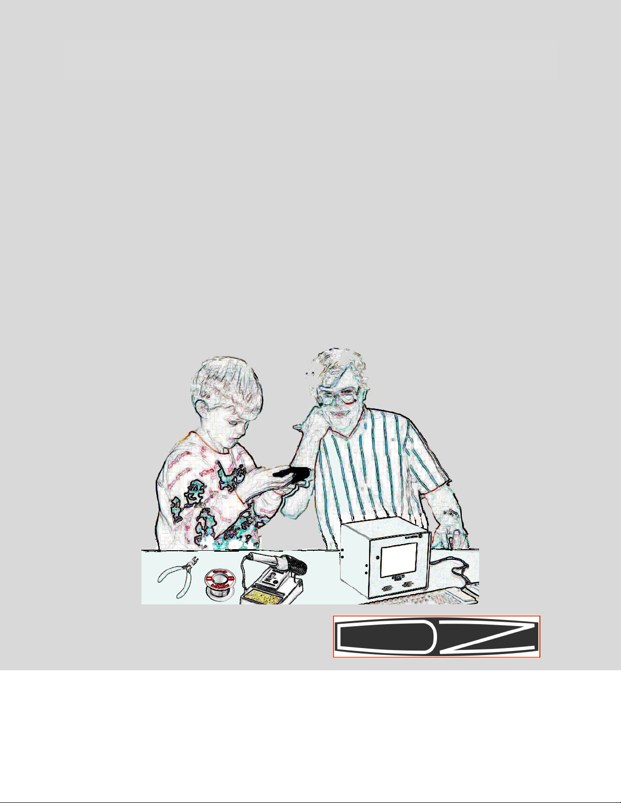
Most kit builders find it helpful to sepa-
rate the parts into categories for quick
identification. Muffin tins and cardboard
egg cartons serve this purpose admirably.
poor soldering jobs. Please
take a moment to familiarize
yourself with proper soldering
technique. And do not, under
ANY circumstances, use corro-
sive (“acid-core”) solder!
That will void your warranty
and render your kit inopera-
tive. Also be sure to avoid
the use of products that may
be called solder but are real-
ly glue (e.g., LePage's Liquid
Solder, nothing more than me-
tallic-grey colored airplane
glue).
8. Soldering should only be done
in an area with good ventila-
tion and with a properly heat-
ed soldering iron.
9. Resistors are identified by
their values in Ohms, Kilohms
(K) or Megohms (M) and by col-
or codes. Your kit uses resis-
tors of several types. Axial
leaded resistors have color
coded bands on them. For 5%
resistors, the first two bands
represent the numeric value
and the third band represents
a multiplier, which is a power
of 10. Thus, a 56 Ohm resistor
is Green-Blue-Black. A 10KOhm
resistor is Brown-Black-
Orange, and so on. The fourth
band is the tolerance — no
band represents 20%, a silver
band 10%, and a gold band 5%.
Your Saguaro uses mostly one
percent or better resistors,
which have 4 bands for the
value. A 4.75K resistor is
Yellow-Violet-Green-Brown. We
have placed resistors of given
types in individual bags for
you, but should they get mixed
and you have trouble reading
the color code, we recommend
an inexpensive volt-ohmmeter
be used to check the values. A
fluorescent light is also use-
ful to “bring out” the colors,
and a magnifying glass is also
handy.
10.Capacitors are identified by
their type — disk, polysty-
rene, polypropylene, electro-
lytic, trimmer, etc. — and ca-
pacitance values are in micro-
farads (uF) or picoFarads
(pF). Polarized types have the
positive pin marked on the
silkscreen and also have a
square pad.
11.Inductors are represented ei-
ther by their inductance in
nanoHenries (nH), microHenries
(uH), milliHenries (mH) or by
the number of turns in the
coil if you are doing the
winding.
12.Diodes are marked with a band
on the cathode end. The PC
boards have a bar silkscreened
across one side of the compo-

Page 7
nent outline and a square pad
which identifies the cathode.
13.Transistors have either a tab
or a flat side that you can
match to the silkscreened com-
ponent outline. Most transis-
tors will need to have their
leads “sprung” a little to fit
in the holes. Do so carefully
to avoid breaking the leads
off.
14.ICs have a notch, beveled side
and/or a dot representing the
side containing pin 1. When
you hold an IC with the notch
or the beveled side up, pin 1
is in the upper left corner.
The silkscreened outlines on
the board all have notches and
pin 1 also has a square pad.
15.To insert an IC, rest the IC
on its side on a hard surface
Slowly roll the entire chip so
that all the leads on that
side are bent inward at once
and the same distance. Do
about half what appears to be
required. Check the leads
against the socket or PCB and
then roll the other side in-
ward the same way.
16.It is CRITICAL that you mount
polarized parts correctly!
Double check your work to be
sure that all such parts match
the photos. See Detail 1.
Detail 1. Identifying polarity of
diodes, transistors, ICs and po-
larized capacitors.
Transistor — Flat side
Diode — band on cathode
IC — pin 1 (through-hole part)
IC—pin 1 (SMT part)
Electrolytic capacitors — negative side

Page 8
Abbreviations and definitions of terms used in this manual:
PC = Personal Computer
PCB = Printed Circuit Board
PH = Panhead
FH = Flathead
M/S = Machine Screw (typically M2.5, M3, M5 sizes)
P/L = Patch lock (material added to threads to help screws stay in)
PCB-mt = Printed Circuit Board mounting
AMP MTA = Tyco Electronics connector with .1” pin spacing
IDC = Insulation Displacement Connector (MTA connectors are IDC type)
Ribbon cable = Flat cable with connectors on each end
Header = PCB-mounted connector
CA = Cable Assembly
A word about what lies ahead…
This manual is designed to allow you to build confidence in your kit-
building ability as you go along. You start by adding parts to the
chassis and then building and installing the controller board. You
will then be able to turn on the power and measure some voltages be-
fore loading ICs that could be damaged if the voltages are wrong. This
will give you confidence that the kit-building is progressing normal-
ly. You will also be able to use a PC to help you locate parts on the
boards using the PCB layout files that we have included. The project
concludes with integration of the circuit boards and cables into the
chassis. So let’s get started!
NOTE: Your kit includes ten feet of specially formulated no-lead, no-
clean Alpha Telecore solder. This should be enough to complete your
kit. It uses a tin, silver and copper alloy, and a non-aggressive
flux that does not require cleaning. DO NOT USE FLUX REMOVER OR WATER
after building the circuit board. It will leave a gummy residue.

Page 9
The steps involved in building a kit are listed below. Be sure to fol-
low them and you will have a lot of fun building, testing and using
your kit.
1. Check off parts as loaded. Each board kit contains a list of parts
used on that board. We have checked off each part on the right side
of the page as it is inserted in the bag. As you remove a part from
the bag and load it on the board, cross out its “reference designa-
tor” (e.g., “R1”) on the left side of the page. Our method of bag-
ging parts is different from all other kit vendors and will make
the task much faster and less error prone. If you are missing any
parts, call or email us and we’ll rush replacements immediately.
2. Parts have been pre-sorted. Do not remove parts from the bags until
called for, to avoid mixing parts up (especially resistors).
3. Find a picture online. The parts lists are also included on a flash
drive that is shipped with your kit. Almost every part has a hyper-
link to the vendor. Make sure you are connected to the Internet,
and click the part to get a picture and information about it.
4. Pay attention to soldering techniques. Keep your soldering iron
clean by using a wet sponge, use appropriate heat and maintain heat
long enough to make good solder joints. Solder problems are the
number one cause of problems when building kits, so do it right!
5. Some boards have been pre-loaded with surface mount parts. Be care-
ful not to flex these boards to avoid having parts snap off.
6. Take your time! We know you want to get it done and start using it,
but doing it wrong will only delay that moment. Before you start,
set up a ventilated, static-free work area with enough room to
build the kit. Prepare parts bins and get the tools you will need.
If you’re tired, take a break. Enjoy building your kit!
7. Make sure that you are loading the part that’s called for in the
right place. Once loaded, it can be hard to find a misloaded part.
Be especially careful to load polarized parts (connectors, ICs, di-
odes, electrolytic capacitors) in the right direction.
8. Once you’ve done a step, put a checkmark inside the parentheses in
this manual. This helps you remember where you left off when you
build in stages.
9. After you have assembled a circuit board, take a moment (just one)
to marvel at your handiwork, then spend a few more minutes critiqu-
ing it! Check for solder bridges, unsoldered or insufficiently sol-
dered connections, solder blobs, loose screws and electronic parts,
reversed polarized components, etc. Sometimes it helps to have a
friend check your work.
Kit-Building Procedures

Page 10
Your safety is of utmost importance to us. Please read this infor-
mation before you get started, and remember these rules as you contin-
ue building and testing your Saguaro.
1. Always have a healthy respect for electricity. The voltages present
inside the Saguaro can be as high as 260VAC, and high currents are
available (up to 2 Amps DC). Use a power supply with overcurrent
foldback or crowbar protection so that in case of high currents the
supply will shut down. Set the output current only as high as nec-
essary for a given step.
2. When measuring voltages inside electronic equipment, it is general-
ly a good idea to use only one hand, wear rubber-soled shoes and
avoid areas with standing water. However, remember that slightly
humid environments can prevent static electricity that could damage
the electronic parts! Use a humidifier in dry climates.
3. Do not work on powered electronics by yourself if at all possible.
Have a parent, spouse or friend nearby. If you must work alone,
keep a telephone handy in the event you run into problems.
4. Soldering irons are hot. They can burn your skin and cause damage
to workbenches and carpets. We recommend you use one with an auto-
matic shutoff in case you forget to turn it off when you are done.
5. Do not work on electronic projects when you are tired. We know you
want to finish it, but accidents are more likely when you are
tired. Take breaks! Be careful!
6. Use proper ventilation in your work area. Solder contains tin and
lead (or tin and silver), and solder fumes should not be allowed to
“hover” near your work. Open a door or window, use a fan, and be
cognizant of the potential dangers.
7. When clipping leads, use eye protection and/or be sure to direct
the flying leads down into a nearby trash can. As you gain experi-
ence clipping component leads, you will learn how to clip them so
that they fall harmlessly away from the board.
8. Be careful not to cut yourself when handling sharp objects such as
connectors and sheet metal. Keep some tissues, bandages and antibi-
otic ointment nearby in the event of an injury.
9. Use common sense in dealing with unfamiliar things. If you don’t
understand something, call us or ask a friend for help.
Safety First!

Page 11
SOLDERING INSTRUCTIONS
Poor soldering accounts for almost all kit building problems. The pho-
tographs below show examples of the most common types of bad solder
connections and a good one. If you locate any of these bad solder con-
nections in your kit, correct them as described. Study this section
carefully before you start building your kit.
Use a good quality, variable tem-
perature soldering iron with a
conical, narrow tip, and set the
temperature to 800 degrees F. We
provide 10’ of recommended solder
in each kit. Keep the sponge damp
and wipe the tip on the sponge
before each solder step.
Solder joint problems. Solution:
Remove solder with a wick or sol-
der sucker (see below), and re-
heat the connection, touching the
iron to both the component lead
and the pad at the same time.
Solder bridge.
Solder that stretches from one
trace or pad to another creates a
short circuit. Solution: Hold the
board upside down and reheat the
area. The excess solder will flow
down the soldering iron. Another
solution is to use a “solder
sucker” or solder wick to remove
excess solder. Solder suckers
work well one or two times on a
given connection. After that,
they can lift pads off the board.
Good solder connections. A good
solder connection looks like
this. Solder flows evenly onto
both the part and the PC board or
chassis component. It is shiny
and even, not lumpy and dull.
Component leads that are properly
soldered can not be moved in the
hole. The component lies flat on
the board.

Page 12
STATIC PRECAUTIONS
Many of the components in your
kit can be damaged by exposure to
static electricity. Please read
this page to familiarize yourself
with the causes of and solutions
to this problem.
When the climate is dry, you can
generate thousands of volts simp-
ly by walking across a carpet.
When you then touch a metal ob-
ject you can feel the effects of
this as you draw a spark! That
same spark, often too small to
see or feel, can destroy sensi-
tive electronic components. You
MUST take precautions when work-
ing with electronics to prevent
damage.
The best solution is to outfit
your workbench with anti-static
devices — floormats, grounded
soldering irons, and work mats
with grounded wrist straps. If
these are not practical for you,
the very least you should do is
to discharge yourself to ground
after you sit down and before you
touch any electronic items, by
touching a grounded object such
as the corner of a wall.
In a dry environment, simply
standing up after sitting in a
non-grounded chair can also
charge you with electricity. If
you stand up to stretch, for ex-
ample, be sure to re-ground your-
self before getting back to work.
Don’t wear insulated sole shoes
and avoid nylon, wool or other
static-producing material in your
clothing.
If your work area floor is car-
peted, spray fabric softener on
it using a hand spray bottle.
Fabric softener is conductive and
will bleed away carpet static for
a few hours.
Don’t use a plastic table unless
you have a grounded work mat on
it. Use a wood or metal table if
possible.
Pets are notorious for inducing
static into your work area. Don’t
allow them anywhere near your
workbench!
All electronic components are
susceptible to static, but semi-
conductors and assembled boards
containing semiconductors are the
most prone to damage. These in-
clude diodes (including light-
emitting diodes [LEDs]), transis-
tors and integrated circuits
(ICs).
You are a walking lightning
bolt! Be careful!

Page 13
Chassis Parts
2 6 5
16
7
15 13
3 4
11
17
8
1
10 14 12
9
Please check each item to make sure it is present in the right quantity. Let us know
right away if it’s not so that we can ship replacements.
Bag Item Description Vendor Vendor P/N Bin Qty
1 1 Hardware M5 Washer 18-8 SS McMaster 98689A114 B1 2
1 2 Hardware M5 Wingnut, 18-8 SS McMaster 94545A225 B2 1
1 3 Hardware M5 KEPS nut 18-8 SS McMaster 90923A222 B3 3
1 4 Hardware M5 x 16mm PH Phillips M/S SS McMaster 90116A256 B4 1
1 5 Hardware M2.5 x 20mm PH Phillips M/S Patch SS McMaster 95911A612 B5 2
1 6 Hardware M2.5 x 6mm PH Philips M/S SS McMaster 90116A110 B6 2
1 7 Hardware M2.5 Internal tooth lockwasher SS McMaster 93925A220 B7 2
1 8 Hardware M3 x 6mm FH Philips Black Metric M/S SS McMaster 91698A302 B8 4
1 9 Hardware M3 x 6mm PH Philips M/S Patch SS McMaster 95911A211 B9 7
1 10 Hardware M3 x 6mm PH Philips SEMS M/S SS McMaster 90402A702 B10 12
1 11 Hardware M3 x 10mm PH Philips M/S Patch SS McMaster 95911A218 B13 4
1 12 Hardware M5 x 12mm FH M/S SS McMaster 91801A256 B14 2
1 13 Hardware M3 KEPS nut McMaster 90923A216 B15 4
1 14 Hardware M3 7.5mm plastic spacer Digikey 145-13ME022-ND B16 4
1 15 Hardware M2.5 12.45mm Nylon spacer Digikey 907-490 B17 2
1 16 Hardware 4-40 x 3/8" PH Philips M/S Patch SS McMaster 96562A108 834 4
1 17 Hardware #10 Solder lug Mouser 534-913 510 1
1 18 Thermalsil insulator for TO-220 Mouser 532-53-77-4ACG 523 2
1 19 Shoulder washer Mouser 532-7721-7PPS 303 2
1 20 Unthreaded Bumper, SBR Rubber, 5/8" OD, 9/32" High McMaster 9540K52 140 4
1 21 Hardware Washer flat rubber for M5 screw McMaster 99604A143 B32 4
18 19 20 21

Page 14
24 25 26
27 28
Bag Item Description Vendor Vendor P/N Bin Qty
2 22 Knob .5in dia matte finish indicator line top/side Allied 70206941 146A 2
2 23 Knob 1.75in dia glossy finish finger dimple no line Heilind AMP 3-1437622-8 147 1
3 24 Encoder optical RPG 5V 128ppr 1/4in shaft w/nut Newark ENA1J-B28-L00128L 176 1
3 25 Switch on/off rocker Mouser DM22J12S205PQ B26 1
3 26 Resistor variable panel mount 10K Ohm Mouser 313-1000F-10K B27 2
3 27 Headphone jack—1/4” stereo, with swiches Mouser 523-ACJS-MN-5 B35 1
3 28 Connector 2.1mm panel mount Mouser 502-721A B36 1
3 29 Fuse - 1/2A 250V 3AG AGC Mouser 504-BK/AGC-1/2-R B45 2
4 30 MicroSD card with Raspbian OS and custom software DZKit S0074-10102 B38 1
4 31 USB memory stick (manual, ExpressPCB layouts) DZKit S0074-10103 B39 1
4 32 Saguaro serial number sticker BW Ind. S0074-00501 B40 1
5 33 No-clean .020" Alpha 143090 Lead-free Telecore Solder Technimark Alpha 143090 B41 10'
5 34 Heat shrink tubing - 1/8" black Mouser 602-221V018-4 B42 12"
5 35 Heat shrink tubing - 3/16" gray Mouser 562-Q2-CB3/1612SS500 740 12"
5 36 Hardware Cable tie - 0.1 x 3.9" Mouser 571-2-160967-1 526 2
5 37 Tool hex-key .05in Wiha 35410 96A 1
5 38 Tool hex-key 1/16in Wiha 35411 96B 1
6 30 Tool Knurled nut fastener 6mm for 3.5mm minijacks Full Compass NT500 96D 1
22 23
29 30 31
32 33 34 35
36
37 38 39

Page 15
42 40 41
49
43
44 45
47 48
50 51
Item Loose/Heavy parts Vendor Vendor P/N Bin Qty
40 Transformer Triad VPS16-1600 16VCT 1.6A Mouser 553-VPS16-1600 B25 1
41 Power entry module filtered Mouser 631-FN372-2/22 B28 1
42 Display 7 inch TFT Resistive HDMI Matrix Orbital HTT70A-IPS B30 1
43 Fan with Heatsink for Rpi GeeekPi ZP-0110 B33 1
44 Speaker 8 ohm 3W 200Hz-20kHz Mouser 243-FR10HM-8OHM B34 1
45 Circuit board kit DZKit S0074-40001 B37 1
47 Chassis DZKit S0074-00001 B46 1
48 Top Cover DZKit S0074-00002 B47 1
49 Lexan overlay DZKit S0074-00003 B31 1
50 Plastic safety shield DZKit S0074-00004 B48 1
51 Plastic alignment tooling pins DZKit S0074-00005 B49 2
46 Cable kit DZKit S0074-70001 B50 1
46

Page 16
Chassis Cables
S0074-00101: Bag of loose wires. Cut each color wire to the noted
length, strip to 3/16” and tin. Extra wire has been provided. If
you make a mistake and there isn’t enough remaining of the desired
color, it is OK to use a different color, but be sure to keep
track of what you used where.
Wire color Wire length
White 8"
Wht/Gray 8"
Black 8"
Wht/Blk 8"
Blue 2"
Blue 2"
Blue 3.5"
Wht/Blue 3.5"
Red 8"
Red 3"
Wht/Red 3"
Wht/Red 2"
Brown 2"
Brown 2"
Yellow 6"
Yellow 6"
Green 3.5"
S0074-00102: Controller wiring harness

Page 17
Chassis Cables, continued
S0074-00103: Controller to Display Power
S0074-00104: Controller to Speaker/Headphones kit
S0074-00105: Controller to Pi GPIO
S0074-00106: Pi audio to controller
S0074-00107: Controller to Pi power
S0074-00114: Controller to Pi fan
(shown with heat shrink tubing attached)
S0074-00108: Pi to HDMI display

Page 18
Optional Parts
S0074-00112-1: SDRPlay RSP1A for use inside Saguaro only. Case must
be removed and board attached to standoffs inside chassis.
S0074-00115-1 or –2: Raspberry Pi 4B with either 4G (-1) or 8G
(-2) of RAM . Not sold separately. (Required option)
S0074-00112-2: 8” USB-A to USB-B

Page 19
Optional parts
S0074-00110/111 Touch interface
S0074-00109 Ext HDMI interface
S0074-00116 WiFi Keyboard/Mouse
S0074-00113-1
AC Power cord and international adapters
Note: Wireless USB
receiver is located
inside battery
compartment of mouse
S0074-00113-2 18AWG Heavy
Duty Power Cord, 3.3ft
(1m) 10 Amps 120V Black

Page 20
General chassis layout
SDR
Raspberry Pi 4B
Micro-SD card
Controller
Display
RPG
On/off switch
Pots
Headphone jack
Loudspeaker
Safety shield
Transformer
AC Power Entry Module
Ground lug
DC Power In
DIY expansion
board
This manual suits for next models
1
Table of contents
Popular Receiver manuals by other brands

Golze Engineering
Golze Engineering ADL140 Connecting manual

Tremetrics
Tremetrics 900A Operating and service manual

PS Engineering
PS Engineering PAV80 Installation and operation manual

Marantz
Marantz 2325 Service manual

Fanimation
Fanimation SW70 installation instructions

Sony
Sony STR-DA5300ES - Multi Channel Av Receiver operating instructions