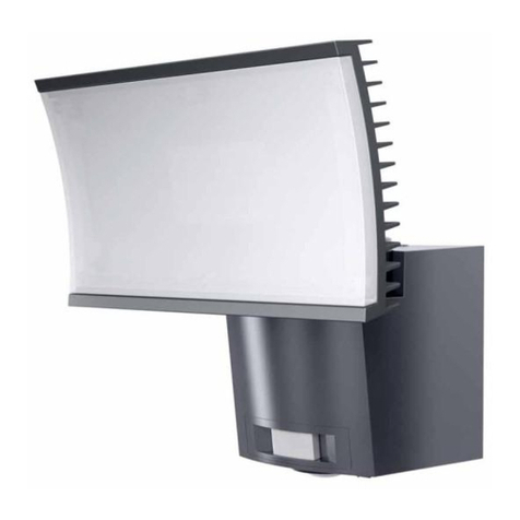
e-conolight E-MS Series User manual

Document: Date
Created By: ECO#
LPN00321X0001A1_A 2016-8-22
TMT 006368
INSTALLATION INSTRUCTIONS
E-MS Series
www.e-conolight.com | 888.243.9445 | FAX: 262.504.5409
CAUTIONS
IMPORTANT SAFEGUARDS
When using electrical equipment, basic safety
precautions should always be followed including the
following:
READ AND FOLLOW ALL
SAFETY INSTRUCTIONS
1. DANGER- Risk of shock- Disconnect power before
installation.
DANGER – Risque de choc – Couper l’alimentation
avant l’installation.
2. This luminaire must be installed in accordance with the
NEC or your local electrical code. If you are not familiar
with these codes and requirements, consult a qualied
electrician.
Ce produit doit être installé conformément à NEC ou votre
code électrique local. Si vous n’êtes pas familier avec ces
codes et ces exigences, veuillez contacter un électricien
qualié.
3. Suitable for Wet Locations.
Adspte pour les Endroits Mouiles.
4. Wall mount and covered ceiling mount only.
Installation murale et sur plafond couvert seulement.
SAVE THESE INSTRUCTIONS
FOR FUTURE REFERENCE
1. Loosen and remove (2) screw nuts from xture canopy. Remove
the mounting plate from the xture. See Figure 1.
2. Route supply leads through the center of the mounting plate.
Attach mounting plate to the junction box using supplied screws.
See Figure 2:
3. Make the following wire connections using supplied wire nuts:
a. Connect supply ground to xture ground (green).
b. Connect supply common to xture neutral (white) lead.
c. Connect supply 120VAC black to xture black (line) lead.
d. Push all leads into the junction box.
4. Position the xture and mounting canopy with silicon pad over the
studs on the mounting plate. See Figure 3.
NOTE: For wet locations, caulk between rear mounting gasket
and mounting surface to prevent water from entering xture from
behind. A high grade caulking material such as silicone rubber
should be used.
5. Reattach screw nuts that were removed in Step 1. See Figure 3:
FIXTURE INSTALLATION
Mounting plate
Fixture
Wire nut
Screws for secure
the mounting plate
Screw Nut
FIGURE 1
Notes:
1. Fixture is intended to operate at 120 VAC only.
2. Fixture is intended to be mounted over 3" or 4" octagon recessed
junction box, supplied by customer.
3. There should be no items shielding the detection window which
could result in an inability of the sensor to detect motion.
4. There should be no continuously moving objects in front of the
detection window which could result in false triggering.
5. Avoid installing fixture near air conditioning or heating equipment
to prevent frequent unintended cycling.
Mounting plate
Screws for secure
the mounting plate
FIGURE 2
Fixture
Mounting
Plate
Screw Nut
FIGURE 3

Document: Date
Created By: ECO#
LPN00321X0001A1_A 2016-8-22
TMT 006368
INSTALLATION INSTRUCTIONS
E-MS Series
www.e-conolight.com | 888.243.9445 | FAX: 262.504.5409
1. Loosen adjustment knobs on xture heads and sensor knuckles.
Aim xture heads and sensor. Retighten adjustment knobs to
maintain desired aiming angle.
NOTE: Ensure power is off before proceeding.
1. Turn the sensitivity setting knob (SENS) fully clockwise to the
maximum setting.
2. Turn the time setting knob (TIME) fully counter clockwise to the
minimum setting.
3. Turn the ambient light setting knob (LUX) fully clockwise to the
maximum or daylight position.
4. Supply power to the xture. Fixture will take approximately 30
seconds to turn on.
5. Proceed to Setting of Occupancy Sensor
SETTINGS OF OCCUPANCY SENSOR
NOTE: Complete Sensor Initialization Procedure before setting up the
sensor.
1. The sensitivity setting (SENS) knob can be adjusted to control the
motion detection distance. The minimum setting is approximately
15 feet from the sensor and the maximum setting is approximately
40 feet.
2. The time setting (TIME) is used to set the delay time that the light
will stay on for after motion is no longer detected. The minimum
setting is approximately 10 seconds and the maximum setting is
approximately 10 minutes.
3. The ambient light setting (LUX) is used to control the ambient
light level at which the sensor becomes active. If set in the “sun”
position (max.) the motion sensor will allow the xture to operate at
all times (day and night). The “sun” position is usually appropriate
when setting the sensitivity, since sensitivity adjustments are
usually made during the day.
• If in the “moon” position (min), the sensor will only allow the
xture to turn on at night when totally dark (no stray light from
other sources present).
• A setting approximately midway between the “sun” and “moon”
positions should be used to allow the xture to come on at
night in the presence of some background light (other security
lights, streetlights, etc.) while still, remaining off during the day.
If xture turns on when there is too much day light still present,
rotate ambient light setting slightly towards the “moon” position.
If xture does not operate or operates inconsistently, rotate
ambient light setting slightly towards “sun” position.
FIXTURE ADJUSTMENTS
SENSOR INITIALIZATION PROCEDURE- SEE
FIGURE 4
CAUTION: Changes or modications not expressly approved could
void your authority to use this equipment.
This device complies with part 15 of the FCC Rules. Operation is
subject to the following two conditions: (1) This device may not cause
harmful interference, and (2) this device must accept any interference
received, including interference that may cause undesired operation.
Changes or modications not expressly approved could void your
authority to use this equipment.
This equipment has been tested and found to comply with the limits
for a Class B digital device, pursuant to part 15 of the FCC Rules.
These limits are designed to provide reasonable protection against
harmful interference in a residential installation. This equipment
generates, uses and can radiate radio frequency energy and, if not
installed and used in accordance with the instructions, may cause
harmful interference to radio communications. However, there is no
guarantee that interference will not occur in a particular installation. If
this equipment does cause harmful interference to radio or television
reception, which can be determined by turning the equipment off and
on, the user is encouraged to try to correct the interference by one or
more of the following measures:
—Reorient or relocate the receiving antenna.
—Increase the separation between the equipment and receiver.
—Connect the equipment into an outlet on a circuit different from that to
which the receiver is connected.
—Consult the dealer or an experienced radio/TV technician for help.
CAN ICES-003 (B)/NMB-003 (B)
FCC NOTICE
1. The light does not turn on.
• Check to ensure that wiring connections are correct
• Make sure power is turned on.
2. The sensitivity is not functioning as expected.
• Make sure nothing is shielding the detection window of the
sensor
• Make sure there are not continuously moving objects in the eld
of view of the sensor which are resulting in false triggering.
3. The xture remains on continuously.
• Check to make sure there are no continuously moving objects in
the sensor’s eld.
• Shorten time setting. Verify that time delay is not set to
maximum.
• Verify that input is 120VAC
• Verify that xture is not installed near air conditioning or heating
equipment.
TROUBLESHOOTING PERFORMANCE ISSUES
FIGURE 4
Table of contents
Other e-conolight Floodlight manuals
