E.F. Johnson Company 8500 Series User manual
8500 Series
FM Portable Radio
Multi-Net®
Intrinsically-Safe
Viking CK
OPERATING
MANUAL
FM
Approved

SAFETY INFORMATION
2
SAFETY INFORMATION
The FCC has adopted a safety standard for human exposure to RF energy. Proper
operation of this radio under normal conditions results in user exposure to RF
energy below the Occupational Safety and Health Act and Federal Communica-
tion Commission limits.
WARNING
•DO NOT allow the antenna to touch or come in very close proximity with the
eyes, face, or any exposed body parts while the radio is transmitting.
•DO NOT operate the radio in explosive or flammable atmospheres. The trans-
mitted radio energy could trigger blasting caps or cause an explosion.
•DO NOT operate the radio without the proper antenna installed.
•DO NOT allow children to operate or play with this radio.
•DO NOT operate this transceiver in flammable or explosive atmospheres that
are not listed on the label on the back of the transceiver.
•DO NOT use battery packs other than Intrinsically Safe Battery Packs, Part
No. 587-8565-162 (1400 mAH) or 587-8560-160 (1000 mAH).
•DO NOT remove, install, or recharge the battery pack while in a hazardous
location.
•DO NOT dispose of the battery pack in fire because it may explode.
•DO NOT open this transceiver or permit it to be serviced by anyone that is not
authorized by the Factory Mutual Research Corporation to repair EFJohnson
intrinsically safe radios.
•DO NOT use unapproved accessories with this transceiver.
NOTE: The above warning list is not intended to include all hazards that may be
encountered when using this radio.
This device complies with Part 15 of the FCC rules. Operation is subject to the
condition that this device does not cause harmful interference. In addition,
changes or modifications to this equipment not expressly approved by the E.F.
Johnson Company could void the user’s authority to operate this equipment
(FCC rules, 47CFR Part 15.19).

LAND MOBILE PRODUCT WARRANTY - The manufacturer’s
warranty statement for this product is available from your product
supplier or from the E.F. Johnson Company, 299 Johnson Avenue, Box
1249, Waseca, MN 56093-0514. Phone (507) 835-6222.
Copyright© 1999 by the E.F. Johnson Company
The E.F. Johnson Company, which was founded in 1923, designs, manu-
factures, and markets radio communication products, systems, and
services worldwide. E.F. Johnson produces equipment for land mobile
radio and mobiletelephone services which include business, industrial,
government, public safety, and personal users.
Viking Head/EFJohnson logo, Multi-Net®, LTR®, and Call Guard® are
registered trademarks of the E.F. Johnson Company. All other company
and/or product names used in this manual are trademarks and/or
registered trademarks of their respective manufacturer.
BATTERY RECYCLING INFORMATION
If a Nickel-Cadmium (Ni-Cd) battery is used by this radio,
it must be recycled or disposed of properly when it reaches
the end of its life. It may be illegal to dispose of this battery
in the municipal waste stream. For information on how to
dispose of this battery properly, call toll free
1-800-8-BATTERY (1-800-822-8837).

NOTES
4
NOTES

QUICK REFERENCE GUIDE
5
QUICK REFERENCE GUIDE
Change system number: S(System)
Change group number: G (Group)
Turn system scanning on or off: SCN
Temporarily suspend system and group scanning in Multi-Net or LTR
mode: Press Auxiliary switch on side.
Lock out of scanning last-selected system or group: LCK
Unlock all systems: LCK for 2 seconds
Turn on backlight: Press upper switch on side.
Return to home or last active system/group: RTN
Disable or enable keypad: Turn power on with LCK pressed.
Disable or enable key press tone: Turn power on with SCN pressed.
Switch between high and low power: TurnpoweronwithRTNpressed(high
power models only).
Switch between loud and soft clear-to-talk tone: Turn power on with the “S”
key pressed.
Monitor in the conventional mode: Press Auxiliary switch on side.
Telephone Calling Using Optional Keypad
NOTE: In the phone mode, SCN=STO, LCK = CLR, and RTN = RCL.
Select phone mode: PHON or SND
Store a number in memory: STO (1-8)
Recall a number from memory: RCL (1-8)
Erase the last number in display: CLR
Erase entire number in display: RCL CLR
Display overflow digits: RCL 0
Step through numbers stored in memory: RCL
Transmit number in display: Briefly press PTT switch to acquire dial tone,
then SND.

FEATURES
6
FEATURES
•Up to 14 systems selectable
•Up to 11 groups selectable per system (Multi-Net)
•Up to 10 channels selectable per system (conventional)
•System scan
•Group scan (Multi-Net Only)
•System and group lockout when scanning
•LCD display with backlight to indicate system and group numbers, 7-
character system or 5-character group identifier, and other information
•Both Multi-Net (trunked) and conventional (non-trunked) operation
•Repeater talk-around in conventional mode
•Optional keypad for making telephone calls
•When equipped with the optional keypad, up to 8 telephone numbers
can be stored in memory and later recalled. Each number can contain
up to 14 digits
•Call indicator
•Clear-to-talk beep to signal when speaking can begin (Multi-Net Only)
•Compatible with optional Vehicle Adapter and Remote Control Unit to
allow mobile (vehicle) as well as handheld use
NOTE: Programming by your system operator determines the specific
operation of some of the preceding features. Refer to separate descrip-
tions in this manual for more information.

TABLE OF CONTENTS
7
TABLE OF CONTENTS
SAFETY INFORMATION ..................................2
QUICK REFERENCE GUIDE...............................5
FEATURES ..............................................6
CONTROLS..............................................9
DISPLAY INFORMATION.................................12
STANDARD CALLS......................................14
Introduction ...........................................14
PlacingaStandardCall ..................................14
ReceivingaStandardCall ................................14
SPECIAL CALLS ........................................15
Introduction ...........................................15
PlacingaSpecialCall....................................15
ReceivingaSpecialCall..................................16
Landside-OriginatedCalls................................17
Additional Phone Mode Information . . . .....................17
SUPERVISORY TONES ..................................19
InterceptTone..........................................19
Clear-To-TalkTone.....................................20
KeyPressTone.........................................20
ConfirmationTone......................................20
CallProceedTone ......................................20
EndCallTone..........................................21
ProceedDialingTone....................................21
SYSTEM SCAN..........................................21
General...............................................21
ScanResumeDelay.....................................22
TransmittingInScan ....................................22
SystemandGroupLockout...............................23
ScanningMulti-NetSystems..............................24
Scanning Conventional Systems . . .........................24
OTHER FEATURES......................................24
Clear-To-Talk..........................................24
GroupScan............................................25
Time-OutTimer........................................25
CallIndicator..........................................25
RTN(Return)Key......................................26

TABLE OF CONTENTS
8
EmergencyButton......................................26
TransmitInhibit........................................27
PriorityCalls...........................................27
KeypadDisable ........................................27
KeyPressToneDisable..................................28
High/LowPowerSelect..................................28
MULTI-NET AND CONVENTIONAL MODES................29
General...............................................29
ChannelMonitoring.....................................29
SupervisoryTones......................................29
GroupSelect...........................................29
CONVENTIONAL MODE OPERATION .....................30
MonitoringBeforeTransmitting ...........................30
TransmitDisableWhenBusy..............................30
Receive-OnlyandTalk-AroundChannels....................31
CallGuardSquelch......................................31
OPERATION WITH OPTIONAL REMOTE CONTROL UNIT...32
Introduction ...........................................32
ControlUnitControls....................................33
MiscellaneousOperatingInformation.......................34
SendingStatusInformation ...............................36
MISCELLANEOUS INFORMATION ........................36
Auto-Registration.......................................36
BusyQueuing..........................................37
SystemOperatorProgramming............................37
SettingVolumeLevel....................................38
DisplayMessages.......................................38
RechargeableBatteryPack................................39
Speaking Into Microphone . . ..............................41
OperationAtExtendedRange.............................41
FCCLicensing.........................................41
TransceiverService .....................................42
INTRINSICALLY SAFE CLASSIFICATION..................42
Introduction ...........................................42
ClassificationofAreas(Division)..........................43
Classification of Atmospheres (Class/ Group). ................43
CONTROLS
9
CONTROLS
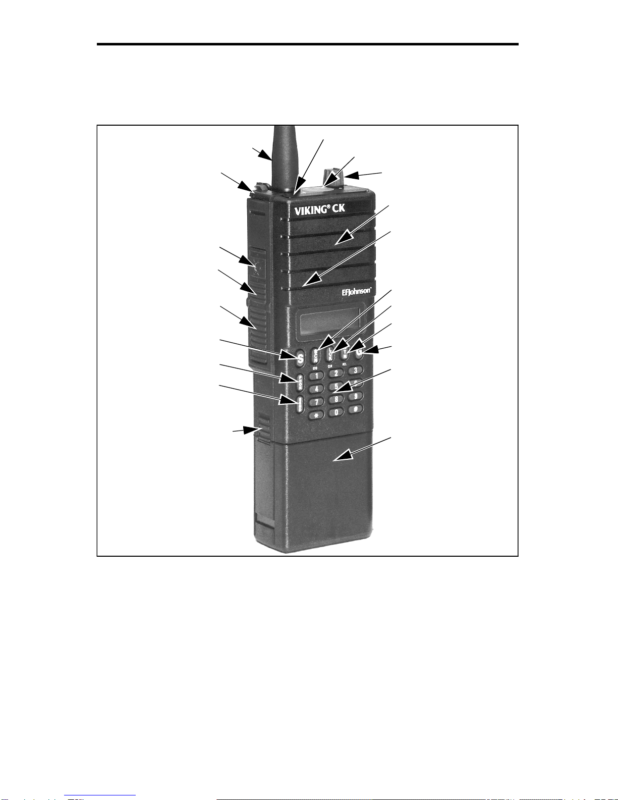
FRONT PANEL CONTROLS
On-Off/Volume -Turning this knob clockwise turns power on and sets
the volume. Turning it counterclockwise to the detent turns power off.
Power is on when information appears in the display. Refer to “Setting
Volume Level” on page 38 for more information.
Emergency Button - This switch is used to manually or automatically
place a high priority call. Refer to “Emergency Button” on page 26 for
more information.
Transmit Indicator
Emergency Button
On-Off/Volume
Speaker
Microphone
Scan Key (Store)
Lock Key (Clear)
Return Key (Recall)
Group Select
Telephone Keypad
Battery Pack
Battery Release
Button
Send Key
Phone Mode Select
System Select
Push-To-Talk
Switch
Auxiliary Switch
Backlight Switch
Accessory
Antenna
Connector

CONTROLS
10
S (System) - Pressing this key increases the selected system. Holding it
down causes the function to repeat. Only programmed systems can be
selected. Turning power on with this switch pressed changes the loudness
of the clear-to-talk tone.
G (Group) - Pressing this key increases the selected group. Holding it
down causes the function to repeat. Only programmed groups can be
selected.
SCN (Scan) - Turns the scan feature on and off. Scan is enabled when
“SCN” is indicated in the lower part of the display. Scanning is actually
occurring when “IN SCAN” is indicated in the upper part of the display.
Turning power on with this key pressed enables/disables the key press
tone.
LCK (Lock) - Used to lock systems out of the scan list so that they are
not scanned. Also adds locked out systems or groups back into the scan
list. Pressing this key changes the status of whatever system or group was
selected last. The system or group is locked out and not scanned if is
indicated next to “SYS” or “GRP”. Turning power on with this switch
pressed enables/disables the keypad.
RTN (Return) - Is programmed to select either the home or last active
system/group.
Push-To-Talk (PTT) Switch - Pressing this switch turns the transmitter
on as indicated by in the display and a lighted transmit indicator on
the top panel. This switch is the lower half of the rubber switchpad on the
side.
Auxiliary Switch - Pressing this switch with a Multi-Net system selected
temporarily suspends system or group scanning. Pressing it twice halts
scanning until it is again pressed twice or scanning is re-enabled by the
SCN key. Pressing it with a conventional system selected enables the
monitor mode. This switch is the lower part of the upper half of the
rubber switchpad on the side.
TX

CONTROLS
11
Backlight Switch - Pressing this switch illuminates the display so that it
can be viewed in low-light conditions. This switch is the upper part of the
upper half of the rubber switchpad on the side.
Speaker and Microphone - The internal speaker and microphone are
located behind the grille in the locations shown.
Battery Pack - Rechargeable nickel-cadmium (Ni-Cd) battery pack.
OPTIONAL KEYS FOR TELEPHONE CALLS
NOTE: Refer to “SPECIAL CALLS” on page 15 for more information on
the following keys.
Telephone Keypad - 0-9, *, and # keys for dialing the telephone number.
PHON (Phone) - Turns the phone mode on and off.
SND (Send) - This switch can be used instead of the PHON key to select
the phone mode. The system and group preprogrammed for telephone
calls are then automatically selected. Pressing this switch after the phone
mode is selected transmits the telephone number in the display.
NOTE: The next three keys are dual-function keys which operate as
follows when the phone mode is selected and as described in the
preceding information when the standard mode is selected.
STO (SCN) - Pressing this key and then a number key from 1-8 stores
the number in the display in that memory location.
CLR (LCK) - Pressing this key erases the last digit in the display.
Holding this key down causes function to repeat. Pressing RCL and then
CLR erases the entire number.
RCL (RTN) - Pressing this key steps through the numbers stored in
memory. Pressing this key and then the number of a memory location
from 1-8 recalls the telephone number stored in that location.

DISPLAY INFORMATION
12
DISPLAY INFORMATION
FRONT PANEL DISPLAY
System Display - Indicates the selected system number.
Group Display - Indicates the selected group number.
SYS (System) - Always displayed above the system number.
GRP (Group) - Always displayed above the group number.
SCN (Scan) - Indicates that the scan mode has been selected by the SCN
key.
CALL - Indicates that a call has been received and not answered. To turn
this indicator off, press any key except backlight.
(SYS) - This indication next to “SYS” indicates that the displayed
system has been locked out of scanning by the LCK key. This indication
appears while scanning if any system has been locked out of the scan list.
(GRP) - This indication next to “GRP” indicates that the displayed
group has been locked out of the scan list by the LCK key. This indica-
RCLCLRSTO
GS N
S
CK
L
CT
N
R
SYS SCN
MUTE PHON
BUSYCALLMON
GRP Group
Display
Alphanumeric Display
System
Display

DISPLAY INFORMATION
13
tion appears when system or group scanning if any group has been locked
out of the scan list.
MUTE - Indicates that the key press tone has been muted by turning
power on with the SCN key pressed. To re-enable this tone, turn power
on again with the SCN key pressed.
TX - Indicates that the transmitter is on. This indication appears in
conjunction with the red transmit indicator next to the antenna.
BUSY - Indicates that the channel is busy when a conventional system is
selected.
MON - When a conventional system is selected, indicates that the
monitor mode has been enabled by pressing the Auxiliary switch on the
side. This disables Call Guard® squelch so that all messages are heard.
Press the Auxiliary switch again to disable monitoring.
PHON - Indicates that the phone mode has been selected by pressing the
PHON or SND key (telephone keypad models only).
- Indicates that the displayed group is programmed for telephone
calls.
- Indicates that the battery needs recharging.
- Indicates that there are overflow digits because the telephone
number is longer than 7 digits. To momentarily display the overflow
digits, press RCL 0.
Alphanumeric Display - In the standard (non-phone) mode, this display
indicates either the 7-character system identification or the 5-character
group identification. Programming determines which is displayed, and
the group identification is available on Multi-Net systems only. In the
phone mode, this display indicates the telephone number. Operating
modes and error conditions may also be indicated by this display as
described in “Display Messages” on page 38.

STANDARD CALLS
14
STANDARD CALLS
Introduction
Most calls that you make to others in your radio system are standard
calls. When these calls are placed, all that is required is to select the
desired system and group. No number needs to be entered on the tele-
phone keypad as with special calls. Calls in the conventional mode are
always standard calls.
Placing a Standard Call
1. Turn power on and set the volume as required.
2. Select the desired system and group if applicable.
3. If a conventional system is selected, the channel must be monitored
before transmitting. Refer to page 30 for more information.
4. Press the push-to-talk switch on the side of the transceiver and begin
talking. If a Multi-Net system is selected, a clear-to-talk tone sounds to
indicate when the system has been successfully accessed and speaking
can begin. Refer to “Clear-To-Talk Tone” on page 20 for more
information.
5. Release the push-to-talk switch as soon as the message is complete and
listen for a response. The push-to-talk switch must be pressed to talk
andreleasedtolisten.
Receiving a Standard Call
1. Turn power on and set the volume level as required.
2. Select the desired system and group if applicable.
3. After the message is received, press the push-to-talk switch on the side
of the transceiver and respond. This switch must be pressed to talk and
released to listen. If scanning, you should respond before scanning

SPECIAL CALLS
15
resumes which is programmable for 1-7 seconds after the message
ends. If you do not, another call may be received and you may have to
change the system and group. Refer to “Transmitting In Scan” on
page 22 for more information.
SPECIAL CALLS
Introduction
Special calls include telephone calls, calls to specific mobiles or a
dispatcher, calls to other Multi-Net sites, and others. These calls differ
from standard calls in that a special number must be dialed after the
system is accessed. This number is dialed using the optional DTMF
keypad on the front panel of the transceiver.
NOTE: Special calls can be placed and received only if your transceiver
has been programmed for that service by your system operator.
Placing a Special Call
1. Turn power on and set the volume level as required.
2. Select the system and group programmed for the special call you are
making. When a group programmed for telephone calls is selected, the
handset symbol appears in the display.
3. Select the phone mode by pressing the PHON or SND keys. The phone
mode is indicated by “PHONE” in the display.
4. If youare making a telephone call, dialthe telephonenumber. If you are
making other calls, a number containing 4-8 digits is dialed. Your
system operator will tell you what number you are to dial for each
special call you can make. You may also be able to recall the number
from memory as described in the following information.
5. Momentarily press the push-to-talk switch to acquire a dial tone. Then
press the SND key to transmit the number in the display. Release the

SPECIAL CALLS
16
push-to-talk switch (if it is pressed) and a short tone should sound to
indicate that the call was accepted by the system. After this tone
sounds, a ringing or second short tone sounds as follows:
A ringing tone indicates that the other party is being rung. If it is a tele-
phone call and the line is busy, a busy tone may also sound. In this case,
terminate the call by pressing the # key. When the party answers,
continue the call as described in step 6.
A second short tone indicates that the path is complete and you should
transmit your message. No ringing of the otherparty occurs. Proceed as
follows:
6. Pressthepush-to-talkswitchtotalkandreleaseittolistenaswithstan-
dard calls. Since the path is one way, you will not hear the other party
while the push-to-talk switch is pressed.
7. When the conversation is finished, the call should be terminated by
sending the # character. This character is sent automatically when you
exit the phone mode by pressing the PHON key. It can also be sent by
pressing the # key. Three beeps indicate that the call has been
terminated.
Receiving a Special Call
1. Turn power on and set the volume level as required.
2. Special calls are usually received regardless of the group selected if a
system programmed for Multi-Net operation is selected or scanned.
However, some calls may require that a certain system and group be
selected. If so, your system operator will tell you which to select.
3. When “ringing” is heard, answer the call in the normal manner (press
the push-to-talk switch to talk and release it to listen). It is not necessary
to select the phone mode to receive a special call.
4. When the call is finished, it is usually terminated by the originating
party. If you do not hear the three rapid beeps which indicate termina-
tion, press the # key to terminate the call.

SPECIAL CALLS
17
Landside-Originated Calls
Mobiles can also be called from a landside telephone. If the system
is designed so that mobiles can be called directly, simply dial the tele-
phone number of the mobile being called. If mobiles cannot be called
directly, dial the number of the system. Then when the system answers,
dial the special number which specifies the mobile being called. This
number is supplied by your system operator, and it must be dialed using a
tone-type telephone. Depending on the type of call, a ringing tone then
sounds or a second tone sounds which indicates speaking can begin.
Operation is similar to that described in “Placing a Special Call” on
page 15.
Additional Phone Mode Information
Phone Mode
When the phone mode is selected by pressing the PHON or SND
keys, “PHONE” appears in the lower part of the display and the group or
system identification is cleared so that the phone number can be
displayed. In addition, the SCN, LCK, and RTN keys become STO, CLR,
and RCL keys. Group scan is also disabled if it is programmed, causing
calls to be received on the displayed group only. To exit the phone mode,
press the PHON key (the SND key cannot be used).
When the phone mode is not selected, the number keys dial a
number only when the push-to-talk switch is pressed. In addition, the
dialed number does not appear in the display, so it cannot be stored or
recalled. When the phone mode is exited, any phone number in the
display is erased and cannot be redisplayed unless it was stored in
memory. The transceiver always goes into the standard mode when
power is turned on.
Entering the phone mode using the PHON or SND key results in
slightly different operation. When the PHON key is used, the displayed
system and group do not change when entering as well as exiting the
phone mode. When the SND key is used, the system and group prepro-
grammed for telephone calls are automatically selected when the phone

SPECIAL CALLS
18
mode is entered. Then when the phone mode is exited by pressing the
PHON key, the system and group that were displayed when the phone
mode was entered are again displayed. The system and group may be
changed in either mode by pressing the SYS or GRP keys.
Dialing The Number
The phone mode allows you to enter the telephone or mobile number
at any convenient rate, correct any dialing errors, and then transmit the
number when desired by pressing the SND (Send) key. To erase the last
digit entered, press CLR. Holding the key down erases the number one
digit at a time. To erase the entire number, press RCL CLR.
Numbersupto14digitsinlengthcanbeenteredinthismode.
However, only the last 7 digits are displayed. When there are overflow
digits, an arrow appears on the left side of the telephone number. To
momentarily display the overflow digits, press RCL 0. The RCL key can
also be used to step through the programmed telephone numbers,
including overflow digits.
Numbers can be dialed in the phone mode without changing the
number in the display. Simply dial the number while the push-to-talk
switch is pressed. This also allows access to special services which
require numbers to be dialed after the connection is made. Telephone
calls can also be placed without selecting the phone mode by dialing the
number with the push-to-talk switch pressed.
Storing and Recalling Telephone Numbers From Memory
Up to 8 telephone or other numbers can be stored in memory and
then later recalled. This eliminates the need to re-enter frequently called
numbers. Each of these numbers can be up to 14 digits in length. To store
a number, select the phone mode and enter the telephone number as
described in the preceding section. Then press STO and a number key
from 1-8 to select the memory location where the telephone number is
stored. The * symbol can be stored, but is sent normally without a pause.
If the # symbol is stored, it will terminate the call when it is sent. To
recall a telephone number, press RCL and then the memory location from

SUPERVISORY TONES
19
1-8. The number can then be changed if necessary and then transmitted
by pressing SND.
Telephone numbers can also be programmed by your system oper-
ator. A unique identification can then be stored in the unused positions of
each 14-character location. For example, if the number has seven digits,
the seven-character identification “RICHARD” can be stored with the
number. Then when the number is recalled, “RICHARD” is flashed in the
display followed by his telephone number. Each number programmed by
your system operator can also be programmed so that you cannot change
it. If you do change a number with a unique identification, the identifica-
tion is erased and cannot be reprogrammed from the keypad. You must
take the transceiver back to your system operator to have the identifica-
tion reprogrammed.
Terminating a Call
When a conversation is finished, it is good practice for one of the
parties to terminate the call by transmitting the # character. When the
phone mode is exited by pressing the PHON key, this character is sent
automatically. The # key can also be pressed to send this character. Three
beeps sound to indicate that the system has detected the end of the call.
Terminating the call in this manner prevents additional billing that may
occur for the time it takes the system to automatically detect the end of a
call.
SUPERVISORY TONES
NOTE: The following tones are heard at various times when operating
this transceiver. The tones are heard only when a Multi-Net system is
selected unless noted otherwise.
Intercept Tone
This is a siren-like tone (alternating high and low tones) which indi-
cates the following error conditions:

SUPERVISORY TONES
20
•If this tone sounds after the transmit indicator flashes several times and
“NO SITE” appears in the display, an out-of-radio-range condition is
indicated. To complete a call, you may need to get closer to your radio
system. Once this tone sounds, no more access attempts are made until
the push-to-talk switch is released and then pressed again.
•If this tone sounds after the transmitter has been on for an extended
period and “TX TIME” also appears in the display, the transmitter has
been disabled by the time-out timer feature. Refer to page 25 for more
information.
•Ifthistonesoundsas soonasthepush-to-talk switchispressedand“TX
DSBL” appears in the display, a channel is selected in the conventional
mode that is programmed as receive-only. Refer to page 31 for more
information.
Clear-To-Talk Tone
This is a short tone which sounds when the push-to-talk switch is
pressed. It indicates that the system has been successfully accessed and
speaking can begin. This tone does not sound if the radio system is busy
or if the selected system is programmed for conventional operation. Refer
to “Clear-To-Talk” on page 24 for more information.
Key Press Tone
This is a short tone that sounds when a key is pressed. This tone can
be enabled and disabled by turning power on with the SCN key pressed.
NOTE: The following tones are heard only when making telephone calls.
Confirmation Tone
This is a short tone that sounds when the number just dialed is
accepted by the system.
This manual suits for next models
1
Table of contents
Other E.F. Johnson Company Portable Radio manuals

E.F. Johnson Company
E.F. Johnson Company 51 Series User manual

E.F. Johnson Company
E.F. Johnson Company 5100 Series User manual

E.F. Johnson Company
E.F. Johnson Company 7243 LTR-NET User manual

E.F. Johnson Company
E.F. Johnson Company 5100 Series Reference guide

E.F. Johnson Company
E.F. Johnson Company 5100 ES User manual

E.F. Johnson Company
E.F. Johnson Company 5100 ES User manual

E.F. Johnson Company
E.F. Johnson Company 002-8170-001 User manual

E.F. Johnson Company
E.F. Johnson Company 4100 SERIES User manual

E.F. Johnson Company
E.F. Johnson Company 5100 Series User manual

E.F. Johnson Company
E.F. Johnson Company MULTI-NET II User manual


