E.F. Johnson Company 5100 ES User manual

5100 ES Series Portable Radio
Service Manual
UHF / 700 / 800 MHz
Project 25 Conventional and Trunked
Analog and Digital Conventional
SMARTNET®/SmartZone®
7.2 VDC
4 Watt (UHF), 2.5 Watt (700 MHz), 3 Watt (800 MHz)
Part Number 001-5100-60001
January 2007


Copyright ©2007 by the E.F. Johnson Company
The EFJohnson logo, PC Configure™, Trunked IP25™, and Call Guard®are trademarks of EFJohnson. All
other company and/or product names used in this manual are trademarks and/or registered trademarks of
their respective manufacturers.
Information in this manual is subject to change without notice.
5100 ES Series Portable Radio Service Manual
January 2007


January 2007 5100 ES Series Portable Radio Service Manual i
Table of Contents
1 General Information 1-1
Scope of Manual. . . . . . . . . . . . . . . . . . . . . . . . . . . . . . . . . . . . . . . . . . . . . . . . . . . . . . . . . . . . . . . . 1-1
Radio Description. . . . . . . . . . . . . . . . . . . . . . . . . . . . . . . . . . . . . . . . . . . . . . . . . . . . . . . . . . . . . . . 1-2
General. . . . . . . . . . . . . . . . . . . . . . . . . . . . . . . . . . . . . . . . . . . . . . . . . . . . . . . . . . . . . . . . . . . 1-2
Analog/Digital Operation. . . . . . . . . . . . . . . . . . . . . . . . . . . . . . . . . . . . . . . . . . . . . . . . . . . . . . 1-3
Operating Protocols . . . . . . . . . . . . . . . . . . . . . . . . . . . . . . . . . . . . . . . . . . . . . . . . . . . . . . . . . 1-3
Systems, Channels, and Zones . . . . . . . . . . . . . . . . . . . . . . . . . . . . . . . . . . . . . . . . . . . . . . . . 1-3
Systems. . . . . . . . . . . . . . . . . . . . . . . . . . . . . . . . . . . . . . . . . . . . . . . . . . . . . . . . . . . . . . 1-3
Channels . . . . . . . . . . . . . . . . . . . . . . . . . . . . . . . . . . . . . . . . . . . . . . . . . . . . . . . . . . . . . 1-4
Zones. . . . . . . . . . . . . . . . . . . . . . . . . . . . . . . . . . . . . . . . . . . . . . . . . . . . . . . . . . . . . . . . 1-4
Programming. . . . . . . . . . . . . . . . . . . . . . . . . . . . . . . . . . . . . . . . . . . . . . . . . . . . . . . . . . . . . . . 1-4
Alignment . . . . . . . . . . . . . . . . . . . . . . . . . . . . . . . . . . . . . . . . . . . . . . . . . . . . . . . . . . . . . . . . . 1-4
Part Number Breakdown . . . . . . . . . . . . . . . . . . . . . . . . . . . . . . . . . . . . . . . . . . . . . . . . . . . . . . . . . 1-5
Transceiver Identification . . . . . . . . . . . . . . . . . . . . . . . . . . . . . . . . . . . . . . . . . . . . . . . . . . . . . . . . 1-6
Accessories . . . . . . . . . . . . . . . . . . . . . . . . . . . . . . . . . . . . . . . . . . . . . . . . . . . . . . . . . . . . . . . . . . . 1-6
Intrinsically Safe Information . . . . . . . . . . . . . . . . . . . . . . . . . . . . . . . . . . . . . . . . . . . . . . . . . . . . . 1-9
Introduction. . . . . . . . . . . . . . . . . . . . . . . . . . . . . . . . . . . . . . . . . . . . . . . . . . . . . . . . . . . . . . . . 1-9
Definitions. . . . . . . . . . . . . . . . . . . . . . . . . . . . . . . . . . . . . . . . . . . . . . . . . . . . . . . . . . . . . . . . 1-10
Possible Ignition Sources . . . . . . . . . . . . . . . . . . . . . . . . . . . . . . . . . . . . . . . . . . . . . . . . . . . . 1-10
Intrinsically Safe and Nonincendive Ratings. . . . . . . . . . . . . . . . . . . . . . . . . . . . . . . . . . . . . . 1-11
Classification of Hazardous Areas and Atmospheres. . . . . . . . . . . . . . . . . . . . . . . . . . . . . . . 1-11
Classification of Hazardous Areas (Division). . . . . . . . . . . . . . . . . . . . . . . . . . . . . . . . . 1-12
Atmosphere Classification (Class/Group) . . . . . . . . . . . . . . . . . . . . . . . . . . . . . . . . . . . 1-12
Secure Communication . . . . . . . . . . . . . . . . . . . . . . . . . . . . . . . . . . . . . . . . . . . . . . . . . . . . . . . . . 1-13
Typical Performance Specifications. . . . . . . . . . . . . . . . . . . . . . . . . . . . . . . . . . . . . . . . . . . . . . . 1-14
2 Battery, Accessory and Disassembly Information 2-1
Battery Information . . . . . . . . . . . . . . . . . . . . . . . . . . . . . . . . . . . . . . . . . . . . . . . . . . . . . . . . . . . . . 2-1
Battery Removal/Installation. . . . . . . . . . . . . . . . . . . . . . . . . . . . . . . . . . . . . . . . . . . . . . . . . . . 2-1
Battery Charging. . . . . . . . . . . . . . . . . . . . . . . . . . . . . . . . . . . . . . . . . . . . . . . . . . . . . . . . . . . . 2-2
Preventing Loss of Encryption Keys. . . . . . . . . . . . . . . . . . . . . . . . . . . . . . . . . . . . . . . . . . . . . 2-2
Battery Care . . . . . . . . . . . . . . . . . . . . . . . . . . . . . . . . . . . . . . . . . . . . . . . . . . . . . . . . . . . . . . . 2-2
Belt Clip Installation. . . . . . . . . . . . . . . . . . . . . . . . . . . . . . . . . . . . . . . . . . . . . . . . . . . . . . . . . . . . . 2-3
5100 ES Series Portable Radio
Service Manual
January 2007

ii 5100 ES Series Portable Radio Service Manual January 2007
Table of Contents (continued)
Accessory Installation . . . . . . . . . . . . . . . . . . . . . . . . . . . . . . . . . . . . . . . . . . . . . . . . . . . . . . . . . . . 2-3
Option Select Lines. . . . . . . . . . . . . . . . . . . . . . . . . . . . . . . . . . . . . . . . . . . . . . . . . . . . . . . . . . 2-4
Transceiver Disassembly. . . . . . . . . . . . . . . . . . . . . . . . . . . . . . . . . . . . . . . . . . . . . . . . . . . . . . . . . 2-5
Separating Front Cover and Chassis . . . . . . . . . . . . . . . . . . . . . . . . . . . . . . . . . . . . . . . . . . . . 2-5
Removing RF and Logic Boards From Chassis . . . . . . . . . . . . . . . . . . . . . . . . . . . . . . . . . . . . 2-6
Removing UI (User Interface) Board. . . . . . . . . . . . . . . . . . . . . . . . . . . . . . . . . . . . . . . . . . . . . 2-7
Removing Switch Assembly . . . . . . . . . . . . . . . . . . . . . . . . . . . . . . . . . . . . . . . . . . . . . . . . . . . 2-7
3Operation 3-1
General . . . . . . . . . . . . . . . . . . . . . . . . . . . . . . . . . . . . . . . . . . . . . . . . . . . . . . . . . . . . . . . . . . . . . . . 3-1
4 Transceiver Programming 4-1
Programming Setup. . . . . . . . . . . . . . . . . . . . . . . . . . . . . . . . . . . . . . . . . . . . . . . . . . . . . . . . . . . . . 4-1
Computer Description . . . . . . . . . . . . . . . . . . . . . . . . . . . . . . . . . . . . . . . . . . . . . . . . . . . . . . . . . . . 4-2
Using the PC Configure Software. . . . . . . . . . . . . . . . . . . . . . . . . . . . . . . . . . . . . . . . . . . . . . . . . . 4-2
Firmware Upgrade Instructions . . . . . . . . . . . . . . . . . . . . . . . . . . . . . . . . . . . . . . . . . . . . . . . . . . . 4-2
Upgrade Utility Compatibility. . . . . . . . . . . . . . . . . . . . . . . . . . . . .. . . . . . . . . . . . . . . . . . . . . . 4-2
Firmware Upgrade instructions. . . . . . . . . . . . . . . . . . . . . . . . . . . . . . . . . . . . . . . . . . . . . . . . . 4-3
Requirements . . . . . . . . . . . . . . . . . . . . . . . . . . . . . . . . . . . . . . . . . . . . . . . . . . . . . . . . . 4-3
PC Configure Upgrade Instructions. . . . . . . . . . . . . . . . . . . . . . . . . . . . . . . . . . . . . . . . . 4-4
Initial Setup . . . . . . . . . . . . . . . . . . . . . . . . . . . . . . . . . . . . . . . . . . . . . . . . . . . . . . . . . . . 4-4
Firmware Upgrade Procedure. . . . . . . . . . . . . . . . . . . . . . . . . . . . . . . . . . . . . . . . . . . . . 4-5
Cloning Procedure . . . . . . . . . . . . . . . . . . . . . . . . . . . . . . . . . . . . . . . . . . . . . . . . . . . . . . . . . . . . . . 4-6
5 Circuit Description 5-1
General Overview. . . . . . . . . . . . . . . . . . . . . . . . . . . . . . . . . . . . . . . . . . . . . . . . . . . . . . . . . . . . . . . 5-1
Introduction. . . . . . . . . . . . . . . . . . . . . . . . . . . . . . . . . . . . . . . . . . . . . . . . . . . . . . . . . . . . . . . . 5-1
PC Boards. . . . . . . . . . . . . . . . . . . . . . . . . . . . . . . . . . . . . .. . . . . . . . . . . . . . . . . . . . . . 5-1
Analog Mode. . . . . . . . . . . . . . . . . . . . . . . . . . . . . . . . . . . . . . . . . . . . . . . . . . . . . . . . . . . . . . . 5-2
Receive Mode . . . . . . . . . . . . . . . . . . . . . . . . . . . . . . . . . . . . . . . . . . . . . . . . . . . . . . . . . 5-2
Transmit Mode. . . . . . . . . . . . . . . . . . . . . . . . . . . . . . . . . . . . . . . . . . . . . . . . . . . . . . . . . 5-2
Project 25 Digital Mode. . . . . . . . . . . . . . . . . . . . . . . . . . . . . . . . .. . . . . . . . . . . . . . . . . . . . . . 5-3
Receive Mode . . . . . . . . . . . . . . . . . . . . . . . . . . . . . . . . . . . . . . . . . . . . . . . . . . . . . . . . . 5-3
Transmit Mode. . . . . . . . . . . . . . . . . . . . . . . . . . . . . . . . . . . . . . . . . . . . . . . . . . . . . . . . . 5-3
UHF Low RF Board. . . . . . . . . . . . . . . . . . . . . . . . . . . . . . . . . . . . . . . . . . . . . . . . . . . . . . . . . . . . . . 5-3
Receiver . . . . . . . . . . . . . . . . . . . . . . . . . . . . . . . . . . . . . . . . . . . . . . . . . . . . . . . . . . . . . . . . . . 5-5
Front End Bandpass Filter. . . . . . . . . . . . . . . . . . . . . . . . . . . . . . . . . . . . . . . . . . . . . . . . 5-5
Front End LNA and Bypass Switching. . . . . . . . . . . . . . . . . . . . . . . . . . . . . . . . . . . . . . . 5-5
Post-LNA Bandpass Filters . . . . . . . . . . . . . . . . . . . . . . . . . . . . . . . . . . . . . . . . . . . . . . . 5-5
Mixer and LO Filter . . . . . . . . . . . . . . . . . . . . . . . . . . . . . . .. . . . . . . . . . . . . . . . . . . . . . 5-5
IF Filter and Amplifier . . . . . . . . . . . . . . . . . . . . . . . . . . . . . . . . . . . . . . . . . . . . . . . . . . . 5-5
Back End IC. . . . . . . . . . . . . . . . . . . . . . . . . . . . . . . . . . . . . . . . . . . . . . . . . . . . . . . . . . . 5-6

January 2007 5100 ES Series Portable Radio Service Manual iii
Table of Contents (continued)
Synthesizer. . . . . . . . . . . . . . . . . . . . . . . . . . . . . . . . . . . . . . . . . . . . . . . . . . . . . . . . . . . . . . . . 5-6
PLL IC . . . . . . . . . . . . . . . . . . . . . . . . . . . . . . . . . . . . . . . . . . . . . . . . . . . . . . . . . . . . . . . 5-6
Reference Oscillator . . . . . . . . . . . . . . . . . . . . . . . . . . . . . .. . . . . . . . . . . . . . . . . . . . . . 5-7
Analog Switches and PLL Loop Filters . . . . . . . . . . . . . . . . . . . . . . . . . . . . . . . . . . . . . . 5-7
VCOs. . . . . . . . . . . . . . . . . . . . . . . . . . . . . . . . . . . . . . . . . . . . . . . . . . . . . . . . . . . . . . . . 5-7
Transmitter . . . . . . . . . . . . . . . . . . . . . . . . . . . . . . . . . . . . . . . . . . . . . . . . . . . . . . . . . . . . . . . . 5-7
Modulation. . . . . . . . . . . . . . . . . . . . . . . . . . . . . . . . . . . . . . . . . . . . . . . . . . . . . . . . . . . . 5-7
Power Amplifier . . . . . . . . . . . . . . . . . . . . . . . . . . . . . . . . . . . . . . . . . . . . . . . . . . . . . . . . 5-7
ALC . . . . . . . . . . . . . . . . . . . . . . . . . . . . . . . . . . . . . . . . . . . . . . . . . . . . . . . . . . . . . . . . . 5-8
T/R Switching and Harmonic Filter . . . . . . . . . . . . . . . . . . .. . . . . . . . . . . . . . . . . . . . . . 5-8
700/800 MHz RF Board. . . . . . . . . . . . . . . . . . . . . . . . . . . . . . . . . . . . . . . . . . . . . . . . . . . . . . . . . . . 5-8
Receiver . . . . . . . . . . . . . . . . . . . . . . . . . . . . . . . . . . . . . . . . . . . . . . . . . . . . . . . . . . . . . . . . . 5-10
Front End Bandpass Filter. . . . . . . . . . . . . . . . . . . . . . . . . . . . . . . . . . . . . . . . . . . . . . . 5-10
Front End LNA and Bypass Switching. . . . . . . . . . . . . . . . . . . . . . . . . . . . . . . . . . . . . . 5-10
Post-LNA Bandpass Filters . . . . . . . . . . . . . . . . . . . . . . . . . . . . . . . . . . . . . . . . . . . . . . 5-10
Mixer and LO Filter . . . . . . . . . . . . . . . . . . . . . . . . . . . . . . .. . . . . . . . . . . . . . . . . . . . . 5-10
IF Filter and Amplifier . . . . . . . . . . . . . . . . . . . . . . . . . . . . . . . . . . . . . . . . . . . . . . . . . . 5-11
Back End IC. . . . . . . . . . . . . . . . . . . . . . . . . . . . . . . . . . . . . . . . . . . . . . . . . . . . . . . . . . 5-11
Synthesizer. . . . . . . . . . . . . . . . . . . . . . . . . . . . . . . . . . . . . . . . . . . . . . . . . . . . . . . . . . . . . . . 5-12
PLL IC . . . . . . . . . . . . . . . . . . . . . . . . . . . . . . . . . . . . . . . . . . . . . . . . . . . . . . . . . . . . . . 5-12
Reference Oscillator . . . . . . . . . . . . . . . . . . . . . . . . . . . . . .. . . . . . . . . . . . . . . . . . . . . 5-12
Analog Switches and PLL Loop Filters . . . . . . . . . . . . . . . . . . . . . . . . . . . . . . . . . . . . . 5-12
VCOs. . . . . . . . . . . . . . . . . . . . . . . . . . . . . . . . . . . . . . . . . . . . . . . . . . . . . . . . . . . . . . . 5-12
Transmitter . . . . . . . . . . . . . . . . . . . . . . . . . . . . . . . . . . . . . . . . . . . . . . . . . . . . . . . . . . . . . . . 5-13
Modulation. . . . . . . . . . . . . . . . . . . . . . . . . . . . . . . . . . . . . . . . . . . . . . . . . . . . . . . . . . . 5-13
Power Amplifier . . . . . . . . . . . . . . . . . . . . . . . . . . . . . . . . . . . . . . . . . . . . . . . . . . . . . . . 5-13
ALC . . . . . . . . . . . . . . . . . . . . . . . . . . . . . . . . . . . . . . . . . . . . . . . . . . . . . . . . . . . . . . . . 5-13
T/R Switching and Harmonic Filter . . . . . . . . . . . . . . . . . . .. . . . . . . . . . . . . . . . . . . . . 5-13
User Interface Board . . . . . . . . . . . . . . . . . . . . . . . . . . . . . . . . . . . . . . . . . . . . . . . . . . . . . . . . . . . 5-14
Power Supplies. . . . . . . . . . . . . . . . . . . . . . . . . . . . . . . . . . . . . . . . . . . . . . . . . . . . . . . . . . . . 5-14
MPC870 Processor. . . . . . . . . . . . . . . . . . . . . . . . . . . . . . . . . . . . . . . . . . . . . . . . . . . . . . . . . 5-15
Flash Memory. . . . . . . . . . . . . . . . . . . . . . . . . . . . . . . . . . . . . . . . . . . . . . . . . . . . . . . . . . . . . 5-15
SRAM . . . . . . . . . . . . . . . . . . . . . . . . . . . . . . . . . . . . . . . . . . . . . . . . . . . . . . . . . . . . . . . . . . . 5-15
HPI Bus Multiplexer. . . . . . . . . . . . . . . . . . . . . . . . . . . . . . . . . . . . . . . . . . . . . . . . . . . . . . . . . 5-16
Bus Configuration Logic . . . . . . . . . . . . . . . . . . . . . . . . . . . . . . . . . . . . . . . . . . . . . . . . . . . . . 5-16
HC08 Microcontroller . . . . . . . . . . . . . . . . . . . . . . . . . . . . . . . . . . . . . . . . . . . . . . . . . . . . . . . 5-16
SPI Flash. . . . . . . . . . . . . . . . . . . . . . . . . . . . . . . . . . . . . . . . . . . . . . . . . . . . . . . . . . . . . . . . . 5-16
Audio Out . . . . . . . . . . . . . . . . . . . . . . . . . . . . . . . . . . . . . . . . . . . . . . . . . . . . . . . . . . . . . . . . 5-17
Audio In. . . . . . . . . . . . . . . . . . . . . . . . . . . . . . . . . . . . . . . . . . . . . . . . . . . . . . . . . . . . . . . . . . 5-17
Logic Board. . . . . . . . . . . . . . . . . . . . . . . . . . . . . . . . . . . . . . . . . . . . . . . . . . . . . . . . . . . . . . . . . . . 5-19
Power Supplies. . . . . . . . . . . . . . . . . . . . . . . . . . . . . . . . . . . . . . . . . . . . . . . . . . . . . . . . . . . . 5-19
Digital. . . . . . . . . . . . . . . . . . . . . . . . . . . . . . . . . . . . . . . . . . . . . . . . . . . . . . . . . . . . . . . 5-20
Analog . . . . . . . . . . . . . . . . . . . . . . . . . . . . . . . . . . . . . . . . . . . . . . . . . . . . . . . . . . . . . . 5-20
RF Deck. . . . . . . . . . . . . . . . . . . . . . . . . . . . . . . . . . . . . . . . . . . . . . . . . . . . . . . . . . . . . 5-20
DSP. . . . . . . . . . . . . . . . . . . . . . . . . . . . . . . . . . . . . . . . . . . . . . . . . . . . . . . . . . . . . . . . . . . . . 5-20
Control Interface . . . . . . . . . . . . . . . . . . . . . . . . . . . . . . . . .. . . . . . . . . . . . . . . . . . . . . 5-21
Transmit Operation . . . . . . . . . . . . . . . . . . . . . . . . . . . . . . . . . . . . . . . . . . . . . . . . . . . . 5-21
Receive Operation. . . . . . . . . . . . . . . . . . . . . . . . . . . . . . . . . . . . . . . . . . . . . . . . . . . . . 5-21
HPI Bus Multiplexer. . . . . . . . . . . . . . . . . . . . . . . . . . . . . . . . . . . . . . . . . . . . . . . . . . . . . . . . . 5-22
Codec . . . . . . . . . . . . . . . . . . . . . . . . . . . . . . . . . . . . . . . . . . . . . . . . . . . . . . . . . . . . . . . . . . . 5-22
SEM Module . . . . . . . . . . . . . . . . . . . . . . . . . . . . . . . . . . . . . . . . . . . . . . . . . . . . . . . . . . . . . . 5-23

iv 5100 ES Series Portable Radio Service Manual January 2007
Table of Contents (continued)
6 Alignment Procedure 6-1
PC Tune. . . . . . . . . . . . . . . . . . . . . . . . . . . . . . . . . . . . . . . . . . . . . . . . . . . . . . . . . . . . . . . . . . . . . . . 6-1
7 Troubleshooting 7-1
Start Up Failure LED Indications. . . . . . . . . . . . . . . . . . . . . . . . . . . . . . . . . . . . . . . . . . . . . . . . . . . 7-1
User Troubleshooting . . . . . . . . . . . . . . . . . . . . . . . . . . . . . . . . . . . . . . . . . . . . . . . . . . . . . . . . . . . 7-2
Low Battery Indicators. . . . . . . . . . . . . . . . . . . . . . . . . . . . . . . . . . . . . . . . . . . . . . . . . . . . . . . . . . . 7-2
Battery Replacement. . . . . . . . . . . . . . . . . . . . . . . . . . . . . . . . . . . . . . . . . . . . . . . . . . . . . . . . . 7-2
Additional Information. . . . . . . . . . . . . . . . . . . . . . . . . . . . . . . . . . . . . . . . . . . . . . . . . . . . . . . . . . . 7-3
Contact Information . . . . . . . . . . . . . . . . . . . . . . . . . . . . . . . . . . . . . . . . . . . . . . . . . . . . . . . . . . . . . 7-3
8 Service Information 8-1
Product Warranty . . . . . . . . . . . . . . . . . . . . . . . . . . . . . . . . . . . . . . . . . . . . . . . . . . . . . . . . . . . . . . . 8-1
Factory Customer Service. . . . . . . . . . . . . . . . . . . . . . . . . . . . . . . . . . . . . . . . . . . . . . . . . . . . . . . . 8-2
Returns for Repairs . . . . . . . . . . . . . . . . . . . . . . . . . . . . . . . . . . . . . . . . . . . . . . . . . . . . . . . . . . . . . 8-2
Replacement Parts. . . . . . . . . . . . . . . . . . . . . . . . . . . . . . . . . . . . . . . . . . . . . . . . . . . . . . . . . . . . . . 8-3
Internet Home Page . . . . . . . . . . . . . . . . . . . . . . . . . . . . . . . . . . . . . . . . . . . . . . . . . . . . . . . . . . . . . 8-4
9 Parts List 9-1
Parts . . . . . . . . . . . . . . . . . . . . . . . . . . . . . . . . . . . . . . . . . . . . . . . . . . . . . . . . . . . . . . . . . . . . . . . . . 9-1
Exploded Views . . . . . . . . . . . . . . . . . . . . . . . . . . . . . . . . . . . . . . . . . . . . . . . . . . . . . . . . . . . . . . . 9-44
10 Schematic Diagrams and Component Layouts 10-1

January 2007 5100 ES Series Portable Radio Service Manual v
List of Figures
Figure Page
1.1 5100 ES Portable Radio Model I/II/III . . . . . . . . . .. . . . . . . . . .. . . . . . . . . .. . . . . . . . .1-1
2.1 Battery Removal . . . . . . . . . . . . . . . . . . . . . . . . . . . . . . . . . . . . . . . . . . . . . . . . . . . . . . 2-1
2.2 Belt Clip Installation . . . . . . . . . . . . . . . . . . . . . . . . . . . . . . . . . . . . . . . . . . . . . . . . . . . . 2-3
2.3 Accessory Installation . . . . . . . . . . . . . .. . . . . . . . . .. . . . . . . . . .. . . . . . . . . .. . . . . .. 2-4
4.1 Programming Setup . . . . . . . . . . . . . . . . . . . . . . . . . . . . . . . . . . . . . . . . . . . . . . . . . . . . 4-1
5.1 UHF RF Board Block Diagram . . . . . . . . . . . . . . . . . . . . . . . . . . . . . . . . . . . . . . . . . . . . 5-4
5.2 700/800 MHz RF Board Block Diagram . . . . . . . .. . . . . . . . . .. . . . . . . . . .. . . . . . . . . 5-9
5.3 User Interface Board Block Diagram . . . . . . . . . . . . . . . .. . . . . . . . . .. . . . . . . . . .. . 5-18
5.4 Logic Board Block Diagram . . . . . . . . . . . . . . . . . . . . . . . . . . . . . . . . . . . . . . . . . . . . . 5-24
6.1 Alignment Setup . . . . . . . . . . . . . . . . . . . . . . . . . . . . . . . . . . . . . . . . . . . . . . . . . . . . . . . 6-1
9.1 5100 ES Portable Radio Model III Assembly . . . . .. . . . . . . . . . . . . . . . . . . . . . . . . . . 9-44
9.2 5100 ES Portable Radio Model II Assembly . . . . . . . . . . . . . . . . . . . . . . . . . . . . . . . . . 9-45
9.3 5100 ES Portable Radio Model I Assembly . . . . .. . . . . . . . . . . . . . . . . . . . . . . . . . . . 9-46
9.4 Front Housing Assembly Model III . . . . . .. . . . . . . . . .. . . . . . . . . .. . . . . . . . . .. . . . 9-47
9.5 Front Housing Assembly Model II . . . . . . . . . . . . . . . . . . . . . . . . . . . . . . . . . . . . . . . . . 9-48
9.6 Front Housing Assembly Model I . . . . . . . . . . . . . . . . . . . . . . . . . . . . . . . . . . . . . . . . . 9-49
9.7 Rear Housing Assembly Model I/II/III . . . . . . . . . . . .. . . . . . . . . .. . . . . . . . . .. . . . . . 9-50
9.8 User Interface PCB Assembly Model III . . . . . . . .. . . . . . . .. . . . . . . . . .. . . . . . . . . . 9-51
9.9 User Interface PCB Assembly Model II . . . . . . . . . . . . . . . . . . . . . . . . . . . . . . . . . . . . 9-52
9.10 User Interface PCB Assembly Model I . . . . . . . . . . .. . . . . . . . . .. . . . . . . .. . . . . . . . 9-53
9.11 Front Cover Assembly Model II/III . . . . . . . . . . . . . . . . . . . . . . . . . . . . . . . . . . . . . . . . 9-54
9.12 Front Cover Assembly Model I . . . . . . . . . . . . . . . . . . . . . . . . . . . . . . . . . . . . . . . . . . . 9-55
9.13 Front Cover Assembly Detail . . . . . . . . . . . . . . . . . . . . . . . . . . . . . . . . . . . . . . . . . . . . 9-56
10.1 Interconnect Schematic . . . . . . . . . . . . . .. . . . . . . . . . . .. . . . . . . . . .. . . . . . . . . . . . 10-2
10.2 UHF RF Board Schematic (Page 1 of 5) . . .. . . . . . . . . . . .. . . . . . . . . .. . . . . . . . . . 10-3
10.3 UHF RF Board Schematic (Page 2 of 5) . . .. . . . . . . . . . . .. . . . . . . . . .. . . . . . . . . . 10-4
10.4 UHF RF Board Schematic (Page 3 of 5) . . .. . . . . . . . . . . .. . . . . . . . . .. . . . . . . . . . 10-5
10.5 UHF RF Board Schematic (Page 4 of 5) . . .. . . . . . . . . . . .. . . . . . . . . .. . . . . . . . . . 10-6
10.6 UHF RF Board Schematic (Page 5 of 5) . . .. . . . . . . . . . . .. . . . . . . . . .. . . . . . . . . . 10-7
10.7 UHF RF Board Layout . . . . . . .. . . . . . . . . .. . . . . . . .. . . . . . . . . .. . . . . . . . . .. . . . 10-8
10.8 700/800 MHz RF Board Schematic (Page 1 of 5) . . . .. . . . . . . . . .. . . . . . . . . .. . . . 10-9
10.9 700/800 MHz RF Board Schematic (Page 2 of 5) . . . .. . . . . . . . . .. . . . . . . . . .. . . 10-10
10.10 700/800 MHz RF Board Schematic (Page 3 of 5) . . . . . . . . . . . . . . . . . . . . . . . . . . . 10-11
10.11 700/800 MHz RF Board Schematic (Page 4 of 5) . . . . . . . . . . . . . . . . . . . . . . . . . . . 10-12
10.12 700/800 MHz RF Board Schematic (Page 5 of 5) . . . . . . . . . . . . . . . . . . . . . . . . . . . 10-13
10.13 700/800 MHz RF Board Layout . . . . . . . . . . . .. . . . . . . . . .. . . . . . . . . .. . . . . . . . . 10-14
10.14 023-5500-180/182/185 Logic Board Schematic (Page 1 of 7) . . . . . . . . . . . . . . . . . . 10-15
10.15 023-5500-180/182/185 Logic Board Schematic (Page 2 of 7) . . . . . . . . . . . . . . . . . . 10-16
10.16 023-5500-180/182/185 Logic Board Schematic (Page 3 of 7) . . . . . . . . . . . . . . . . . . 10-17
10.17 023-5500-180/182/185 Logic Board Schematic (Page 4 of 7) . . . . . . . . . . . . . . . . . . 10-18
10.18 023-5500-180/182/185 Logic Board Schematic (Page 5 of 7) . . . . . . . . . . . . . . . . . . 10-19

vi 5100 ES Series Portable Radio Service Manual January 2007
List of Figures (continued)
Figure Page
10.19 023-5500-180/182/185 Logic Board Schematic (Page 6 of 7) . . . . . . . . . . . . . . . . . .10-20
10.20 023-5500-180/182/185 Logic Board Schematic (Page 7 of 7) . . . . . . . . . . . . . . . . . .10-21
10.21 023-5500-180/182/185 Logic Board Assembly . . . . . . . . . . . . . . . . . . . . . . . . . . . . .10-22
10.22 023-5500-480/485 User Interface Board Schematic (Page 1 of 10) . . . . . . . . . . . . . .10-23
10.23 023-5500-480/485 User Interface Board Schematic (Page 2 of 10) . . . . . . . . . . . . . .10-24
10.24 023-5500-480/485 User Interface Board Schematic (Page 3 of 10) . . . . . . . . . . . . . .10-25
10.25 023-5500-480/485 User Interface Board Schematic (Page 4 of 10) . . . . . . . . . .. . .10-26
10.26 023-5500-480/485 User Interface Board Schematic (Page 5 of 10) . . . . . . . . . . . . . .10-27
10.27 023-5500-480/485 User Interface Board Schematic (Page 6 of 10) . . . . . . . . . . . . . .10-28
10.28 023-5500-480/485 User Interface Board Schematic (Page 7 of 10) . . . . . . . . . . . . . .10-29
10.29 023-5500-480/485 User Interface Board Schematic (Page 8 of 10) . . . . . . . . . .. . .10-30
10.30 023-5500-480/485 User Interface Board Schematic (Page 9 of 10) . . . . . . . . . .. . .10-31
10.31 023-5500-480/485 User Interface Board Schematic (Page 10 of 10) . . . . . . . . . . . .10-32
10.32 023-5500-480/485 User Interface Board Assembly . . . . . . . . . . . . . . . . . . . . . . . . . .10-33
10.33 023-5500-480-01/487 User Interface Board Schematic (Page 1 of 10) . . . . . . . . . . .10-34
10.34 023-5500-480-01/487 User Interface Board Schematic (Page 2 of 10) . . . . . . . . . . .10-35
10.35 023-5500-480-01/487 User Interface Board Schematic (Page 3 of 10) . . . . . . . . . . .10-36
10.36 023-5500-480-01/487 User Interface Board Schematic (Page 4 of 10) . . . . . . . . . . .10-37
10.37 023-5500-480-01/487 User Interface Board Schematic (Page 5 of 10) . . . . . . . . . . .10-38
10.38 023-5500-480-01/487 User Interface Board Schematic (Page 6 of 10) . . . . . . . . . . .10-39
10.39 023-5500-480-01/487 User Interface Board Schematic (Page 7 of 10) . . . . . . . . . . .10-40
10.40 023-5500-480-01/487 User Interface Board Schematic (Page 8 of 10) . . . . . . . . . . .10-41
10.41 023-5500-480-01/487 User Interface Board Schematic (Page 9 of 10) . . . . . . . . . . .10-42
10.42 023-5500-480-01/487 User Interface Board Schematic (Page 10 of 10) . . . . . . . . . .10-43
10.43 023-5500-480-01/487 User Interface Board Assembly . . . . . . . . . . . . . . . . . . . . . . . .10-44
10.44 Cable Schematics . . . . . . . . . . . . . . . . . . . . . . . . . . . . . . . . . . . . . . . . . . . . . . . . . . . .10-45

January 2007 5100 ES Series Portable Radio Service Manual vii
List of Tables
Table Page
1.1 Accessories . . . . . . . . . . . . . . . .. . . . . . . . . .. . . . . . . . . .. . . . . . . . . .. . . . . . . . . .. . . 1-6
1.2 Area Classification. . . . .. . . . . . . .. . . . . . . . . .. . . . . . . . . .. . . . . . . . . .. . . . . . . . . .1-12
1.3 Material Classification . . . . . . . . . . . . . . . .. . . . . . . . . .. . . . . . . . . .. . . . . . . . . .. . . . 1-12
1.4 5100 ES Portable Radio General Specifications . . . .. . . . . . . . . . . . . . . .. . . . . . . . . . 1-14
1.5 5100 ES Portable Radio Transmitter Specifications . . . . . . . . . . . . . . . . . . . . . . . . . . . 1-15
1.6 5100 ES Portable Radio Receiver Specifications . . . . . . .. . . . . . . . . .. . . . . . . . . .. . 1-15
1.7 5100 ES Portable Radio Batteries Specifications . . . . . . . . . . . . . . . . .. . . . . . . . . .. . 1-16
5.1 Multiplexer Logic Operation. . . . . . . . . . . . . . . . . . . . . . . . . . . . . . . . . . . . . . . . . . . . . . 5-16
7.1 Start Up Failure LED Indications . . . . . . . . . . . . . .. . . . . . . . . . . .. . . . . . . . . .. . . . . . . 7-1

January 2007 5100 ES Series Portable Radio Service Manual 1-1
SECTION
Chapter 1General Information
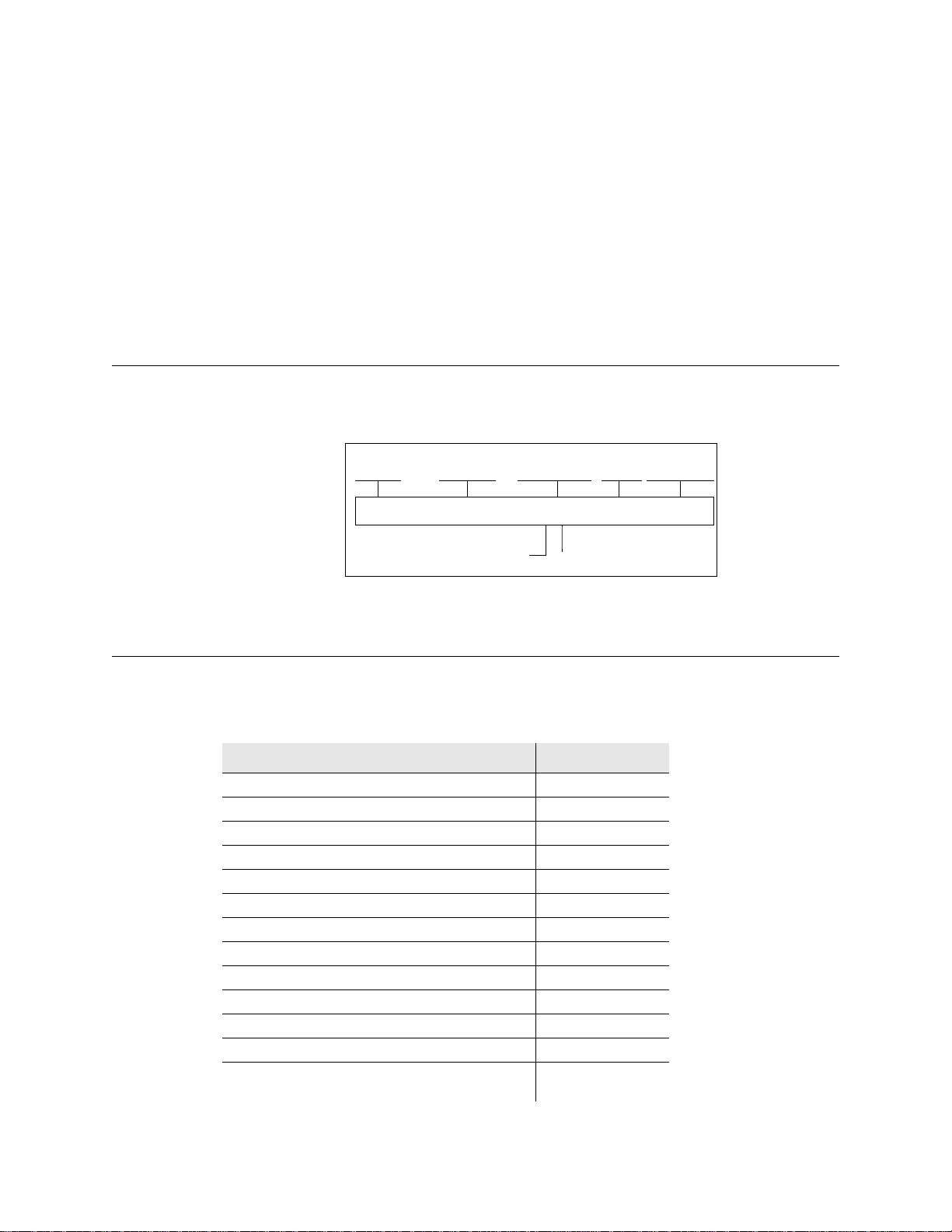
1.1 Scope of Manual
This service manual contains operation, programming, alignment, and service information
for the EFJohnson 5100 ES Portable Radio Model I/II/III.
The distinguishing characteristics of the 5100 ES Portable Radio Model I/II/III are shown
in Figure 1.1.
Figure 1.1 5100 ES Portable Radio Model I/II/III
Model IIModel I Model III

1-2 5100 ES Series Portable Radio Service Manual January 2007
General Information
5100 ES Portable Radio Model I
• Three Side Function Buttons
• No LCD Display
• No DTMF Keypad
5100 ES Portable Radio Model II
• Three Side Function Buttons
•LCDDisplay
• No DTMF Keypad
5100 ES Portable Radio Model III
• Three Side Function Buttons
•LCDDisplay
•DTMFKeypad
1.2 Radio Description
1.2.1 General
The 5100 ES portable transceivers have multiple system programming capability to allow
operation in various types of radio systems described in the following information.
Models are available for operation in the following frequency ranges. Repeater talk-
around, which allows transmitting on the receive frequency, is available with all bands.
UHF Low: 380-470 MHz
700/800 MHz: 762-806 and 806-870 MHz
800 MHz: 806-870 MHz
Power output is user switchable for low and high levels as follows:
UHF - 1 and 4 watts
700 MHz - 1 and 2.5 watts
800 MHz - 1 and 3 watts

January 2007 5100 ES Series Portable Radio Service Manual 1-3
General Information
1.2.2 Analog/Digital Operation
The 5100 ES transceiver uses a Digital Signal Processor (DSP) to provide IF and audio
filtering and modulation functions. This allows operation on the various types of channels,
backward compatibility with existing equipment, and the ability to operate on various
types of radio systems.
Narrow Band Analog - FM modulation is used with a maximum deviation of 2.5 kHz.
This mode is usually used in systems with a channel spacing of 12.5 or 15 kHz.
Wideband Analog - FM modulation is used with a maximum deviation of 5 kHz. This
mode is usually used in systems where the channel spacing is 25 kHz or 30 kHz.
Digital - C4FM modulation is used. The voice is digitized, filtered, error corrected,
optionally encrypted, and then transmitted. Operation in the Project 25 mode is always
digital, and operation in the SMARTNET/SmartZone mode can be either analog or digital.
This mode uses a channel spacing of 12.5 kHz.
1.2.3 Operating Protocols
Standard 5100 ES transceivers can be programmed for any or all the following operating
protocols. The conventional analog protocol is standard and the others are optional and
therefore must be enabled by factory programming. Refer to “Operation” on page 3-1 for
more operation information.
• APCO Project 25 (digital) conventional
• APCO Project 25 (digital) trunked
•SMARTNET
®/SmartZone®analog or digital
• Analog conventional
1.2.4 Systems, Channels, and Zones
A zone and channel are selected to place and receive calls. The following information
describes the relationship between systems, channels, and zones.
1.2.4.1 Systems
A system is a collection of channels or talk groups belonging to the same repeater site. It
defines all the parameters and protocol information required to access a site. Up to 16
systems of any type can be programmed. The maximum number of channels assignable to
a system is limited to approximately 512 with the 512 channel option (or the available
memory space as described in the following information). The 512-channel option is
typically standard with all radios.

1-4 5100 ES Series Portable Radio Service Manual January 2007
General Information
1.2.4.2 Channels
A channel selects an RF channel or talk group as follows:
Conventional Analog Mode - A channel selects a specific radio channel, Call Guard
(CTCSS/DCS) squelch coding, and other parameters unique to that channel.
Conventional Project 25 Mode - A channel selects a specific radio channel, NAC
squelch coding, talk group ID, and other parameters unique to that channel.
Trunked Project 25 Mode - A channel selects a specific talk group, announcement
group, emergency group, and other parameters unique to that talk group.
SMARTNET/SmartZone and Project 25 Trunked Operation - A channel selects a
specific talk group, announcement group, emergency group, and other parameters
unique to that talk group.
Although it is theoretically possible to program any combination of systems that produces
up to 512 total channels, the maximum number is also limited by the available memory.
For example, since more memory is required to program a SMARTNET system than a
conventional system, the total number of channels decreases as the number of
SMARTNET systems increases. The programming software displays a bar graph which
shows the amount of available memory space that is used by the current data. Refer to
“Transceiver Programming” on page 4-1 for more information.
1.2.4.3 Zones
A zone is a collection of up to 16 channels of any type. For example, a zone could include
12 conventional channels and 4 SMARTNET channels. One use of zones may be to
program the channels used for operation in a specific geographical area. Up to 16 zones
can be programmed with standard models and up to 32 can be programmed if the 512-
channel option is enabled.
1.2.5 Programming
Transceiver programming is performed using a PC-compatible computer, the EFJohnson
5100 Programming Cable, and PC Configure™ programming software (see Table 1.1
“Accessories”).
1.2.6 Alignment
Transceiver alignment is performed using EFJohnson PC Tune™ software and test cable,
and the same computer used for PC Configure™ programming. All adjustments are made
electronically using the software (no manual adjustments are required). For alignment and
performance testing information, refer to the PC Tune manual included on the PC Tune
CD.

January 2007 5100 ES Series Portable Radio Service Manual 1-5
General Information
1.3 Part Number Breakdown
The following is a breakdown of the part number used to identify this transceiver. Some
combinations are not available.
Model Breakdown
F Frequency Band
2 - 380-470 MHz UHF-Low
7 - 700-800 MHz
8 - 800 MHz
K Keypad/IS
A - No Display, No Keypad (Model I)
B - Non-DTMF Keypad (Model II)
C - DTMF Keypad (Model III)
D - I/S No Display, No Keypad (Model I)
E - I/S Non-DTMF Keypad (Model II)
F - I/S DTMF Keypad (Model III)
A (Antenna)
0 - No Antenna
4 - UHF - 403-520 MHz
8 - 800 MHz, 1/2 Wavelength
9 - 800 MHz, 1/4 Wavelength
B (Battery)
0 - No Battery Pack
1 - Ultra High Capacity - NiMH
2 - Alkaline Battery Clamshell
3 - Ultra High Capacity - NiMH - Submersible
6 - I/S Ultra High Capacity - NiMH
7 - I/S Ultra High Capacity - NiMH - Submersible
C (Front Housing Color)
0 - Black
1 - Yellow
2 - Orange
3 - Black, Ruggedized Submersible
4 - Yellow, Ruggedized Submersible
5 - Orange, Ruggedized Submersible
242-51FK-ABC-xxD
1-6 5100 ES Series Portable Radio Service Manual January 2007
General Information
xx - Software enabled features/options
These xx letters indicate other operating protocols and options that are enabled by
factory programming. Options may include encryption, OTAR, 512 Talk Groups,
Digital SMARTNET/SmartZone, AES encryption, and others. Use the Transfer >
Read Options From Radio menu function of PC Configure to determine which
protocols and options are enabled in your radio.
D - 6 = 5100 ES Model, SEM/No SEM
1.4 Transceiver Identification
The transceiver identification number is printed on a label that is attached to the chassis.
The following information is contained in the identification number:
1.5 Accessories
The accessories available for this transceiver are listed in Table 1.1.
51xx 0 A 12 04 A 1234
Model Revision
Letter Manufacture
Date Warranty
Number
Week No.
of Year Last Two Digits of Year
PlantFrom P.N.
Table 1.1 Accessories
Accessory Part No.
Batteries
3600 mAH NiMH standard 587-5100-360
3600 mAH NiMH std intrin safe 587-5100-361*
3600 mAH NiMH Immersion Rated 587-5100-362
Battery case for AA alkaline 250-5100-280
Portable Vehicular Adapter (PVA) 585-5100-270
Battery Chargers Kits
Charger kit, -210 chgr, -230 PS, US cord 250-5100-210
Charger kit, -215 chgr, -230 PS, US cord 250-5100-215
Charger kit, -210 chgr, -230 PS, Eur cord 250-5100-220
Charger kit, -215 chgr, -230 PS, Eur cord 250-5100-225
Charger kit, -235 chgr, Non-Switching Pwr Supply 250-5100-235
4-unit charger kit, -240 station, four -210
chargers, US cord 250-5100-240

January 2007 5100 ES Series Portable Radio Service Manual 1-7
General Information
4-unit chgr/cond kit, -240 station, four
-215 charger/conditioners, US cord 250-5100-245
4-unit charger kit as above, Euro cord 250-5100-250
4-unit chgr/cond kit as above, Euro cord 250-5100-255
Vehicular charger 585-5100-260
Battery Charger Replacement Parts
Single-unit rapid chgr, w/o power supply 585-5100-210
Single-unit rapid chgr/cond w/o pwr sup 585-5100-215
Docking station, 4-unit for -210 (-250
power supply included) 585-5100-240
Pwr supply, switching 120/230 VAC, 15V
2.0A, -152 cord required 585-5100-230
Power supply, switching 120/230 VAC
5.0A for docking stat., -152 cord req’d 585-5100-250
Wall mount kit for 4-unit docking station 585-5100-245
Power cord, AC 7-1/2 ft US 597-1001-152
Power cord, AC 6-1/2 ft Euro 597-1001-153
Antennas
136-174 MHz helical wideband (red core) 501-0017-100
136-151 MHz helical (yellow core) 501-0017-101
151-166 MHz helical (black core) 501-0017-103
166-174 MHz helical (blue core) 501-0017-105
403-520 MHz whip dipole 501-0017-107
800 MHz half-wave (red core) 501-0105-013
800 MHz 1/4-wave (white core) 501-0105-012
Carrying Accessories
Nylon Case, Model I, Military LBE Strap, Black 585-5100-15005
Nylon Case, Model I, B-Clip, Black 585-5100-15003
Nylon Case, Model I, D-Swivel Belt Loop, Black 585-5100-15001
Nylon Case, Model II/III, D-Swivel, Yellow 585-5100-15004
Nylon Case, Model II/III, D-Swivel Belt Loop, Black 585-5100-15002
Leather Case, Model I, D-Swivel Belt Loop 585-5100-14002
Leather Case, Model I, Belt Flap 585-5100-14001
Leather Case, Model II/III, D-Swivel Belt Loop 585-5100-14004
Leather Case, Model II/III, Belt Flap 585-5100-14003
2.5 D-Swivel Belt Loop Only 585-5100-130
3.0 D-Swivel Belt Loop Only 585-5100-132
Radio D-Swivel button for -130/-132 loops 585-5100-127
Belt Clip, 2 1/2 Standard Spring loaded 585-5100-128
Belt Clip, 3 1/4 Long Spring loaded 585-5100-129
Table 1.1 Accessories (Continued)
Accessory Part No.

1-8 5100 ES Series Portable Radio Service Manual January 2007
General Information
Speaker/Microphones and Earphones
Spkr/mic, coil cord w/2.5mm earphone jk 589-0015-057*
Replacement coil cord for above spkr/mic 597-2002-101
Earphone kit, coil cord w/2.5mm rt angle
plug, for -057 spkr/mic 589-5100-057*
Spkr/mic, public safety, 800 MHz only,
501-0105-012 antenna req’d 589-0015-058*
Earphone kit, coil cord w/2.5mm straight
plug, for -057 spkr/mic 589-5100-059*
Earphone adapter, w/3.5 mm thrd jack 589-5100-051*
Lightwght headset w/inline PTT for -051 589-0015-059*
1-wire earphone kit, for -051 adapter 589-5100-053*
2-wire palm mic kit, for -051 adapter 589-5100-055*
Programming Accessories
5100 Programming Kit (-488 software,
-920 cable, CD manual) 250-5100-003
5100 Programming Cable 023-5100-920
5100 Cloning Cable 023-5100-930
PC Configure programming software, CD 023-9998-488
Adapter, DB9M-DB25F 515-9000-015
Test Cables and Accessories
PC Tune radio tuning software 023-9998-499
PC Tune cable w/2.5mm audio out jack 023-5100-940
Patch cord, 2.5 mm phone plug to BNC 023-5100-950
5100 Tuning Kit (-499 software, -940
cable, -950 patch cord) 250-5100-005
SMA F to BNC F adapter 515-3102-050
UI to Logic Board Test Cable 023-5100-955
Encryption Keyloader Accessories
SMA (PDA) keyloader 250-5000-945
SMA keyloader to 5100 radio cable 023-5000-940
SMA keyloader to 5300 radio cable 023-5000-950
KVL 3000 keyloader to 5100 radio cable 585-5000-932
Table 1.1 Accessories (Continued)
Accessory Part No.
Other manuals for 5100 ES
1
Table of contents
Other E.F. Johnson Company Portable Radio manuals

E.F. Johnson Company
E.F. Johnson Company 7243 LTR-NET User manual

E.F. Johnson Company
E.F. Johnson Company 5100 Series Reference guide

E.F. Johnson Company
E.F. Johnson Company 5100 Series User manual

E.F. Johnson Company
E.F. Johnson Company 002-8170-001 User manual

E.F. Johnson Company
E.F. Johnson Company 5100 ES User manual

E.F. Johnson Company
E.F. Johnson Company 51 Series User manual

E.F. Johnson Company
E.F. Johnson Company 4100 SERIES User manual

E.F. Johnson Company
E.F. Johnson Company 8500 Series User manual

E.F. Johnson Company
E.F. Johnson Company 5100 Series User manual

E.F. Johnson Company
E.F. Johnson Company MULTI-NET II User manual


