E.F. Johnson Company 5100 Series User manual

DIGITAL/ANALOG PORTABLE RADIO
SERVICE
MANUAL
Part Number: 001-5100-0017CD
December 2004
Supersedes: 001-5100-0016CD; 8/04
5100 SERIES
PORTABLE RADIO
■APCO Project 25
– Conventional
– Trunked
■SMARTNET®/
SmartZone®
■Analog FM
Conventional
VHF 1 and 5 Watts
UHF 1 and 4 Watts
700 MHz 1 and 2.7 Watts
800 MHz 1 and 3 Watts
7.2 VDC
Part No. 242-51xx-xxx

51xx SERIES PORTABLE
VHF, UHF, 700/800, 800 MHz
PROJECT 25 CONVENTIONAL AND TRUNKED
ANALOG CONVENTIONAL
SMARTNET®/SMARTZONE®
7.5 VDC
5W (VHF), 4W (UHF), 2.5W (700 MHz) 3W (800 MHz)
Part No. 242-51xx-xx0
Copyright© 2004 by the EFJohnson Company
The EFJohnson Company, which was founded in 1923, provides wireless communication
systems solutions for public safety, government, and commercial customers. The company
designs, manufactures, and markets conventional and trunked radio systems, mobile and
portable subscriber radios, repeaters, and Project 25 digital radio products. EFJohnson is a
wholly owned subsidiary of EFJ, Incorporated.
Viking Head/EFJohnson logo, Call Guard®, PCConfigure™, and PCTune™are trademarks of
the EFJohnson Company. SMARTNET®, SmartZone®, SecureNet™, Call Alert™, and
Enhanced Private Conversation™ are trademarks of Motorola, Inc. All other company and/or
product names used in this manual are trademarks and/or registered trademarks of their
respective manufacturer. The IMBE™ voice coding technology embodied in this product is
protected by intellectual property rights including patent rights of Digital Voice Systems, Inc.
Information in this manual is subject to change without notice.
Covers Firmware Versions: 5100 1.12.1/2.2.1/3.2.1/PCConfigure 1.25.0

TABLE OF CONTENTS
ii
TABLE OF CONTENTS
1 GENERAL INFORMATION
1.1 SCOPE OF MANUAL . . . . . . . . . . . . . . . . . . . 1-1
1.2 RADIO DESCRIPTION . . . . . . . . . . . . . . . . . . 1-1
General. . . . . . . . . . . . . . . . . . . . . . . . . . . . . . . . . 1-1
New 700/800 MHz Band Information. . . . . . . . . 1-1
Analog/Digital Operation . . . . . . . . . . . . . . . . . . 1-1
Operating Protocols . . . . . . . . . . . . . . . . . . . . . . . 1-2
Full and Limited Keypad Models . . . . . . . . . . . . 1-2
Systems, Channels, and Zones. . . . . . . . . . . . . . . 1-2
Programming . . . . . . . . . . . . . . . . . . . . . . . . . . . . 1-3
Alignment . . . . . . . . . . . . . . . . . . . . . . . . . . . . . . 1-3
1.3 PRODUCT WARRANTY . . . . . . . . . . . . . . . . . 1-3
1.4 PART NUMBER BREAKDOWN . . . . . . . . . . 1-3
1.5 TRANSCEIVER IDENTIFICATION . . . . . . . . 1-4
1.6 ACCESSORIES . . . . . . . . . . . . . . . . . . . . . . . . 1-4
1.7 FACTORY CUSTOMER SERVICE . . . . . . . . 1-4
1.8 RETURNS FOR REPAIRS . . . . . . . . . . . . . . 1-4
1.9 REPLACEMENT PARTS . . . . . . . . . . . . . . . . 1-6
1.10 INTERNET HOME PAGE . . . . . . . . . . . . . . . . 1-6
1.11 INTRINSICALLY SAFE INFORMATION . . . 1-6
Introduction . . . . . . . . . . . . . . . . . . . . . . . . . . . . . 1-6
Definitions . . . . . . . . . . . . . . . . . . . . . . . . . . . . . . 1-6
Possible Ignition Sources. . . . . . . . . . . . . . . . . . . 1-7
Intrinsically Safe and Nonincendive Ratings . . . 1-7
Classification of Hazardous Areas and
Atmospheres . . . . . . . . . . . . . . . . . . . . . . . . . . 1-7
1.12 SECURE COMMUNICATION. . . . . . . . . . . . . 1-8
1.13 RADIO HARDWARE CHANGES . . . . . . . . . 1-9
RF Module Changes . . . . . . . . . . . . . . . . . . . . . . 1-9
Logic and UI Board Changes . . . . . . . . . . . . . . 1-10
2 BATTERY, ACCESSORY, AND
DISASSEMBLY INFORMATION
2.1 BATTERY INFORMATION . . . . . . . . . . . . . . . 2-1
Battery Removal/Installation. . . . . . . . . . . . . . . . 2-1
Battery Charging . . . . . . . . . . . . . . . . . . . . . . . . . 2-1
Preventing Loss of Encryption Keys. . . . . . . . . . 2-1
Battery Care. . . . . . . . . . . . . . . . . . . . . . . . . . . . . 2-2
2.2 BELT CLIP INSTALLATION . . . . . . . . . . . . . 2-2
2.3 ACCESSORY INSTALLATION . . . . . . . . . . . 2-3
2.4 TRANSCEIVER DISASSEMBLY. . . . . . . . . . 2-4
Separating Front Cover and Chassis . . . . . . . . . . 2-4
Removing RF and Logic Boards From Chassis . 2-5
Removing UI (User Interface) Board . . . . . . . . . 2-6
Removing Switch assembly. . . . . . . . . . . . . . . . . 2-7
3 OPERATION
3.1 GENERAL . . . . . . . . . . . . . . . . . . . . . . . . . . . . . 3-1
4 TRANSCEIVER PROGRAMMING
4.1 PROGRAMMING SETUP . . . . . . . . . . . . . . . . 4-1
4.2 COMPUTER DESCRIPTION . . . . . . . . . . . . . 4-1
4.3 USING THE PCCONFIGURE SOFTWARE .4-1
4.4 CLONING PROCEDURE. . . . . . . . . . . . . . . . . 4-2
5 CIRCUIT DESCRIPTION
5.1 GENERAL OVERVIEW . . . . . . . . . . . . . . . . . . 5-1
Introduction . . . . . . . . . . . . . . . . . . . . . . . . . . . . 5-1
Analog Mode . . . . . . . . . . . . . . . . . . . . . . . . . . . 5-1
Project 25 Digital Mode. . . . . . . . . . . . . . . . . . . 5-2
5.2 VHF RF BOARD (Version C) . . . . . . . . . . . . . 5-2
Receiver . . . . . . . . . . . . . . . . . . . . . . . . . . . . . . . 5-2
Synthesizer. . . . . . . . . . . . . . . . . . . . . . . . . . . . . 5-4
Transmitter. . . . . . . . . . . . . . . . . . . . . . . . . . . . . 5-4
5.3 UHF RF BOARD (VERSION C) . . . . . . . . . . . 5-5
Receiver . . . . . . . . . . . . . . . . . . . . . . . . . . . . . . . 5-5
Synthesizer. . . . . . . . . . . . . . . . . . . . . . . . . . . . . 5-7
Transmitter. . . . . . . . . . . . . . . . . . . . . . . . . . . . . 5-7
5.4 700/800 MHz RF BOARD (VERSION C) . . . 5-8
Receiver . . . . . . . . . . . . . . . . . . . . . . . . . . . . . . . 5-8
Synthesizer. . . . . . . . . . . . . . . . . . . . . . . . . . . . . 5-9
Transmitter. . . . . . . . . . . . . . . . . . . . . . . . . . . . 5-10
5.5 RF BOARD OVERVIEW (VERSION A/B) .5-10
5.6 VHF/UHF RF BOARD (VERSION A/B) . . . 5-11
Frequency Generation Unit (FGU) . . . . . . . . . 5-11
Antenna Switch . . . . . . . . . . . . . . . . . . . . . . . . 5-13
Receiver Front End . . . . . . . . . . . . . . . . . . . . . 5-13
Receiver Back End. . . . . . . . . . . . . . . . . . . . . . 5-13
Transmitter. . . . . . . . . . . . . . . . . . . . . . . . . . . . 5-14
5.7 800 MHz RF BOARD (VERSION A/B) . . . . 5-15
Frequency Synthesis . . . . . . . . . . . . . . . . . . . . 5-15
Antenna Switch . . . . . . . . . . . . . . . . . . . . . . . . 5-16
Receiver Front End . . . . . . . . . . . . . . . . . . . . . 5-16
Receiver Back End. . . . . . . . . . . . . . . . . . . . . . 5-17
Transmitter. . . . . . . . . . . . . . . . . . . . . . . . . . . . 5-17
5.8 USER INTERFACE BOARD (ALL) . . . . . . . 5-18
Introduction . . . . . . . . . . . . . . . . . . . . . . . . . . . 5-18
Microcontroller (U2) . . . . . . . . . . . . . . . . . . . . 5-18
Memory . . . . . . . . . . . . . . . . . . . . . . . . . . . . . . 5-18
Graphical Display . . . . . . . . . . . . . . . . . . . . . . 5-18
5.9 LOGIC BOARD (VERSION C) . . . . . . . . . . . 5-18
Introduction . . . . . . . . . . . . . . . . . . . . . . . . . . . 5-18
Digital Signal Processing Overview . . . . . . . . 5-19
Receive Signal Path . . . . . . . . . . . . . . . . . . . . . 5-19
5.10 LOGIC BOARD (VERSION A/B) . . . . . . . . . 5-19
Introduction . . . . . . . . . . . . . . . . . . . . . . . . . . . 5-19
Digital Signal Processing Overview . . . . . . . . 5-19
Receive Signal Path . . . . . . . . . . . . . . . . . . . . . 5-20

TABLE OF CONTENTS (CONT’D)
iii
TABLE OF CONTENTS
Transmit Signal Path . . . . . . . . . . . . . . . . . . . . . 5-21
ADSIC (U2). . . . . . . . . . . . . . . . . . . . . . . . . . . . 5-21
5.11 AUDIO CIRCUIT (VERSION A/B) . . . . . . . . 5-21
Receive Audio Circuit . . . . . . . . . . . . . . . . . . . . 5-21
Transmit Audio Circuit . . . . . . . . . . . . . . . . . . . 5-22
6 ALIGNMENT PROCEDURE
6.1 GENERAL . . . . . . . . . . . . . . . . . . . . . . . . . . . . . 6-1
Introduction . . . . . . . . . . . . . . . . . . . . . . . . . . . . . 6-1
Tune Software . . . . . . . . . . . . . . . . . . . . . . . . . . . 6-1
PCTune Version Required. . . . . . . . . . . . . . . . . . 6-2
6.2 MAIN SCREEN . . . . . . . . . . . . . . . . . . . . . . . . . 6-2
6.3 MENU BAR DESCRIPTION . . . . . . . . . . . . . . 6-3
File Menu. . . . . . . . . . . . . . . . . . . . . . . . . . . . . . . 6-3
Radio Menu . . . . . . . . . . . . . . . . . . . . . . . . . . . . . 6-3
Transfer Menu . . . . . . . . . . . . . . . . . . . . . . . . . . . 6-3
Tools Menu . . . . . . . . . . . . . . . . . . . . . . . . . . . . . 6-4
Help Menu . . . . . . . . . . . . . . . . . . . . . . . . . . . . . . 6-4
6.4 TUNING PROCEDURE . . . . . . . . . . . . . . . . . . 6-4
Connecting Test Setup. . . . . . . . . . . . . . . . . . . . . 6-4
Starting and Configuring PCTune . . . . . . . . . . . . 6-5
6.5 DIGITAL PERFORMANCE TESTS. . . . . . . . 6-5
General. . . . . . . . . . . . . . . . . . . . . . . . . . . . . . . . . 6-5
Receive Test Setup . . . . . . . . . . . . . . . . . . . . . . . 6-5
Receive Sensitivity Test . . . . . . . . . . . . . . . . . . . 6-5
Transmitter Tests . . . . . . . . . . . . . . . . . . . . . . . . . 6-6
6.6 ANALOG PERFORMANCE TESTS . . . . . . . 6-6
General. . . . . . . . . . . . . . . . . . . . . . . . . . . . . . . . . 6-6
Receiver Performance Tests . . . . . . . . . . . . . . . . 6-6
Transmitter Performance Tests . . . . . . . . . . . . . . 6-7
7 PARTS LIST
Chassis, Hardware, Misc . . . . . . . . . . . . . . . . . . . 7-1
RF Board (A200). . . . . . . . . . . . . . . . . . . . . . . . . 7-2
Logic Board (A100). . . . . . . . . . . . . . . . . . . . . . . 7-2
Logic Board (A100). . . . . . . . . . . . . . . . . . . . . . . 7-5
User Interface Board (A400) . . . . . . . . . . . . . . . . 7-8
User Interface Board (A400) . . . . . . . . . . . . . . . 7-12
Exploded Views. . . . . . . . . . . . . . . . . . . . . . . . . 7-17
8 SCHEMATIC DIAGRAMS AND
COMPONENT LAYOUTS
Interconnect Schematic
For Version C . . . . . . . . . . . . . . . . . . . . . . . . . 8-1
For Version A/B). . . . . . . . . . . . . . . . . . . . . . . 8-2
VHF RF Board Version C
Schematic . . . . . . . . . . . . . . . . . . . . . . . . . . . . 8-3
Board Layout. . . . . . . . . . . . . . . . . . . . . . . . . . 8-9
VHF RF Board Version B
Schematic. . . . . . . . . . . . . . . . . . . . . . . . . . . 8-10
Board Layout . . . . . . . . . . . . . . . . . . . . . . . . 8-13
UHF RF Board Version C
Schematic. . . . . . . . . . . . . . . . . . . . . . . . . . . 8-14
Board Layout . . . . . . . . . . . . . . . . . . . . . . . . 8-19
UHF RF Board Version A/B
Schematic. . . . . . . . . . . . . . . . . . . . . . . . . . . 8-20
Board Layout . . . . . . . . . . . . . . . . . . . . . . . . 8-23
700/800 MHz RF Board Version C
Schematic. . . . . . . . . . . . . . . . . . . . . . . . . . . 8-24
Board Layout . . . . . . . . . . . . . . . . . . . . . . . . 8-29
800 MHz RF Board Version A/B
Schematic. . . . . . . . . . . . . . . . . . . . . . . . . . . 8-30
Board Layout . . . . . . . . . . . . . . . . . . . . . . . . 8-33
5500-120 Logic Board Version C
Schematic. . . . . . . . . . . . . . . . . . . . . . . . . . . 8-34
Board Layout . . . . . . . . . . . . . . . . . . . . . . . . 8-42
5100-110 Logic Board Version A
Schematic. . . . . . . . . . . . . . . . . . . . . . . . . . . 8-43
Board Layout . . . . . . . . . . . . . . . . . . . . . . . . 8-45
5100-150 Logic Board Version B
Schematic. . . . . . . . . . . . . . . . . . . . . . . . . . . 8-46
Board Layout . . . . . . . . . . . . . . . . . . . . . . . . 8-48
5100-160 Logic Board Version B
Schematic. . . . . . . . . . . . . . . . . . . . . . . . . . . 8-49
Board Layout . . . . . . . . . . . . . . . . . . . . . . . . 8-51
5500-420 User Interface Board Version C
Schematic. . . . . . . . . . . . . . . . . . . . . . . . . . . 8-52
Board Layout . . . . . . . . . . . . . . . . . . . . . . . . 8-67
5100-410 User Interface Board Version A
Schematic. . . . . . . . . . . . . . . . . . . . . . . . . . . 8-69
Board Layout . . . . . . . . . . . . . . . . . . . . . . . . 8-71
5100-450 User Interface Board Version B
Schematic. . . . . . . . . . . . . . . . . . . . . . . . . . . 8-73
Board Layout . . . . . . . . . . . . . . . . . . . . . . . . 8-75
5100-460 User Interface Board Version B
Schematic. . . . . . . . . . . . . . . . . . . . . . . . . . . 8-77
Board Layout . . . . . . . . . . . . . . . . . . . . . . . . 8-79
Programming Cable Schematic . . . . . . . . . . 8-81
Test Cable Schematic. . . . . . . . . . . . . . . . . . . 8-81
9 OBSOLETE BOARD SCHEMATICS
AND LAYOUTS
Interconnect Schematic . . . . . . . . . . . . . . . . . . 9-1
VHF RF Board Version A
Schematic. . . . . . . . . . . . . . . . . . . . . . . . . . . . 9-2
Board Layout . . . . . . . . . . . . . . . . . . . . . . . . . 9-5
5100-110 Logic Board Version A
Schematic. . . . . . . . . . . . . . . . . . . . . . . . . . . . 9-6
Board Layout . . . . . . . . . . . . . . . . . . . . . . . . . 9-8

TABLE OF CONTENTS (CONT’D)
iv
TABLE OF CONTENTS
5100-160 Logic Board Version B
Schematic . . . . . . . . . . . . . . . . . . . . . . . . . . . . 9-9
Board Layout. . . . . . . . . . . . . . . . . . . . . . . . . 9-11
5100-410 User Interface Board Version A
Schematic . . . . . . . . . . . . . . . . . . . . . . . . . . . 9-12
Board Layout. . . . . . . . . . . . . . . . . . . . . . . . . 9-14
LIST OF FIGURES
1-1 Hardware Changes Flowchart . . . . . . . . . . . . . . 1-9
4-1 Programming Setup . . . . . . . . . . . . . . . . . . . . . . 4-1
5-1 VHF RF Board Block Diagram (Version C). . . 5-3
5-2 UHF RF Board Block Diagram (Version C). . . 5-6
5-3 700/800 MHz RF Board Block Diagram. . . . . . 5-8
5-4 RF Board Block Diagram (Version A/B) . . . . 5-11
6-1 Alignment Setup . . . . . . . . . . . . . . . . . . . . . . . . 6-1
6-2 PCTune Main Screen (Version 2.0). . . . . . . . . . 6-2
LIST OF TABLES
1-1 Accessories . . . . . . . . . . . . . . . . . . . . . . . . . . . . . 1-5
1-2 Area Classification . . . . . . . . . . . . . . . . . . . . . . . 1-8
1-3 Material Classification . . . . . . . . . . . . . . . . . . . . 1-8
1-4 51xx Family Logic and Firmware Versions . . . 1-11
5-1 LO and First IF Frequencies . . . . . . . . . . . . . . . 5-10

1-1
GENERAL INFORMATION
SECTION 1 GENERAL INFORMATION
1.1 SCOPE OF MANUAL
This service manual contains operation, program-
ming, alignment, and service information for the
EFJohnson 5100 series portable radio.
The 51SL and Ascend (Multi-Net) models are
similar in appearance and covered by separate manuals
as follows:
51SL Portable Serv Man - P.N. 001-5200-0010CD
Ascend Portable Serv Man - P.N. 001-5584-0010CD
The distinguishing characteristics of the 5100,
51SL, and Ascend models are as follows:
5100 Series Portable
•Part No. 242-51xx-xxx (see Section 1.4)
•EFJohnson logo under display
•Black front bezel with black keypad keys
51SL Series Portable
•Part No. 242-52xx-xxx (see Section 1.4)
•“51SL” label under display
•Grey front panel bezel with white keypad buttons
Ascend Series Portable
•Part No. 242-558x-xxx (see Section 1.4)
•“ASCEND” label under display
•Black front panel bezel with black keypad buttons
1.2 RADIO DESCRIPTION
1.2.1 GENERAL
The 5100-series portable transceivers have
multiple system programming capability to allow
operation in various types of radio systems as
described in the information which follows.
Models are available for operation in the
following frequency ranges. Repeater talk-around,
which allows transmitting on the receive frequency, is
also available with all bands.
VHF: 136-174 MHz
UHF Low: 380-450 MHz (Federal Users Only)
UHF Mid: 403-470 MHz
UHF High: 450-512 MHz
700/800 MHz: 762-806 and 806-870 MHz
800 MHz: 806-870 MHz (see next section)
Power output is user switchable for low and high
levels as follows:
VHF - 1 and 5 watts
UHF - 1 and 4 watts
700 MHz - 1 and 2.5 watts
800 MHz - 1 and 3 watts
1.2.2 NEW 700/800 MHZ BAND INFORMATION
As described in Section 1.13, 5100 models are
starting to ship with a new design RF board. The 800
MHz models with this new board operate on both the
700 and 800 MHz bands. Earlier models can operate in
only the 800 MHz band. Other bands remain the same
with this new board.
With the 700/800 MHz models, channels can be
programmed anywhere in the 700 and 800 MHz
bands. For example, Channel 1 can be programed for
768.000 MHz, Channel 2 for 810.000 MHz, and so on.
The only restriction is that the FCC does not permit
receiving in one band and transmitting in the other
band on the same channel and vice versa.
1.2.3 ANALOG/DIGITAL OPERATION
The 5100-series transceiver uses a digital signal
processor (DSP) to provide IF and audio filtering and
modulation functions. This allows operation on the
various types of channels (see following), backward
compatibility with existing equipment, and the ability
to operate on various types of radio systems.
Narrow Band Analog - FM modulation is used with a
maximum deviation of 2.5 kHz. This mode is usually
used in systems with a channel spacing of 12.5 or
15 kHz.
Wideband Analog - FM modulation is used with a
maximum deviation of 5 kHz. This mode is usually

GENERAL INFORMATION
1-2
used in systems where the channel spacing is 25 kHz
or 30 kHz.
Digital - C4FM modulation is used. The voice is digi-
tized, filtered, error corrected, optionally encrypted,
and then transmitted. Operation in the Project 25 mode
is always digital, and operation in the SMARTNET/
SmartZone mode can be either analog or digital. This
mode uses a channel spacing of 12.5 kHz.
1.2.4 OPERATING PROTOCOLS
Standard 5100-series transceivers can be
programmed for any or all the following operating
protocols. The conventional analog protocol is stan-
dard and the others are optional and therefore must be
enabled by factory programming. Refer to Section 3
for more operation information.
•APCO Project 25 (digital) conventional
•APCO Project 25 (digital) trunked
•SMARTNET®/SmartZone®analog or digital
•Analog conventional
NOTE: Multi-Net operation can be programmed with
Ascend models only.
1.2.5 FULL AND LIMITED KEYPAD MODELS
Both DTMF (18-key) and limited (6-key) models
are available. The DTMF keypad version includes the
0-9, *, and # keys for making telephone calls (not
currently available), entering unit or group ID
numbers, and keypad programming.
Both models have the programmable F1-F4
option buttons and an Up/Down switch on the front
panel. In addition, both models have a push-button and
rotary switch on the top panel and three push-button
switches on the side panel that are programmable. A
menu mode can also be programmed with both models
to select functions that are also selectable by the
option buttons. Refer to Section 3 for more informa-
tion on transceiver operation.
1.2.6 SYSTEMS, CHANNELS, AND ZONES
A zone and channel are selected to place and
receive calls. The following describes the relationship
between systems, channels, and zones.
Systems
A system is a collection of channels or talk
groups belonging to the same repeater site. It defines
all the parameters and protocol information required to
access a site. Up to 16 systems of any type can be
programmed. The maximum number of channels
assignable to a system is limited to approximately 512
with the 512 channel option (or the available memory
space as described in the following information). The
512-channel option is typically standard with all
radios.
Channels
A channel selects an RF channel or talk group as
follows:
Conventional Analog Mode - A channel selects a
specific radio channel, Call Guard (CTCSS/DCS)
squelch coding, and other parameters unique to that
channel.
Conventional Project 25 Mode - A channel selects a
specific radio channel, NAC squelch coding, talk
group ID, and other parameters unique to that channel.
Trunked Project 25 Mode - A channel selects a
specific talk group, announcement group, emergency
group, and other parameters unique to that talk group.
SMARTNET/SmartZone and Project 25 Trunked
Operation - A channel selects a specific talk group,
announcement group, emergency group, and other
parameters unique to that talk group.
As described in the preceding “Systems” descrip-
tion, a maximum of up to approximately 512 channels
can be programmed. Although it is theoretically
possible to program any combination of systems that
produces up to 512 total channels, the maximum
number is also limited by the available memory. For
example, since more memory is required to program a
SMARTNET system than a conventional system, the
total number of channels decreases as the number of
SMARTNET systems increases. The programming
software displays a bar graph which shows the amount
of available memory space that is used by the current
data. Refer to Section 4 for more information.

GENERAL INFORMATION
1-3
Zones
A zone is a collection of up to 16 channels of any
type. For example, a zone could include 12 conven-
tional channels and 4 SMARTNET channels. One use
of zones may be to program the channels used for
operation in a specific geographical area. Up to 16
zones can be programmed with standard models and
up to 32 can be programmed if the 512-channel option
is enabled.
1.2.7 PROGRAMMING
Transceiver programming is performed using a
PC-compatible computer, the EFJohnson 5100
Programming Cable, and PCConfigure™ program-
ming software (see Table 1-1). A link to the PCCon-
figure programming manual is located in Section 4.
1.2.8 ALIGNMENT
Transceiver alignment is performed using
EFJohnson PCTune software and test cable, and the
same computer used for programming (see preceding
section). All adjustments are made electronically using
the software (no manual adjustments are required).
Refer to Section 6 for alignment and performance
testing information.
1.3 PRODUCT WARRANTY
The warranty statement for this transceiver is
available from your product supplier or from the
Warranty Department, EFJohnson Company, 1440
Corporate Drive, Irving, TX 75038-2401. This infor-
mation may also be requested from the Warranty
Department by phone as described in Section 1.7. The
Warranty Department may also be contacted for
Warranty Service Reports, claim forms, or any other
questions concerning warranties or warranty service.
1.4 PART NUMBER BREAKDOWN
The following is a breakdown of the part number
used to identify this transceiver. Some combinations
are not available.
M (Model)
1 - 5100 series
2 - 51SL series
5 - Ascend series
F (Frequency Band)
1 - VHF (136-174 MHz)
2 - UHF (380-450 MHz) Federal Users Only
3 - UHF (403-470 MHz)
4 - UHF (450-512 MHz)
7 - 700-800 MHz
8 - 800 MHz
9 - 900 MHz
K (Keypad)
2 - Standard, Limited keypad (51xx/52xx only)
3 - Standard, DTMF keypad (51xx/52xx only)
4 - Standard, Limited keypad (55xx only)
5 - Standard, DTMF keypad (55xx only)
6 - Intrin Safe, Limited keypad (all models)
7 - Intrin Safe, DTMF keypad (all models)
A (Antenna)
0 - No antenna
1 - VHF 136-151 MHz
2 - VHF 151-162 MHz
3 - VHF 162-174 MHz
4 - UHF 403-520 MHz
6 - VHF 136-174 MHz
8 - 800 MHz
B (Battery)
0 - No battery
1 - Ultra high capacity, NiMH
2 - Clamshell for alkaline batteries
6 - Intrin Safe, ultra high cap NiMH
C (Front Housing Color)
0 - Black
1 - Yellow
2 - Orange
xx - Software enabled features/options
These “xx” letters indicate other operating proto-
cols and options that are enabled by factory
programming. Options may include encryption,
OTAR, 512 Talk Groups, Digital SMARTNET/
SmartZone, AES encryption, and others. Use the
Transfer > Read Options From Radio menu
242-5MFK-ABC-xxD
GENERAL INFORMATION
1-4
function of PCConfigure to determine which proto-
cols and options are enabled in your radio (see
Section 4).
D Encryption Hardware (see Section 1.13.2)
1 - No encryption hardware (software encryp)
2 - EFJ SEM module
3 - Motorola UCM module
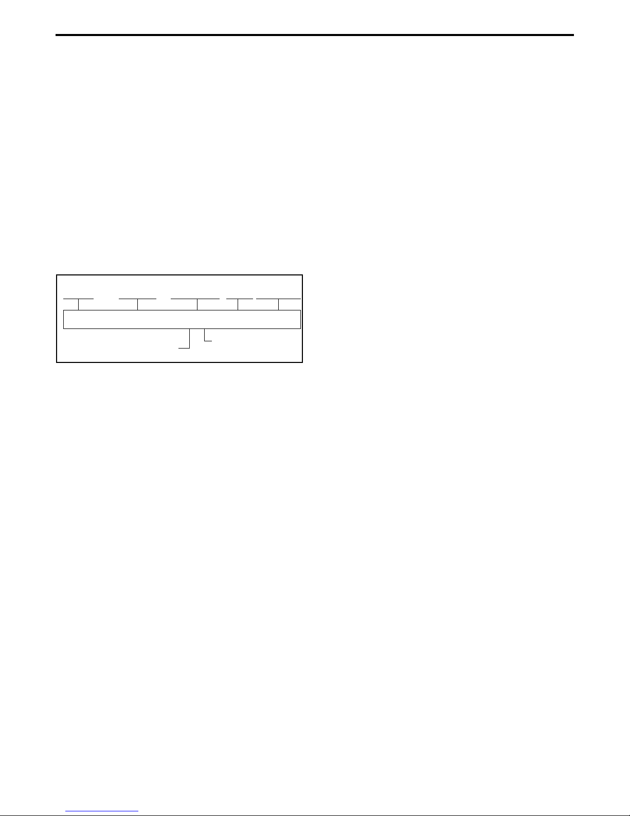
1.5 TRANSCEIVER IDENTIFICATION
The transceiver identification number is printed
on a label that is attached to the chassis. The following
information is contained in the identification number:
1.6 ACCESSORIES
The accessories available for this transceiver are
listed in Table 1-1.
1.7 FACTORY CUSTOMER SERVICE
The Customer Service Department of the
EFJohnson Company provides customer assistance on
technical problems and the availability of local and
factory repair facilities. Regular Customer Service
hours are 8:00 a.m. - 5:00 p.m. Central Time, Monday-
Friday. A technical support subscription service is
available or support can be purchased on an as-needed
basis. The Customer Service Department can be
reached using the following telephone numbers:
Toll-Free: (800) 328-3911 (all except Multi-Net)
(800) 295-1773 (Multi-Net only)
FAX: (972) 818-0639
E-Mail: [email protected]
You can also e-mail a person directly if you know
their first initial/last name (example:
NOTE: Emergency 24-hour technical support is also
available at the 800 and preceding numbers during off
hours, holidays, and weekends.
When your call is answered at the EFJohnson
Company, you will hear a brief message informing
you of numbers that can be entered to reach various
departments. This number may be entered during or
after the message using a tone-type telephone. If you
wait until the message is finished and an operator will
come on the line to assist you. When you enter some
numbers, another number is requested to further cate-
gorize the type of information you need.
You may also contact the Customer Service
Department by mail. Please include all information
that may be helpful in solving your problem. The
mailing address is as follows:
EFJohnson Company
Customer Service Department
1440 Corporate Drive
Irving, TX 75038-2401
1.8 RETURNS FOR REPAIRS
Repair service is normally available through local
authorized EFJohnson Land Mobile Radio Service
Centers. However, before returning equipment, contact
the Customer Service Repair Depot for the correct
“Ship To” address. It is suggested that you call Tech
Support as they may be able to suggest a solution to
the problem that would make return of the equipment
unnecessary.
Be sure to fill out a Factory Repair Request Form
#271 for each unit to be repaired, whether it is in or
out of warranty. These forms are available free of
charge by calling Customer Service (see Section 1.7)
or by requesting them when you send a unit in for
repair. Clearly describe the difficulty experienced in
the space provided and also note any prior physical
damage to the equipment. Include this form in the
shipping container with each unit. Your telephone
number and contact name are important as there are
times when the technicians may have specific ques-
tions that need to be answered in order to completely
identify and repair a problem.
51xx 0 A 12 4 A 12345
Model Revision
Letter Manufacture
Date Warranty
Number
Week No.
of Year Last Digit of Year
PlantFrom P.N.

GENERAL INFORMATION
1-5
Table 1-1 Accessories
Accessory Part No.
Batteries
3600 mAH NiMH standard 587-5100-360
3600 mAH NiMH std intrin safe 587-5100-361*
Battery case for AA alkaline 250-5100-280
Battery eliminator, 12V cigar. lighter plug 585-5100-270
Battery Chargers Kits
Charger kit, -210 chgr, -230 PS, US cord 250-5100-210
Charger kit, -215 chgr, -230 PS, US cord 250-5100-215
Charger kit, -210 chgr, -230 PS, Eur cord 250-5100-220
Charger kit, -215 chgr, -230 PS, Eur cord 250-5100-225
4-unit charger kit, -240 station, four -210
chargers, US cord 250-5100-240
4-unit chgr/cond kit, -240 station, four
-215 charger/conditioners, US cord 250-5100-245
4-unit charger kit as above, Euro cord 250-5100-250
4-unit chgr/cond kit as above, Euro cord 250-5100-255
Vehicular charger 585-5100-260
Battery Charger Replacement Parts
Single-unit rapid chgr, w/o power supply 585-5100-210
Single-unit rapid chgr/cond w/o pwr sup 585-5100-215
Docking station, 4-unit for -210 (-250
power supply included) 585-5100-240
Pwr supply, switching 120/230 VAC, 15V
2.0A, -152 cord required 585-5100-230
Power supply, switching 120/230 VAC
5.0A for docking stat., -152 cord req’d 585-5100-250
Wall mount kit for 4-unit docking station 585-5100-245
Power cord, AC 7-1/2 ft US 597-1001-152
Power cord, AC 6-1/2 ft Euro 597-1001-153
Antennas
136-174 MHz helical wideband (red core) 501-0017-100
136-151 MHz helical (yellow core) 501-0017-101
151-166 MHz helical (black core) 501-0017-103
166-174 MHz helical (blue core) 501-0017-105
403-520 MHz whip dipole 501-0017-107
800 MHz half-wave (red core) 501-0105-013
800 MHz 1/4-wave (white core) 501-0105-012
Carrying Accessories
Leather case with belt flap 585-5100-120
Leather case with belt flap (for use with
alkaline battery clamshell) 585-5100-121
Leather case w/-132 D-swivel belt loop 585-5100-122
2.5” D-swivel belt loop only 585-5100-130
3.0” D-swivel belt loop only 585-5100-132
Radio D-swiv button for -130/-132 loops 585-5100-127
Nylon case with D-swivel belt loop, blk 585-5100-125
Nylon case with D-swivel belt loop, yel 585-5100-126
Belt clip, 2-1/2” std spring loaded 585-5100-128
Belt clip, 3-1/4” long spring loaded 585-5100-129
Speaker/Microphones and Earphones
Spkr/mic, coil cord w/2.5mm earphone jk 589-0015-057*
Replacement coil cord for above spkr/mic 597-2002-101
Earphone kit, coil cord w/2.5mm rt angle
plug, for -057 spkr/mic 589-5100-057*
Spkr/mic, public safety, 800 MHz only,
501-0105-012 antenna req’d 589-0015-058*
Earphone kit, coil cord w/2.5mm straight
plug, for -057 spkr/mic 589-5100-059*
Earphone adapter, w/3.5 mm thrd jack 589-5100-051*
Lightwght headset w/inline PTT for -051 589-0015-059*
1-wire earphone kit, for -051 adapter 589-5100-053*
2-wire palm mic kit, for -051 adapter 589-5100-055*
Programming Accessories
5100 Programming Kit (-488 software,
-920 cable, CD manual) 250-5100-003
5100 Programming Cable 023-5100-920
5100 Cloning Cable 023-5100-930
PCConfigure programming software, CD 023-9998-488
Adapter, DB9M-DB25F 515-9000-015
Test Cables and Accessories
PCTune radio tuning software 023-9998-499
PCTune cable w/2.5mm audio out jack 023-5100-940
Patch cord, 2.5 mm phone plug to BNC 023-5100-950
5100 Tuning Kit (-499 software, -940
cable, -950 patch cord) 250-5100-005
SMA F to BNC F adapter 515-3102-050
UI to Logic Board Test Cable 023-5100-955
Encryption Keyloader Accessories
SMA (PDA) keyloader 250-5000-945
SMA keyloader to 5100 radio cable 023-5000-940
SMA keyloader to 5300 radio cable 023-5000-950
KVL 3000 keyloader to 5100 radio cable 585-5000-932
Table 1-1 Accessories (Continued)
Accessory Part No.
* Accessory is approved for use with intrinsically safe radios.

GENERAL INFORMATION
1-6
When returning equipment for repair, it is also
recommended that you use a PO number or some other
reference number on your paperwork in case you need
to call the repair lab about your unit. These numbers
are referenced on the repair order and make it easier
and faster to locate your unit in the lab.
Return Authorization (RA) numbers are not
necessary unless you have been given one by the Field
Service Department. RA numbers are required for
exchange units or if the Field Service Department
wants to be aware of a specific problem. If you have
been given an RA number, reference this number on
the Factory Repair Request Form sent with the unit.
The repair lab will then contact the Field Service
Department when the unit arrives. For additional
information on factory service, the Depot Service
Department can be contacted at the following E-mail
address:
1.9 REPLACEMENT PARTS
Replacement parts can be ordered directly from
the Service Parts Department. To order parts by phone,
dial the toll-free number as described in Section 1.7.
When ordering, please supply the part number and
quantity of each part ordered. EFJohnson dealers also
need to give their account number. If there is uncer-
tainty about the part number, include the designator
(C512, for example) and the model number of the
equipment the part is from.
You may also send your order by mail or FAX.
The mailing address is as follows and the FAX number
is shown in Section 1.7.
EFJohnson Company
Service Parts Department
1440 Corporate Drive
Irving, TX 75038-2401
1.10 INTERNET HOME PAGE
The EFJohnson Company has an web site that
can be accessed for information on the company about
such things as products, systems, and regulations. The
address is http://www.efjohnson.com.
1.11 INTRINSICALLY SAFE INFORMATION
1.11.1 INTRODUCTION
Intrinsically safe 5100 transceivers have been
approved by the Factory Mutual Research Corporation
for operation in certain flammable atmospheres. The
specific atmospheres in which operation is approved
are shown in Section 1.11.5 and also on the label on
the back cover of the transceiver.
WARNING
When servicing an intrinsically safe transceiver, these
rules must be followed to maintain intrinsic safety:
•Service can be provided only by the factory or by
service centers specifically authorized by the
Factory Mutual Research Corporation to service
EFJohnson intrinsically safe transceivers. Contact
Factory Mutual at the following address for infor-
mationconcerningtheirauditingprocedure.Contact
the EFJohnson Customer Service Department as
described in Section 1.7 if you have questions.
Factory Mutual Research Corporation
1151 Boston-Providence Turnpike
P.O. Box 9102
Norwood, Massachusetts 02062
Phone: (617) 762-4300
•Replacethebattery pack only withIntrinsicallySafe
Battery Pack, Part No. 587-5100-361.
•Do not make any modifications to the circuitry.
•When replacing a part, use only the exact replace-
ment part listed in the service manual parts list.
•Do not install any accessory that is not specifically
approved for use with intrinsically safe 5100
models. Approved accessories are indicated by an
asterisk (*) in Table 1-1.
1.11.2 DEFINITIONS
Intrinsically Safe - This is a fire rating given to these
transceivers by the Factory Mutual Research Corpora-
tion. When electrical equipment is given this rating, the
equipment is considered incapable of releasing suffi-

GENERAL INFORMATION
1-7
cient electrical and thermal energy under normal oper-
ation or specified fault conditions per the testing
standard to cause ignition of a specific flammable or
combustible atmosphere in its most easily ignited con-
centration. In other words, this transceiver should not
cause a fire or explosion when used in certain flamma-
ble atmospheres.
Fault - A defect or electrical breakdown of any compo-
nent, spacing, or insulation which alone or in combina-
tionwith other faults mayadversely affectthe electrical
orthermalcharacteristicsofthe intrinsically safe circuit
(for example, a shorted transistor).
1.11.3 POSSIBLE IGNITION SOURCES
When a transceiver is evaluated by Factory
Mutual, possible sources of ignition are checked.
These sources may be electrical (spark) or thermal
(heat). The following could be sources of spark
ignition:
•Discharge of a capacitive circuit by a fault such as a
short circuit.
•Interruption of an inductive circuit.
•Intermittent making or breaking of a resistive
circuit.
•Hot-wire fusing.
The following could be sources of thermal
ignition:
•Heating of a small-gauge wire or PC board trace.
•High surface temperature of components.
1.11.4 INTRINSICALLY SAFE AND
NONINCENDIVE RATINGS
This transceiver is rated intrinsically safe for
some types of hazards and nonincendive for other
types of hazards. An intrinsically safe rating applies to
operation in Division 1 areas, and a nonincendive
rating applies to operation in Division 2 areas (see
next section). The difference between these ratings is
as follows:
The intrinsically safe rating is a higher rating
because more severe conditions must be met. To be
approved for this rating, the transceiver must not cause
ignition of a particular atmosphere if two of the faults
specified in the testing procedure occur. In other
words, it must be able to withstand two simultaneous
unrelated breakdowns without causing ignition. To
receive a nonincendive rating, the transceiver needs to
withstand only a single fault without causing ignition
of a particular atmosphere.
1.11.5 CLASSIFICATION OF HAZARDOUS
AREAS AND ATMOSPHERES
Introduction
This transceiver has been submitted for approval
to operate in the following hazardous atmospheres and
areas. Contact your sales representative or refer to the
label on the back of the transceiver to determine the
specific atmospheres and areas for which approval was
obtained.
Intrinsically Safe - Class I, II, and III, Division 1,
Groups C, D, E, F, and G. NOTE: Models with the UCM
module (P.N. 242-51xx-xxx-xx3) are not approved for
Group C operation (see Section 1.12).
Nonincendive - Class I, Division 2, Groups A, B, C,
and D.
Temperature Code - T3C
The meanings of these Class, Division, and
Group designations are as follows.
Classification of Hazardous Areas (Division)
Hazardous areas are classified as Division 1 or 2
as shown in Table 1-2. Since a Division 1 area is con-
sidered most hazardous, a transceiver approved for a
specific Division 1 atmosphere can also be used in the
same Division 2 atmosphere. The intrinsically safe rat-
ing applies to Division 1 areas and the nonincendive
rating applies to Division 2 areas.
Atmosphere Classification (Class/Group)
For the purposes of testing and approval, various
atmospheric mixtures have been grouped on the basis
of their hazardous characteristics. Equipment is
approved for a class of material and also for the spe-
cific group of gas, vapor, or dust in that class. Class I
materials include gases and vapors, Class II materials

GENERAL INFORMATION
1-8
include combustible dusts, and Class III materials
include ignitable fibers or flyings. The typical hazard-
ous materials in each group and class are shown in
Table 1-3.
1.12 SECURE COMMUNICATION
NOTE: Refer to Section 11 of the 5100 Operating
Manual for more information on secure communica-
tion. A link to the operating manual is located in
Section 3 of this manual.
General
SecureNet™ and AES voice encryption can be
used to provide secure communication with this trans-
ceiver. These protocols digitize the voice and then
encrypt it using the DES or AES algorithm and an
encryption key. The following types of encryption are
available on analog and digital channels:
Analog Conventional and SMARTNET/Smart-
Zone Analog Channels
•DES
•DES-XL (5100 versions with UCM module
only; see Table 1-4)
Digital Project 25 and SMARTNET/SmartZone
Channels
•DES-OFB (Output Feedback)
•AES (Advanced Encryption Standard). Later
5100 models only. Refer to Section 11 of the
5100OperatingManualformore information (a
link is located in Section 3).
FIPS 140-2 Approved Encryption
DES-OFB and AES encryption is FIPS 140-2
approved in 5100 models equipped with the SEM or
UCM encryption module (see Table 1-4). DES encryp-
tion with the SEM on analog channels and DES-XL
encryption with the UCM is not FIPS approved.
Over-The-Air-Rekeying (OTAR)
Encryption keys are loaded into the radio by
OTAR (Over-The-Air-Rekeying) using a KMF (Key
Management Facility) and/or a handheld keyloader
such as the EFJohnson SMA (Subscriber Manage-
ment Assistant) or Motorola KVL 3000 Plus with the
AES option.
The keyloader is connected directly to the radio
using an interconnect cable, and it loads DES, DES-
OFB, and AES keys. Currently, OTAR can be used to
load DES-OFB keys on Project 25 conventional chan-
nels. Future OTAR of AES keys and on Project 25
trunked channels is planned. Refer to Section 8 of the
5100 Operating Manual for more OTAR information.
A link to this manual is located in Section 3 of this
manual.
Table 1-2 Area Classification
Division Area
Class I and II Materials (Gases, Vapors, and Dusts)
1 An area where there is or could be an explosive
atmosphere most of the time in normal
operation
2 An area where an explosive atmosphere exists
only as a result of a fault (something going
wrong)
Class III Materials (Fibers or Flyings)
1 An area in which easily ignitable fibers or mate-
rials producing combustible flyings are handled,
manufactured, or used.
2 An area in which easily ignitable fibers are
stored or handled. An exception is in process of
manufacture.
Table 1-3 Material Classification
Typical Hazard Group Class
Acetylene A I
Hydrogen B I
Ethylene, ethyl ether, cyclopropane C I
Gasoline, naphtha, butane, propane,
alcohol, acetone, benzol, natural gas DI
Metal dust including aluminum, mag-
nesium, and their alloys EII
Carbon black, coal, or coke dust F II
Flour, starch, or grain dusts G II
Ignitable fibers/flyings such as rayon
or cotton -III

GENERAL INFORMATION
1-9
Figure 1-1 Hardware Changes Flowchart
AnoisreV
)ylnO
n
oitpyrcnEe
ra
wtfoS
(
d
r
aoB
c
igo
L
011
-0015-
3
20
draoBIU
014
-0015-
3
20
y
lnO
no
itpyrcnEerawtfo
S
elba
l
i
a
vaton
LX-S
ED
devorpp
a
SPIF
toN
e
ra
w
m
r
iF
x.x.1
no
i
s
r
eV
draoBci
g
oLMES
051-0015-
3
20
d
ra
oB
IU
MES
054
-001
5-
32
0
dra
o
BcigoLMCU
061-001
5
-320
d
ra
oB
IUM
CU
064
-0015-
3
2
0
BnoisreV
M
n
o
i
t
p
yrcnE
e
ta
rapeS( )
elu
do
elbal
i
avaton
L
X-
S
ED
d
e
v
o
rp
pa
S
P
IF
e
rawm
r
iF
x.
x.
2
n
o
i
sr
eV
noisreVhtiwelbitapmoC
ylnOseludoMFRBdna
A
elbaliavaLX
-S
E
D
devorppa
SPI
F
erawmriFx.x.3noisreV
noisreVhtiwelbitapmoC
y
l
n
Ose
lu
d
o
MFR
B
d
n
a
A
draoBcigoLMES
021-0055-320
dra
oBIU
MES
024-
005
5
-3
2
0
elbaliavat
o
nLX-
S
ED
devorpp
a
SPIF
erawmriFx.x.4noisreV
noisreVhtiwelbitapmoC
ylnOseludoMFRC
no
i
t
c
udo
rP
0015
300
2
t
r
atS 5002
yBdecalpeR
deu
n
itnocs
i
D
deunitnocs
iD
SEGNAHCCIGOL
AnoisreV
F
HV
100
-011
5-
32
0
zH
M
083
F
HU
100
-021
5-3
2
0
zH
M
0
54
FHU
100
-041
5-320
zH
M
304
FH
U
100
-031
5-3
2
0
zHM
008
100-081
5
-320
z
HM
471-431
zH
M
074-0
83
zHM
0
74
-
304
zHM215-054
zHM078-608
BnoisreV
FH
V
100-01
15-3
20
zHM083FHU
1
00
-021
5-
32
0
zHM
0
54
FHU
1
00
-041
5-
3
20
zHM
304FH
U
1
00
-031
5-
32
0
zHM
0
08
100-08
1
5-320
zHM471-431
zH
M
07
4
-0
8
3
zHM074-304
zHM215-054
zHM078-608
ehthtiW.segnahcr
e
htodn
a
dnet
n
orf
x
r
ro
n
im
evahselud
o
mese
h
T
r
o
01
.1
.
1no
i
sre
VenuTC
P,)ret
a
l
ro"B"
retteLveR
(
ylno
e
ludom
FHV
.desuebnac9.8.0.1noisr
e
V,srehtoe
h
thtiW.desuebtsumretal
otdesueb
nac
9.8.
0
.1enu
T
CP
.s
e
l
u
domesehtenut
CnoisreV
FHV
001-0055-585
zHM083FHU
003-005
5
-
5
85
zH
M054FHU
0
05-005
5
-
5
85
zHM304FHU
003-0055-585
z
H
M
008-0
0
7
007-0055-585
zHM471-431
zHM074-083
zHM074-304
zHM215-054
zHM
0
7
8-
2
6
7
y
Bde
ca
lpeR
yBdecalpeR
y
Bdec
al
p
eR
y
B
decalpeR
yBdecalpeR
yBdecalpeR
yBdecalpeR
yBdecalpeR
y
B
decalpeR
yBdecalpeR
eratahtseludomden
g
isederylete
l
p
m
oC
.
y
lnoc
i
g
o
L
Cno
i
sreVh
t
iwe
l
bitapmo
c
.
de
s
ue
b
ts
u
mre
t
a
lro
0
.
2n
o
i
sr
e
Ve
nu
T
C
P
SEGNAHCELUDOMFR
40
0
2
CnoisreV
M
noi
t
p
y
r
cnE
e
t
ara
peS
()
el
u
d
o
1.13 RADIO HARDWARE CHANGES
NOTE: Version A/B/C references in the following
information are for descriptive purposes in this
manual only and do not correspond to any radio revi-
sion letters or letters on the boards.
1.13.1 RF MODULE CHANGES
As shown in Figure 1-1, there have been three
significant changes to the RF module used in 5100
series radios:
Version A - This is the original module version that
was used until approximately late 2003. All versions
of PCTune can be used to tune radios with these
modules. The schematic diagrams and board layout for
this VHF board are located in the Unrev_Bd folder
and the other boards are located in Section 8.
Version B - The changeover to this version occurred
starting in late 2003. This change was made because of
part obsolescence. Significant changes occurred to
only the VHF board, so this is the only board with
revised schematics and layouts in this manual. With
the UHF and 800 MHz boards, only minor layout and
value changes occurred. The Version B boards are
being replaced by the following Version C boards as
they become available.
NOTE: PCTune, Version 1.10.0 or later must be used
to tune VHF radios with this board (see following).
PCTune Version 1.10.0 or later must be used to
adjust radios with the Version B VHF board because
of changes made in the front end. The earlier version
(1.0.8.9) can still be used to tune all other Version B
and all Version A boards.

GENERAL INFORMATION
1-10
The Revision Letter in the radio identification
number (see Section 1.5) can be used to determine if a
VHF radio has this new Version B board. Radios with
a Revision Letter of “B” or later have the new board
and PCTune 1.10.0 or later must be used.
Version C - These boards are a completely new
design. Highlights of this board version are as follows:
•Becauseofdifferentinterfacerequirements,thenew
Version C logic and UI boards described in the next
section must be used. This logic is PowerPC-based,
similar to Version A and B.
•A new version of the PCTune software (2.0 or later)
is required to tune radios with these boards.
•The new 800 MHz version of this board operates on
both 700 and 800 MHz channels instead of only 800
MHz channels like the A and B versions. Therefore,
radios with the Version C board can operate on
channels from 762-870 MHz, while radios with the
earlier Version A and B boards can operate only on
channels from 806-870 MHz.
Radios with this new 700/800 MHz RF board have
a “7” as the “F” character of the radio part number
(see Section 1.4), while radios with the older A and
B versions have an “8” for this character.
1.13.2 LOGIC AND UI BOARD CHANGES
As shown in Figure 1-1 and Table 1-4, there have
been three significant changes to the control logic used
in 51xx series radios. More information on these
changes follows.
NOTE: The firmware version number (1.x/2.x/3.x) is
briefly displayed when radio power is turned on.
Version A - This version of logic and UI boards
provides software generated encryption (Version 1 in
Table 1-4). DES-XL and FIPS 140-2 approval is not
available with these models.
Version B - This version began shipping in mid 2003
to provide FIPS 140-2 approved and DES-XL encryp-
tion. SEM and UCM versions of these boards are
available (Versions 2 and 3 in Table 1-4). These boards
have separate encryption modules to provide encryp-
tion instead of doing it through software. The SEM
and UCM versions are functionally the same except
only the UCM version provides DES-XL encryption.
Normally, the SEM version is used unless DES-XL
encryption is required.
Version C - This version of the logic and UI boards is
a new design that is required to interface with the new
Version C RF module. Only a SEM version will be
offered (similar to Version 2 in Table 1-4). This
version of boards has more Flash and RAM memory
to allow additional features to be added if necessary.
This logic version uses Version 4.x.x firmware.

GENERAL INFORMATION
1-11
Table 1-4 51xx Family Logic and Firmware Versions
Logic/Radio Version [1] Application
(Firmware)
Code Base
Analog Channel
Encryption Digital Channel
Encryption
DES DES-XL DES-OFB AES
Version 1 (No Module/Software Encryption)
Current standard version which uses the -110 Logic
board and -410 UI Board. Not FIPS approved.
1.xx Yes No Yes Yes
Version 2 (uses EFJ SEM module)
Current version which has the EFJohnson SEM
(Subscriber Encryption Module) on the logic board.
This version uses the -150 Logic and -450 UI
boards. All radios include the SEM, and the desired
encryption options (if any) are enabled by factory
programming. FIPS approved.
2.xx Yes No Yes Yes
Version 3 (uses Motorola UCM module)
Current version which has the Motorola UCM
(Universal Crypto Module) on the logic board. This
version uses the -160 Logic and -460 UI boards, and
is ordered when DES-XL encryption is required.
FIPS approved.
3.xx Yes Yes Yes Yes
Version 4 (uses EFJ SEM module)
New version designed for use with the new Version
C RF modules described in Section 1.13.1. It uses
the same EFJohnson SEM (Subscriber Encryption
Module) as Version 2 boards above. This version
uses 5500-120 Logic and 5500-420 UI boards. All
radios include the SEM, and the desired encryption
options (if any) are enabled by factory program-
ming. FIPS approved.
4.xx Yes No Yes Yes
[1] The version number of Versions 1-3 is also indicated by the 13th digit of the radio part number (242-51xx-xxx-xxV).

GENERAL INFORMATION
1-12
5100 PORTABLE SPECIFICATIONS
The following are general specifications intended for use in testing and servicing this transceiver. For current
advertised specifications, refer to the specification sheet available from your sales representative. Values are
typical and are subject to change without notice.
GENERAL
Frequency Range VHF: 136-174 MHz
UHF: 380-470 MHz, 403-470 MHz, 450-512 MHz
700/800 MHz: 762-870 MHz, 800 MHz: 806-870 MHz (see Section 1.2.2)
Available Operating Modes Conventional analog, Project 25 conv. and trunked, SMARTNET/SmartZone
analog and digital (see Section 1.2.4)
Channels/Talk Groups Up to 512 (dependent on available memory)
Transmit/Receive Separation Any frequency within the range
Channel Spacing VHF: 12.5, 25, and 30 kHz
UHF: 12.5 and 25 kHz
700/800 MHz: 12.5 and 25 kHz
Maximum Deviation 25 kHz analog - 5 kHz
12.5 kHz analog - 2.5 kHz
12.5 kHz analog NPSPAC - 4.0 kHz
Frequency Stability VHF/UHF - 2.0 PPM, 700/800 MHz - 1.5 PPM (–22 to +140° F or –30 to
+60° C)
Dimensions (w/o antenna) 6.7” H x 2.52” W x 1.9” D (17.0 cm x 6.4 cm x 4.8 cm)
Weight (w/std battery) 24 oz. (675 g)
Supply Voltage 7.2 volts DC nominal
Battery Life 13 hours typical w/std 3600 mAH battery
Current Drain (maximum Standby - 200/210 mA (with Ver A B/Ver C RF board, see Section 1.13.1)
w/o backlight, w/backlight Receive (rated audio out) - 400/430 mA
add 100 mA) Low Tx Power - 1.5/1.3 A
High Tx Power - 2.8/2.4 A
RECEIVER
Sensitivity 0.25 µV (analog mode 12 dB SINAD), 0.25 µV (digital mode 5% BER)
Selectivity –75 dB
Spurious and Image Rejection –75 dB (VHF/UHF), –80 dB (700/800 MHz)
Intermodulation –78 dB (VHF), –77 dB (UHF), –75 dB (700/800 MHz)
Maximum Frequency Spread Any spread within the range
Audio Power Output 500 mW
Audio Distortion Less than 2% at 1 kHz
TRANSMITTER
RF Power Output VHF: 5W (high), 1W (low)
UHF: 4W (high), 1W (low)
700 MHz: 2.5W (high/TA), 1W (low)
800 MHz: 3W (high), 1W (low), 2.5 TA
Spurious and Harmonic Emissions –70 dB (VHF/UHF), –75 dB (700/800 MHz)
FM Hum and Noise –45 dB at 25 kHz bandwidth
Audio Modulation 16K0F3E, 8K10F1E (all), 11K0F3E (VHF/UHF), 14K0F3E (700/800 MHz)
Audio Distortion Less than 2% at 1 kHz
Maximum Frequency Spread Any spread within the band

2-1
BATTERY, ACCESSORY, AND DISASSEMBLY INFORMATION
SECTION 2 BATTERY, ACCESSORY, AND DISASSEMBLY INFORMATION
Figure 2-1 Battery Removal
Battery Release
Button
2.1 BATTERY INFORMATION
2.1.1 BATTERY REMOVAL/INSTALLATION
To remove the battery from the radio for
recharging or replacement, press the release button
(see Figure 2-1) and then rotate it upward to the
approximate point shown and remove it from the
radio.
2.1.2 BATTERY CHARGING
NOTE: Do not charge the battery with radio power on
(see following).
The battery can be charged separately or while
attached to the radio. When it is charged while
attached to the radio, radio power should be turned off.
If it is not, the battery begins slowly discharging when
the trickle charge mode is entered. The trickle mode is
indicated by a green Ready indication, and it is entered
automatically when the battery is nearly fully charged.
Gradual discharging occurs in the trickle mode
because the charge current of approximately 50 mA is
less than the radio standby current of 200 mA.
CAUTION: Do not transmit in close proximity to the
charger base (see following).
Do not expose the charger base to high level RF
signals while a battery is being charged because this
may cause a charger fuse to blow (especially in the
UHF range). Radios programmed for SMARTNET/
SmartZone operation, for example, may affiliate while
in the charger which causes them to key automatically.
Therefore, do not leave radio power on while charging
as described above.
2.1.3 PREVENTING LOSS OF ENCRYPTION
KEYS
NOTE: Later models (manufactured in 2003 and later)
have reduced storage time as follows.
If Infinite Key Retention is not programmed, the
transceiver must be connected to a constant power
source to preserve the encryption keys in memory.
Storage capacitors maintain the supply voltage (and
these keys) for approximately 30 seconds to allow the
battery to be changed. Therefore, when changing the
battery of a transceiver containing keys, make sure to
reattach another battery within 30 seconds.
Models with Flash code 1.11.0 or later can be
programmed for Infinite Key Retention. The keys are
then stored in memory and are not lost, even if power
is disconnected for an extended period.
BATTERY, ACCESSORY, AND DISASSEMBLY INFORMATION
2-2
2.1.4 BATTERY CARE
WARNING: Do not incinerate a battery pack because
it may explode. Also, do not short circuit the terminals
because the battery pack and the object causing the
short may become very hot. Do not disassemble or
modify a battery pack.
Proper battery care enhances the useful life of the
battery. The battery should be recharged as soon a
practical after the low battery indication appears (see
Section 3). Follow the charging instructions in the
manual included with the charger. When the battery
fails to hold a charge or provides only a very short
operating time, it must be replaced with a new unit.
A fully charged battery provides approximately
13 hours of service before recharging is required. This
time assumes that 5% of the time is spent transmitting,
5% in the receive unsquelched mode, and 90% in the
receive squelched mode. The operating time may be
less if more time is spent in the transmit or
unsquelched modes, or if the battery is not fully
charged or its capacity has deteriorated. Be sure to
dispose of the nickel metal-hydride (NiMH) battery
pack in accordance with local waste regulations.
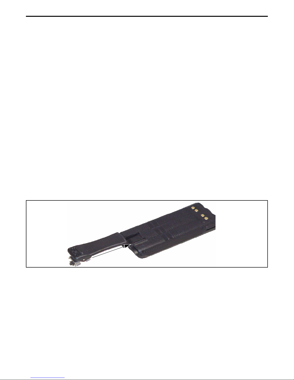
Figure 2-2 Belt Clip Installation
2.2 BELT CLIP INSTALLATION
Remove the battery and slide the belt clip into the
slot on the battery as shown in Figure 2-2. To remove
the clip, simply slide it out. It is held in place by the
chassis when the battery is installed on the radio.

BATTERY, ACCESSORY, AND DISASSEMBLY INFORMATION
2-3
Figure 2-3 Accessory Installation
Latch
Install Lock
Screw Here
Accessory Connector
Hook
2.3 ACCESSORY INSTALLATION
To connect an accessory such as a speaker-
microphone to the transceiver, refer to Figure 2-3 and
proceed as follows:
1. Remove the dust cover over the accessory jack on
the side of the transceiver.
2. Insert the hook of the accessory connector into the
slot on the side of the transceiver.
3. Hold the latch open, press the connector against the
transceiver, and then release the latch to lock the
connector in place.
4. Install the included locking screw in the latch tab in
the location shown.
Option Select Lines
Opt Sel 1 (pin 1) and Opt Sel 2 (pin 5) of the
UDC (accessory) connector indicate to the control
logic when an accessory is connected and what acces-
sory is installed. These lines function as follows:
Opt Sel 1 and 2 High (3.3V) - This is the normal
operating condition in which no accessory is
connected. Both lines are pulled high (3.3V) by
internal pull-up resistors.
Opt Sel 1 Low - A speaker-microphone or some other
accessory is connected. Opt Sel 2 then functions as an
external PTT line (low = PTT), and the radio PTT
switch is also functional. The internal speaker and
microphone are disabled.
Opt Sel 1 High, Opt Sel 2 Low - The encryption
keyloader is connected.
Other manuals for 5100 Series
3
Table of contents
Other E.F. Johnson Company Portable Radio manuals

E.F. Johnson Company
E.F. Johnson Company 7243 LTR-NET User manual

E.F. Johnson Company
E.F. Johnson Company 5100 ES User manual

E.F. Johnson Company
E.F. Johnson Company 5100 Series Reference guide

E.F. Johnson Company
E.F. Johnson Company 002-8170-001 User manual

E.F. Johnson Company
E.F. Johnson Company 5100 ES User manual

E.F. Johnson Company
E.F. Johnson Company 5100 Series User manual

E.F. Johnson Company
E.F. Johnson Company MULTI-NET II User manual

E.F. Johnson Company
E.F. Johnson Company 8500 Series User manual

E.F. Johnson Company
E.F. Johnson Company 51 Series User manual

E.F. Johnson Company
E.F. Johnson Company 4100 SERIES User manual


