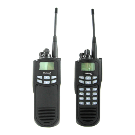
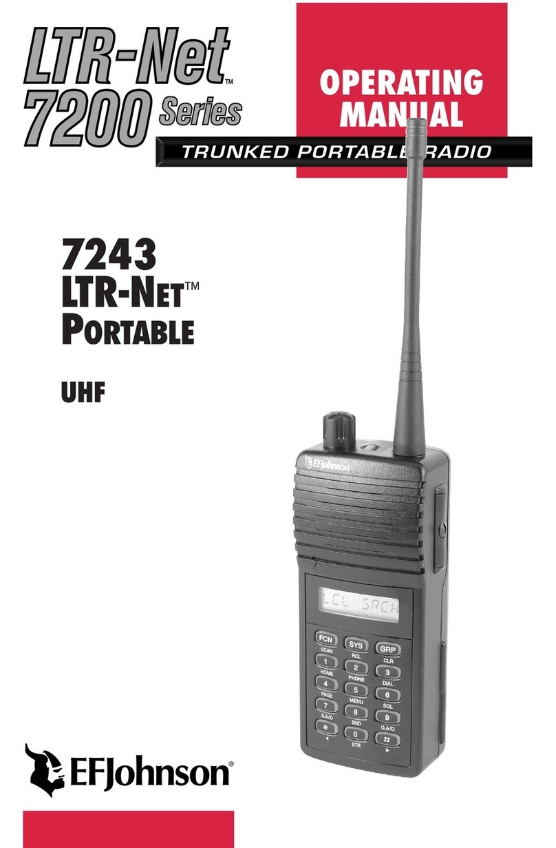
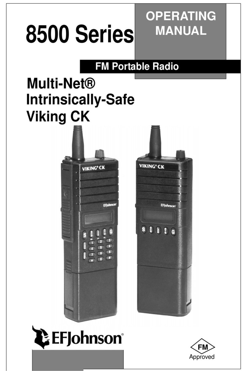
E.F. Johnson Company 51 Series User manual

1
51xx Series
FM Portable Radio
Project 25, Conventional
SMARTNET
™
, SmartZone
®
PRELIMINARY
OPERATING
MANUAL


LAND MOBILE PRODUCT WARRANTY - The manufacturer’s
warranty statement for this product is available from your product
supplier or from the E.F. Johnson Company, 299 Johnson Avenue, Box
1249, Waseca, MN 56093-0514. Phone (507) 835-6222.
Copyright© 2001 by the E.F. Johnson Company
E.F. Johnson Company, which was founded in 1923, designs, manufac-
tures, and markets radio communication products, systems, and services
worldwide. E.F. Johnson produces equipment for land mobile radio and
mobiletelephone services which include business, industrial, government,
public safety, and personal users.
Viking Head/EFJohnson logo and Call Guard® are trademarks of the E.F.
Johnson Company. SMARTNET™, SmartZone®, Call Alert™, Enhanced
Private Conversation™, and Private Conversation II™ are trademarks of
Motorola, Inc. All other company and/or product names used in this manual are
trademarks and/or registered trademarks of their respective manufacturer. The
IMBE™ voice coding technology embodied in this product is protected by
intellectual property rights including patent rights of Digital Voice Systems, Inc.

SAFETY TRAINING INFORMATION
4
SAFETY TRAINING INFORMATION
WARNING
This radio produces RF electromagnetic energy when transmitting and is
designed and classified for “Occupational Use Only”. Radio equipment
with this classification must be used only during the course of employ-
ment by individuals aware of the hazards and the ways to minimize such
hazards. This radio is NOT intended for use by the General Population in
an uncontrolled environment.
This radio has been tested and complies with FCC RF exposure limits for
“Occupational Use Only”. In addition, it complies with the following
standards and guidelines with regard to RF energy and electromagnetic
energy levels and evaluation of such levels for exposure to humans:
•FCC OET Bulletin 65 Edition 01-01 Supplement C, Evaluating
Compliance with FCC Guidelines for Human Exposure to Radio
Frequency Electromagnetic Fields.
•AmericanNationalStandardsInstitute(C95.1-1992),IEEE Standard
for Safety Levels with Respect to Human Exposure to Radio
Frequency Electromagnetic Fields, 3 kHz to 300 GHz.
•American National Standards Institute (C95.3 -1992), IEEE Recom-
mended Practice for the Measurement of Potentially Hazardous
Electromagnetic Fields - RF and Microwave.
CAUTION
To ensure that your exposure to RF electromagnetic energy is within the FCC
allowable limits for occupational use, always adhere to the following guidelines:
•DO NOT operate the radio without the proper antenna attached. This may
damage the radio and cause FCC RF exposure limits to be exceeded. The
proper antenna is the antenna supplied with the radio by the manufacturer
or an antenna specifically authorized by the manufacturer for use with this
radio.

SAFETY TRAINING INFORMATION
5
•DO NOT transmit more than 50% of total radio use time (50% duty cycle).
Transmitting for more than 50% of the time can cause FCC RF exposure
compliance requirements to be exceeded. This radio is transmitting when-
ever Tx is indicated in the display. Pressing the PTT switch on the side
usually causes the radio to transmit.
•DO NOT use any accessories not specifically authorized by the E.F.
Johnson Company for use with this radio such as batteries, speaker-
microphones, belt clips, and antennas. The use of unauthorized accessories
can cause FCC RF exposure compliance requirements to be exceeded.
•ALWAYS keep the antenna and radio at least 2.54 cm (1.0 inch) away from
your body when transmitting to ensure FCC RF exposure compliance
requirements are not exceeded. The best transmission quality results when
the antenna is at least 5 cm (2 inches) away from your mouth and angled
slightly to one side.
NOTE: The preceding information is provided to make you aware of RF
exposure and what to do to ensure that this radio is operated within FCC RF
exposure limits.
Electromagnetic Interference/Usage Compatibility
This device complies with Part 15 of the FCC rules. Operation is subject to the
condition that this device does not cause harmful interference. In addition,
changes or modification to this equipment no expressly approved by the E.F.
Johnson Company could void the user’s authority to operate this equipment
(FCC Rules, 47CFR Part 15.19).
DO NOT operate it in areas that are sensitive to RF energy such as aircraft,
hospitals, blasting sites, and fuel storage sites. Areas with potentially flammable
atmospheres are usually, but not always, clearly posted. These may include gas
stations, fuel and chemical storage and transfer stations, below deck on boats,
and areas where the air contains flammable chemicals or particles such as grain
dust or metal powders.
Dispose of the nickel metal-hydride battery used by this radio in accordance with
local regulations. DO NOT dispose of it in fire because it can explode. Also, do
not short the terminals because it may become very hot.
FEATURES
6
FEATURES
General Features
•Programmable for the following modes of operation:
– Conventional analog
– Conventional Project 25 (digital)
– SMARTNET™/SmartZone® trunked (analog or digital)
•Up to 16 zones with up to 16 channels each programmable
(256 channels total)
•Large liquid crystal display (LCD) with backlight
•Nine programmable option switches (full keypad model)
•Standard and radio-wide scan modes
•Time-out timer
•Power-up password access available to prevent unauthorized usage
Conventional Features
•Up to 256 channels or talk groups programmable
•Repeater talk-around
•Monitor mode selected by option switch
•Carrier or Call Guard®controlled squelch on analog channels
•Penalty and conversation timers
•Priority channel sampling when scanning
•Busy channel lockout (transmit disable on busy)
•SecureNet™or 460 secure communication available on analog
channels, DES-OFB on Project 25 channels
•Individual ID calls on Project 25 channels
•User selectable high and low power output
•Emergency switch (P25 channels only)
•Keypad programming

FEATURES
7
SMARTNET™ II/SmartZone® Features
•Up to 256 talk groups programmable
•Group, Enhanced Private Conversation™, Private Conversation II™,
and Telephone Calls
•Emergency alarms to alert dispatcher of emergency conditions
•Emergency calls for high priority system access
•Failsoft operation on a predefined conventional channel if trunked sys-
tem fails
•Priority group calls detected while listening to other group calls
•Call Alert™ (send and receive pages)
•Predefined messages (up to 16) can be sent to a dispatcher
•Predefined status conditions (up to 8) can be sent to a dispatcher
•Dynamic regrouping (dispatcher can automatically gather users on a
channel to receive a message)
•Roaming (SmartZone only)
•SecureNet™ or 460 secure communication available
NOTE: The availability of many of the preceding features is controlled by
system operator programming of your transceiver, installed options, and
the capabilities of the radio system being accessed.

FEATURES
8
NOTES

TABLE OF CONTENTS
9
TABLE OF CONTENTS
SAFETY TRAINING INFORMATION . . . . . . . . . . . . . . . . . . . . . . . . 4
FEATURES . . . . . . . . . . . . . . . . . . . . . . . . . . . . . . . . . . . . . . . . . . . . . . 6
General Features. . . . . . . . . . . . . . . . . . . . . . . . . . . . . . . . . . . . . . . . . 6
Conventional Features . . . . . . . . . . . . . . . . . . . . . . . . . . . . . . . . . . . .6
SMARTNET™ II/SmartZone® Features. . . . . . . . . . . . . . . . . . . . . . 7
OPTION SWITCH FUNCTIONS. . . . . . . . . . . . . . . . . . . . . . . . . . . .11
CONTROLS AND DISPLAY. . . . . . . . . . . . . . . . . . . . . . . . . . . . . . .13
Front Panel Controls. . . . . . . . . . . . . . . . . . . . . . . . . . . . . . . . . . . . .13
Top Panel Controls. . . . . . . . . . . . . . . . . . . . . . . . . . . . . . . . . . . . . .15
Side Controls . . . . . . . . . . . . . . . . . . . . . . . . . . . . . . . . . . . . . . . . . .16
Display . . . . . . . . . . . . . . . . . . . . . . . . . . . . . . . . . . . . . . . . . . . . . . . 17
GENERAL OPERATION. . . . . . . . . . . . . . . . . . . . . . . . . . . . . . . . . .18
Introduction . . . . . . . . . . . . . . . . . . . . . . . . . . . . . . . . . . . . . . . . . . .18
Turning Power On and Setting Volume. . . . . . . . . . . . . . . . . . . . . . 18
Power-Up Password . . . . . . . . . . . . . . . . . . . . . . . . . . . . . . . . . . . . .19
Backlight. . . . . . . . . . . . . . . . . . . . . . . . . . . . . . . . . . . . . . . . . . . . . . 20
Option Switches . . . . . . . . . . . . . . . . . . . . . . . . . . . . . . . . . . . . . . . .20
Keypad Lock . . . . . . . . . . . . . . . . . . . . . . . . . . . . . . . . . . . . . . . . . . 21
Low Battery Indication. . . . . . . . . . . . . . . . . . . . . . . . . . . . . . . . . . . 21
Channel and Zone Selection. . . . . . . . . . . . . . . . . . . . . . . . . . . . . . .21
Home Zone. . . . . . . . . . . . . . . . . . . . . . . . . . . . . . . . . . . . . . . . . . . . 22
Time-Out Timer . . . . . . . . . . . . . . . . . . . . . . . . . . . . . . . . . . . . . . . .22
Tone Enable/Disable . . . . . . . . . . . . . . . . . . . . . . . . . . . . . . . . . . . .23
Scanning. . . . . . . . . . . . . . . . . . . . . . . . . . . . . . . . . . . . . . . . . . . . . .23
Secure Communication . . . . . . . . . . . . . . . . . . . . . . . . . . . . . . . . . .28
Transceiver Operating Modes . . . . . . . . . . . . . . . . . . . . . . . . . . . . .28
CONVENTIONAL FEATURES. . . . . . . . . . . . . . . . . . . . . . . . . . . . . 29
Introduction . . . . . . . . . . . . . . . . . . . . . . . . . . . . . . . . . . . . . . . . . . .29
Display Mode Selection . . . . . . . . . . . . . . . . . . . . . . . . . . . . . . . . . . 30
Monitoring Before Transmitting . . . . . . . . . . . . . . . . . . . . . . . . . . . 30
Monitor Mode. . . . . . . . . . . . . . . . . . . . . . . . . . . . . . . . . . . . . . . . . .31
Busy Channel Lockout . . . . . . . . . . . . . . . . . . . . . . . . . . . . . . . . . . .32
Call Guard Squelch. . . . . . . . . . . . . . . . . . . . . . . . . . . . . . . . . . . . . .32
Penalty Timer . . . . . . . . . . . . . . . . . . . . . . . . . . . . . . . . . . . . . . . . . .33
Conversation Timer . . . . . . . . . . . . . . . . . . . . . . . . . . . . . . . . . . . . . 34
Repeater Talk-Around . . . . . . . . . . . . . . . . . . . . . . . . . . . . . . . . . . .34

TABLE OF CONTENTS
10
Power Output Select. . . . . . . . . . . . . . . . . . . . . . . . . . . . . . . . . . . . . 34
Emergency Mode (Conventional) . . . . . . . . . . . . . . . . . . . . . . . . . . 35
Conventional Mode Scanning . . . . . . . . . . . . . . . . . . . . . . . . . . . . .35
Priority Channel Sampling. . . . . . . . . . . . . . . . . . . . . . . . . . . . . . . . 36
Placing and Receiving Standard Conventional Calls. . . . . . . . . . . .37
DTMF/ANI Signaling . . . . . . . . . . . . . . . . . . . . . . . . . . . . . . . . . . .38
Project 25 Mode Features. . . . . . . . . . . . . . . . . . . . . . . . . . . . . . . . .39
Keypad Programming. . . . . . . . . . . . . . . . . . . . . . . . . . . . . . . . . . . . 40
Channel Parameter Programming. . . . . . . . . . . . . . . . . . . . . . . . . . . 43
SMARTNET/SMARTZONE FEATURES . . . . . . . . . . . . . . . . . . . .46
Introduction . . . . . . . . . . . . . . . . . . . . . . . . . . . . . . . . . . . . . . . . . . .46
Viewing Unit ID. . . . . . . . . . . . . . . . . . . . . . . . . . . . . . . . . . . . . . . .46
Standard Group Calls . . . . . . . . . . . . . . . . . . . . . . . . . . . . . . . . . . . .46
Enhanced Private Conversation Calls . . . . . . . . . . . . . . . . . . . . . . .47
Private Conversation II Calls . . . . . . . . . . . . . . . . . . . . . . . . . . . . . . 51
Telephone Calls . . . . . . . . . . . . . . . . . . . . . . . . . . . . . . . . . . . . . . . .53
Call Alert . . . . . . . . . . . . . . . . . . . . . . . . . . . . . . . . . . . . . . . . . . . . . 56
Messaging. . . . . . . . . . . . . . . . . . . . . . . . . . . . . . . . . . . . . . . . . . . . . 57
Sending Status Conditions . . . . . . . . . . . . . . . . . . . . . . . . . . . . . . . .58
Emergency Alarm and Emergency Call. . . . . . . . . . . . . . . . . . . . . . 58
Failsoft Operation. . . . . . . . . . . . . . . . . . . . . . . . . . . . . . . . . . . . . . .59
SMARTNET/SmartZone Scanning . . . . . . . . . . . . . . . . . . . . . . . . .60
Dynamic Regrouping . . . . . . . . . . . . . . . . . . . . . . . . . . . . . . . . . . . . 60
SmartZone Features . . . . . . . . . . . . . . . . . . . . . . . . . . . . . . . . . . . . . 61
MISCELLANEOUS. . . . . . . . . . . . . . . . . . . . . . . . . . . . . . . . . . . . . . .62
Supervisory Tones . . . . . . . . . . . . . . . . . . . . . . . . . . . . . . . . . . . . . .62
Rechargeable Battery Pack. . . . . . . . . . . . . . . . . . . . . . . . . . . . . . . .64
System Operator Programming . . . . . . . . . . . . . . . . . . . . . . . . . . . . 66
Speaking Into Microphone. . . . . . . . . . . . . . . . . . . . . . . . . . . . . . . .66
Operation At Extended Range . . . . . . . . . . . . . . . . . . . . . . . . . . . . .66
Licensing . . . . . . . . . . . . . . . . . . . . . . . . . . . . . . . . . . . . . . . . . . . . .66
Transceiver Service . . . . . . . . . . . . . . . . . . . . . . . . . . . . . . . . . . . . . 67
INDEX. . . . . . . . . . . . . . . . . . . . . . . . . . . . . . . . . . . . . . . . . . . . . . . . . . 70

OPTION SWITCH FUNCTIONS
11
OPTION SWITCH FUNCTIONS
The programmable option switches are as follows:
•F1, F2, F3, and F4 keys on the front panel
•Three push-button switches on the side
•Orange push-button switch on the top panel
•Three-position A/B/C switch on top panel
These switches can control one function when a conventional
channel is selected and another when a SMARTNET/SmartZone channel
is selected. The available functions for each operating mode and the page
on which each function is described are listed in the following tables.
Consult your system operator to determine what functions are controlled
by each switch and then write the switch label next to the applicable func-
tion. Refer to page 20 for more option switch information.
CONVENTIONAL MODE
Switch Function See Page
Backlight 20
Clear/Secure 28
Displayed Information 30
High/Low Power 34
Home Zone 22
Individual ID Call 40
Keypad Lock 21
Keypad Programming 40
Monitor 31
Normal/Selective 32
Priority 36
Radio Wide Scan 24
Repeater Talk-Around 34
Scan 24
Scan Edit 26
Talk Group Select 39
Tones On-Off 23
Zone Select 21

OPTION SWITCH FUNCTIONS
12
SMARTNET/SMARTZONE MODE
Switch Function See Page
Backlight 20
Call Alert 56
Call Response 50, 52
Clear/Secure 28
Home Zone 22
Keypad Lock 21
Message 57
Phone 53
Private Call 47, 51
Radio Wide Scan 24
Scan 24
Scan Edit 26
Site Lock (SmartZone only) 61
Site Search (SmartZone only) 61
Status 58
Tones On-Off 23
Zone Select 21

CONTROLS AND DISPLAY
13
CONTROLS AND DISPLAY
Front Panel Controls
Speaker - The transceiver speaker is located behind this grill. When a
speaker/microphone is used, this speaker is automatically disabled.
Microphone - The microphone is located in this area. For best results,
hold the transceiver 2-3 inches from you mouth and speak at a normal
conversational level.
Speaker
Display
DTMF Keypad
Option Keys
Microphone
Full Keypad Model Limited Keypad Model
Up/Down Sw
Option Keys

CONTROLS AND DISPLAY
14
Front Display - This is a dot-matrix graphical LCD (Liquid Crystal Dis-
play). The display backlight can be programmed to turn on when any key
is pressed or when the Backlight option switch is pressed (see page 20).
DTMF Keypad - The full keypad, 17-key models include the keys
required to dial telephone, unit ID, and group ID numbers and also to
enter numbers during for keypad programming.
F1 - F4 - These keys are available with both full and limited keypad
models, and they can be system operator programmed to control a
specific function. The key functions can be different for each operating
mode (see page 11). Other programmable option switches are located on
the top and side panels (see preceding information).

CONTROLS AND DISPLAY
15
Top Panel Controls
On-Off/Volume - Turning the knob clockwise turns power on and sets
the volume level. Turning it counterclockwise to the detent turns power
off.
Channel Switch - This 16-position switch allows up to 16 channels to be
selected. This switch operates in conjunction with up to 16 programmable
zones to allow up to 256 channels to be selected.
Programmable Option Switch - This is a three-position selector switch
that can be system operator programmed to control some function (see
page 11).
Antenna Connector - Connection point for the antenna. Make sure that
the antenna is tight before using the radio.
Emergency Switch - If the radio is programmed for emergency transmis-
sions, pressing this switch alerts a dispatcher, for example, of an emer-
gency condition. Refer to descriptions on pages 35 and 58 for more
information.
Emergenc
y
(Option)
On-Off
Volume
Channel
Switch
Antenna
Connecto
r
Option
Sw
Switch

CONTROLS AND DISPLAY
16
Side Controls
Option Switches - These three switches can be system operator pro-
grammed to control a specific function (see page 11).
PTT Switch - This switch is pressed to turn the transmitter on. The indi-
cator on the top panel lights red when the transmitter is keyed.
Accessory Connector - Connection point for optional accessories such
as a speaker/microphone.
Battery Pack - To remove the battery, press the release on the bottom
toward the front of the transceiver and slide the battery outward.
Option Switches
PTT Switch
Battery Pack
Accessory
Connector

CONTROLS AND DISPLAY
17
Display
The front panel display is shown above, and the following informa-
tion is indicated:
Alphanumeric Characters - This area of the display indicates the
selected channel, error conditions, and other information.
Sec - Indicates that transmissions are encrypted (see page 28).
Dig - Indicates that a digital (Project 25) conventional channel is selected.
Rx - Indicates that a carrier is being detected on the selected or scanned
channel.
Tx - Indicates the transmitter is keyed.
Pgm - Indicates that the keypad programming mode is selected (see
page 40).
SL - Indicates that the displayed channel is in the scan list (see page 25).
Pri - Indicates that the displayed channel is programmed as the current
group’s priority channel (see page 36).
Sec Dig Rx Tx Pgm SL Pri Call ID Scan
Alphanumeric Display

GENERAL OPERATION
18
Call ID - Indicates that the display is showing the ID of the calling party
(see page 47).
Scan - Indicates that system scan is activated (see page 23).
GENERAL OPERATION
Introduction
The following section describes features available with both trunked
and conventional operation. Features unique to conventional channels are
described starting on page 29, and features unique to SMARTNET/
SmartZone channels are described starting on page 46.
Turning Power On and Setting Volume
Power is turned on and off by the On-Off/Volume switch on the top
panel. When power is initially turned on, an alert tone sounds and the
indicator on the top panel flashes green. If a SMARTNET/SmartZone
channel is selected, the zone alias is then displayed followed by the unit
ID (see page 46). The selected channel is then indicated.
To turn power off, turn the On-Off/Volume knob counterclockwise
until a click occurs. The display may remain on for a few seconds after
power is turned off. It is recommended that power not be turned back on
again until the display is blank.
The relative volume level can be determined by noting the position
of the index on the On-Off/Volume knob. To enable a reference tone for
setting the volume, proceed as follows:

GENERAL OPERATION
19
•If key press tones are enabled (see page 23), a short tone sounds when
front panel keys are pressed.
•If a conventional channel is selected and the Monitor option switch is
programmed(seepage 31),pressingthatswitchunsquelches/squelches
the receiver and either voice or background noise is heard. If a
SMARTNET/SmartZone channel is selected, the receiver cannot be
manually unsquelched.
Power-Up Password
General
The power-up password feature prevents unauthorized use of the
transceiver. When it is enabled by system operator programming, an
eight-digit password must be entered to make the transceiver operational
each time power is turned on. Passwords can be entered even if the key-
pad is locked (see “Keypad Lock” on page 21). The default password is
eight zeros (00000000).
If this feature is enabled, proceed as follows to unlock the radio:
1. Turn radio power on and when “LOCKED” is displayed, enter the
eight-digit numeric password using the keypad. As each digit is
entered, a dash is displayed. If an incorrect digit is entered, press the F3
key and re-enter the entire password.
2. When all eight digits have been entered, press the F4 key. If the pass-
word is correct, the display indicates normal zone and then channel
information. If an incorrect password is entered, “LOCKED” is again
displayed.
Changing Password
The current password can be changed as follows:
1. The locked mode must be selected to change the password, so cycle
power if necessary to display “LOCKED”.

GENERAL OPERATION
20
2. Enter the old eight-digit password and press the #key (not F4). If the
correct password is entered, “NEW PSWD” is displayed.
3. Enter the new password and press F4. The password is changed.
Backlight
The backlight for the display and keypad can be manually turned on
by pressing the Backlight option switch if it is available. The backlight
can also be system operator programmed to automatically turn on when
any key is pressed. It then automatically turns off after a programmed
delay so that battery drain is minimized.
Option Switches
The programmable option switches are as follows:
•F1, F2, F3, and F4 on front panel (see illustration on page 13).
•The three push-button switches on the side panel (see illustration on
page 16).
•The 3-position selector switch and orange push-button switch on the
top panel (see illustration on page 15).
If your radio is programmed with both conventional and
SMARTNET/SmartZone channels (see page 29), these option switches
can be system operator programmed to control a different set of functions
for each channel type. For example, the F1 switch could select Hi/Lo
Power when a conventional channel is selected and Private Calls when a
SMARTNET/SmartZone channel is selected. The available functions in
each mode are indicated in the tables on pages 11 and 12. If the
programmed functions are not indicated in these tables, consult your
system operator to determine how your switches have been programmed.
If no option switch has been programmed to control a particular function,
that function may not be available or may be in a fixed mode.
This manual suits for next models
3
Table of contents
Other E.F. Johnson Company Portable Radio manuals

E.F. Johnson Company
E.F. Johnson Company 8500 Series User manual

E.F. Johnson Company
E.F. Johnson Company 5100 ES User manual

E.F. Johnson Company
E.F. Johnson Company MULTI-NET II User manual

E.F. Johnson Company
E.F. Johnson Company 5100 ES User manual

E.F. Johnson Company
E.F. Johnson Company 5100 Series Reference guide

E.F. Johnson Company
E.F. Johnson Company 5100 Series User manual

E.F. Johnson Company
E.F. Johnson Company 5100 Series User manual

E.F. Johnson Company
E.F. Johnson Company 7243 LTR-NET User manual

E.F. Johnson Company
E.F. Johnson Company 4100 SERIES User manual

E.F. Johnson Company
E.F. Johnson Company 002-8170-001 User manual