E-flight Blade SR RTF Airframe User manual

®
RTFRTF
© 2010 Horizon Hobby, Inc.
4105 Fieldstone Road
Champaign, IL 61822
USA
Horizon Hobby UK
Units 1-4 Ployters Rd
Staple Tye
Harlow, Essex
CM18 7NS
United Kingdom
Horizon Hobby Deutschland GmbH
Hamburger Strasse 10
25335 Elmshorn
Germany
E-flite®products are distributed exclusively by Horizon Hobby, Inc.
US Patent 7,391,320. Other Patents Pending
DSM and DSM2 are trademarks or registered trademarks of Horizon Hobby, Inc.
The Spektrum trademark is used with permission of Bachmann Industries, Inc.
Spektrum radios and accessories are exclusively available from Horizon Hobby, Inc.
Printed 11/09 www.E-fliteRC.com 16165
Specifications
Length . . . . . . . . . . . . . . . . . . . . . 19.10 in (485mm)
Height . . . . . . . . . . . . . . . . . . . . . 6.90 in (176mm)
Main Rotor Diameter . . . . . . . . . . . 21.80 in (552mm)
Tail Rotor Diameter . . . . . . . . . . . . 3.20 in (82mm)
Weight with Battery ............ 120 oz (340 g)
Main Motor .................. Brushless 3900Kv (installed)
Tail Motor ................... Direct-Drive N60 (installed)
Battery ..................... 3S 11.1V 1000mAh Li-Po (included)
Charger . . . . . . . . . . . . . . . . . . . . 3-Cell 11.1V Li-Po
Power Supply . . . . . . . . . . . . . . . . AC to 12V DC, 1.5A (included)
Transmitter .................. HP6DSM 2.4GHz DSM 6-channel (included)*
Receiver .................... Spektrum AR6110e 2.4GHz DSM Microlite (installed)
On-Board Electronics ........... 2-in-1 Mixer/ESCs (installed)
Servos . . . . . . . . . . . . . . . . . . . . . DS75 Digital Sub-Micro (3 installed)
Gyro....................... G110 Micro Heading Lock (installed)
*CCPM Helicopter programming is specific to Blade SR. Please do not attempt to use transmitter with
any other CCPM helicopter

2
3
Introduction
Your Blade®SR is the absolute best way to transition from flying a coaxial heli to a single-rotor CCPM machine with
confidence and, most importantly, success. It comes out of the box programmed to provide softer climb, pitch and roll
response around the center of stick movement. This, combined with the tough, two-piece main frame and lower head
speed, makes the Blade SR more forgiving and easier to master than most conventional CP helis. Plus, it’s big enough
to fly outdoors even if there’s a little wind.
But before you take that first flight, read through this manual thoroughly. It includes vital information on safely charging
the battery, proper pre-flight control checks and adjustments, and many other tips that will help make your first flight a
successful one.
Warning
An RC helicopter is not a toy! If misused, it can cause serious bodily harm and damage to property. Fly only in open
areas, preferably at AMA (Academy of Model Aeronautics) approved flying sites, following all instructions.
Keep items that can get entangled in the rotor blades away from the main and tail blades, including loose clothing,
pencils and screwdrivers. Especially keep your hands away from the rotor blades.
Note on Lithium Polymer Batteries
Lithium Polymer batteries are significantly more volatile than alkaline or Ni-Cd/Ni-MH batteries used in RC applications.
All manufacturer’s instructions and warnings must be followed closely. Mishandling of Li-Po batteries can result in fire.
Always follow the manufacturer’s instructions when disposing of Lithium Polymer batteries.
Using the Manual
This manual is divided into sections to help make final assembly and flight preparation easier to understand and to
provide breaks between each major section. Remember to take your time and follow all directions.
Safety Precautions and Warnings
As the user of this product, you are solely responsible for operating it in a manner that does not endanger yourself and
others or result in damage to the product or the property of others.
This model is controlled by a radio signal that is subject to interference from many sources outside your control. This
interference can cause momentary loss of control so it is advisable to always keep a safe distance in all directions
around your model, as this margin will help to avoid collisions or injury.
• Neveroperateyourmodelwithlowtransmitterbatteries.
• Alwaysoperateyourmodelinanopenareaawayfromcars,traffic,orpeople.
• Avoidoperatingyourmodelinthestreetwhereinjuryordamagecanoccur.
• Neveroperatethemodeloutintothestreetorpopulatedareasforanyreason.
• Carefullyfollowthedirectionsandwarningsforthisandanyoptionalsupportequipment(chargers,
rechargeable battery packs, etc.) that you use.
• Keepallchemicals,smallpartsandanythingelectricaloutofthereachofchildren.
• Moisturecausesdamagetoelectronics.Avoidwaterexposuretoallequipmentnotspecificallydesignedand
protected for this purpose.
• Neverlickorplaceanyportionofyourmodelinyourmouthasitcouldcauseseriousinjuryorevendeath.
Table of Contents
Specifications ...................................................................................................................................1
Introduction.......................................................................................................................................3
Warning ............................................................................................................................................3
Note on Lithium Polymer Batteries......................................................................................................3
Using the Manual...............................................................................................................................3
Safety Precautions and Warnings........................................................................................................3
Blade SR RTF Contents......................................................................................................................4
Needed to Complete .........................................................................................................................4
Preparing for the First Flight...............................................................................................................5
Flying Checklist .................................................................................................................................5
Battery Warnings and Guidelines.........................................................................................................6
Battery Charging ...............................................................................................................................8
Charge Errors and Indications ..........................................................................................................10
Installing the Transmitter Batteries....................................................................................................10
Installing the Flight Battery ...............................................................................................................11
Center of Gravity.............................................................................................................................12
Transmitter Control Identification ......................................................................................................13
Control Test ....................................................................................................................................14
2-in-1 Control Unit Description, Arming and Motor Control Test ...........................................................25
Gyro Initialization, Response Test and Adjustment..............................................................................27
Initialization and Response Test ........................................................................................................28
Gain Adjustments ............................................................................................................................29
Trim Adjustments ............................................................................................................................30
Servo Mode Setting.........................................................................................................................30
Installing the Optional Training Gear ..................................................................................................31
Understanding the Primary Flight Controls.........................................................................................34
Dual Rates .....................................................................................................................................42
Normal and Stunt Flight Modes .......................................................................................................44
Throttle Hold ..................................................................................................................................47
Before the First Flight .....................................................................................................................49
Choosing a Flying Area ....................................................................................................................49
Flying the Blade SR .........................................................................................................................50
Tail Rotor Proportional Mix Trimmer Pot Adjustment ..........................................................................52
Main Rotor Blade Tracking Adjustment ..............................................................................................53
Flybar Paddle Tracking Adjustment ...................................................................................................55
Flybar Weights, Head Dampening Shims and Fine-Tuning Cyclic Response...........................................56
Channel 5 Knob...............................................................................................................................58
Transmitter, Receiver Binding and Fail-Safe .......................................................................................59
Transmitter and Receiver Range Testing............................................................................................61
2009 Official AMA Safety Code ........................................................................................................62
Replacement Parts List....................................................................................................................64
Optional Parts List...........................................................................................................................65
Exploded View Parts Listing .............................................................................................................68
Exploded View.................................................................................................................................69
Warranty Information .......................................................................................................................70
Compliance Information for the European Union.................................................................................73

4
5
Blade SR RTF Contents
Item Description
Not Available Separately . . . . . . . . . . . . . . Blade SR RTF Airframe
EFLH1057 . . . . . . . . . . . . . . . . . . . . . . . . HP6DSM 6-Channel Transmitter, 2.4GHz DSM2: BSR
EFLB0997 . . . . . . . . . . . . . . . . . . . . . . . . 1000mAh 3S 11.1V 15C Li-Po, 20AWG JST/Balance
EFLC3105 . . . . . . . . . . . . . . . . . . . . . . . . 3S 11.1V Li-Po Balancing Charger, 0.8A
EFLC4000 . . . . . . . . . . . . . . . . . . . . . . . . AC to 12V DC, 1.5- Amp Power Supply
EFLH1519 . . . . . . . . . . . . . . . . . . . . . . . . Micro Helicopter Main Blade Holder: BSR
EFLH1129 . . . . . . . . . . . . . . . . . . . . . . . . Mounting Accessories & Wrench
EFLH1528 . . . . . . . . . . . . . . . . . . . . . . . . Hook and Loop Material
EFLH1444 . . . . . . . . . . . . . . . . . . . . . . . . Hook and Loop Strap
FUG4............................4AABatteries
Needed to Complete
NoadditionalequipmentisrequiredtocompleteyourBladeSR.
Preparing for the First Flight
Please note this checklist is not intended to be a replacement for the content of this instruction manual. Although it can
beusedasaquickstartguide,westronglysuggestreadingthroughthismanualcompletelybeforeproceeding.
• Removeandinspectcontents
• Beginchargingtheflightbattery(seechargingproceduresonfollowingpages)
• Installthe4includedAAbatteriesinthetransmitter
• Installtheflightbatteryinthehelicopter(onceithasbeenfullycharged)
• ChecktheCenterofGravityofthehelicopter(seepage12)
• Testthecontrols(seepage14)
• InstalltheoptionalTrainingGearSet(EFLH1527;stronglyrecommendedifthisisyourfirstcollective-pitch
equippedhelicoptermodel)
• Familiarizeyourselfwiththecontrols
• Findasuitableareaforflying
Flying Checklist
Please note this checklist is not intended to be a replacement for the content of this instruction manual. Although it can
beusedasaquickstartguide,westronglysuggestreadingthroughthismanualcompletelybeforeproceeding.
qAlways turn the transmitter on first
qPlug the flight battery into the 2-in-1 control unit
qAllow the 2-in-1 control unit and gyro to arm and initialize properly
qFly the model
qLand the model
qUnplug the flight battery from the 2-in-1 control unit
qAlways turn the transmitter off last
6
7
Battery Warnings and Guidelines
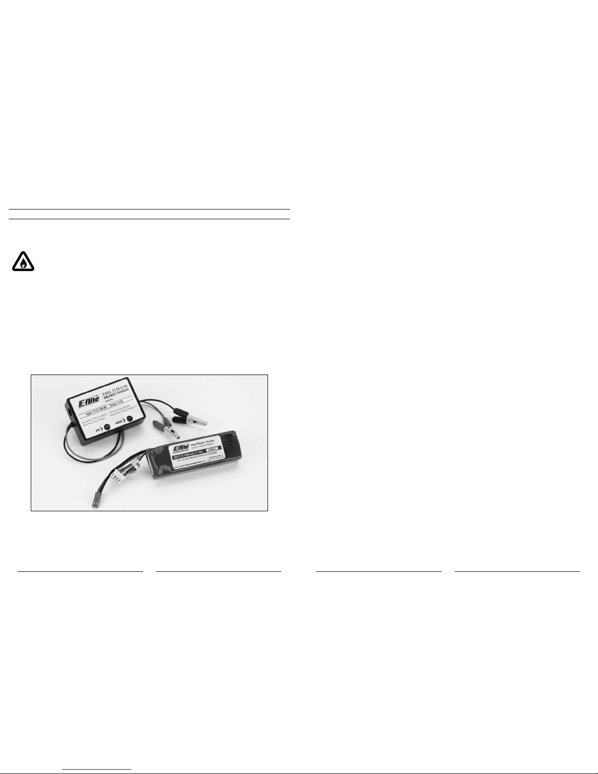
The 3S 11.1V 1000mAh Lithium Polymer Battery Pack (EFLB0997) included with your Blade SR features
Charge Protection Circuitry and Balance Charging via the included 3S 11.1V Lithium Polymer Balancing
Charger (EFLC3105). However, to help ensure a safe charge every time, you MUST read the following
safety instructions and warnings before handling, charging or using the Li-Po battery pack.
Note: Lithium Polymer batteries are significantly more volatile than the alkaline, Ni-Cd or
Ni-MH batteries used in RC applications. All instructions and warnings must be followed
exactly. Mishandling of Li-Po batteries can result in fire.
By handling, charging or using the included Li-Po battery you assume all risks associated with lithium
batteries. If you do not agree with these conditions, return your complete Blade SR model in new, unused
condition to the place of purchase immediately.
• Youmustchargetheincluded3S11.1V1000mAhLi-Pobatterypackinasafeareaawayfromflammable
materials.
• Donotchargethebatterywheninstalledinthehelicopter.
• Neverchargethebatteryunattended.Whenchargingthebatteryyoushouldmonitorthechargingprocess
and react to potential problems that may occur.
• Afterflight,thebatterymustbecooledtoambienttemperaturebeforecharging.
• You MUST use the included 3S 11.1V Li-Po Balancing Charger ONLY. Failure to do so may result in a
fire causing personal injury and/or property damage. DO NOT use an Ni-Cd or Ni-MH charger.
• Ifatanytimeduringthechargeordischargeprocessthebatterybeginstoballoonorswell,discontinue
charging or discharging immediately. Quickly and safely disconnect the battery, then place it in a safe, open
area away from flammable materials to observe it for at least 15 minutes. Continuing to charge or discharge
a battery that has begun to balloon or swell can result in a fire. A battery that has ballooned or swollen even
a small amount must be removed from service completely.
• Intheeventofacrash,youmustquicklyandsafelydisconnectandremovethebatteryfromthemodel,then
place it in a safe, open area away from flammable materials to observe it for at least 15 minutes.
• Storethebatteryatroomtemperatureatapproximately½charge(3.8Vpercell;11.4Vfora3Sbattery
pack) for best results.
• Whentransportingortemporarilystoringthebattery,thetemperaturerangeshouldbefrom40–120degrees
Fahrenheit. Do not store the battery or model in a car or direct sunlight whenever possible. If stored in a hot
car, the battery can be damaged or even catch fire.
• Donotover-dischargethebattery.Dischargingthebatterytoolowcancausedamagetothepack
resulting in reduced performance and duration.
Li-Po cells should not be discharged to below 3V each under load. In the case of the 3S Li-Po
packs used for the Blade SR, you will not want to allow the battery to fall to below 9V during flight.
The Blade SR’s 2-in-1 control unit does not feature a voltage cutoff of any type, so we suggest
that you be extremely aware of the power level of the Li-Po battery pack during flight. If at any
time the helicopter begins to require more throttle than typical to maintain hover or flight, or has
lost significant power, you must land the helicopter and power the motors down IMMEDIATELY to
prevent over-discharge of the Li-Po battery pack. If you continue to run the motors after noticing
a loss in power, it is possible to discharge the Li-Po battery pack too far, causing permanent
damage to the pack.
Over-discharge of the Li-Po battery pack can result in shortened flight times, loss of power output
or failure of the pack entirely.
Ifyouhaveanyfurtherquestionsorconcernsregardingthehandling,chargingand/oruseoftheincludedLi-Pobattery
pack, please contact Horizon Hobby’s Product Support Team at 877-504-0233, Horizon Hobby UK at
+44 (0) 1279 641 097 or Horizon Technischer Service, Germany at +49 4121 46199 66.

8
9
Battery Charging
It is important that you only charge the included 3S 11.1V 1000mAh Li-Po Battery Pack (EFLB0997) with the included
3S11.1VLi-PoBalancingCharger(EFLC3105).YourbatterypackisequippedwithspecialChargeProtectionCircuitry
and a Balance Charge Lead with connector that is only compatible with this charger. Attempting to charge the pack
using another Li-Po charger or non Li-Po compatible charger could result in serious damage. Please familiarize yourself
thoroughly with the Battery Warnings and Guidelines section before continuing.
The included 3S 11.1V Li-Po Balancing Charger will charge a near fully discharged (not over-discharged) 3S 11.1V
1000mAhLi-PoBatteryPackinapproximately1.2–1.5hours.Insomecasesthechargetimemaybeshorter
depending on the actual amount of capacity left in the pack after a flight. NEVER charge the battery unattended.
Note: The Li-Po battery pack included with your Blade SR will arrive partially charged. For this reason the initial
chargemayonlytakeapproximately30–50minutes.
Thechargerrequiresupto1.5ampsof11.5–15-voltDCinputpowerthatcanbesuppliedbytheincludedACto12V
DC, 1.5-amp Power Supply (EFLC4000) for convenient charging anywhere an AC outlet is available. NEVER attempt to
power the charger from an AC outlet without the use of a proper AC to DC adapter/power supply.
Note: When using the AC to DC adapter/power supply, the charger is protected to prevent damage if the
alligator clips touch. However, please take care to ensure that the alligator clips do not cause shorting of
the battery, adapter/power supply, etc. by keeping them clear.
Input power for the charger can also be supplied from a small 12-volt gel cell or car battery.
ThechargerisequippedwithtwoLEDindicatorsmarkedREDandGREENonthelabel.TheseLEDsindicatethe
following (also found on the label of the charger):
• Red Flashing LED Only: Input power with no battery connected
• Red and Green Solid LED: Battery connected and charging
• Red Solid LED Only: Charge complete
• Red and Green Flashing LED: Charge error
Once you have connected the charger to a power source (use care to ensuring proper polarity when connecting the
charger to the power source), its red LED flashes to indicate the charger has power and is ready to begin charging.
Connect the Li-Po battery pack to the charger using the specially marked Balance Charge Lead exiting the battery pack
and the connector labeled with 11.1V on the charger. The connector is keyed to prevent reverse polarity connection.
When the battery is properly connected and charging normally, the red and green LED indicators will glow solid. Once
the battery has been fully charged, the green LED will go out, leaving just the red LED glowing solid. The battery can
now be removed from the charger and installed into the Blade SR for flight.

10
11
Charge Errors and Indications
In the event that both the red and green LEDs flash, a charge error has occurred. Some examples of charge errors and
their indications include:
• AlternatingflashingoftheredandgreenLEDsindicatesthatthechargeprocesshasbeeninterrupted.Ifinput
power to the charger has been interrupted due to disconnection from the power source or a drop in voltage/
current output from the power source, unplug the battery from the charger. Next, check to make sure that
the input power plug from the AC to 12V DC adapter/power supply is connected or that the alligator clips are
firmly and properly attached to the power source. Also be sure that the power source is providing the proper
amountofvoltageandcurrentrequiredtothecharger.
After confirming the connections and that the power source is delivering the necessary voltage and current,
restart the charging process by connecting the battery pack. Continue to monitor the charging process to
ensure that no further charge errors occur.
• SimultaneousflashingoftheredandgreenLEDsindicatethatthevoltageoftheLi-Pobatterypackistoo
low to allow the charging process to begin. In this case the battery may have been over-discharged due to
flying the model too long, or a single cell or even all cells in the battery pack may be damaged. (For more
information on preventing over-discharge of the Li-Po battery pack, see the Battery Warnings and Guidelines
section.)
If after several charging attempts you continue to see this charge error indication, you should remove the
battery pack from service and replace it with a new one.
Ifyouhaveanyfurtherquestionsorconcernsregardingchargeerrorindications,pleasecontactHorizonHobby’s
Product Support Team at 877-504-0233, Horizon Hobby UK at +44 (0) 1279 641 097 or Horizon Technischer Service,
Germany at +49 4121 46199 66.
Installing the Transmitter Batteries
Install the 4 included AA batteries in the transmitter. Check the power level of the batteries and operation of the
transmitter by switching the power switch on (upward). The LCD screen at the top of the transmitter will indicate the
power level of the batteries. If at any time the voltage indicated on the LCD screen falls to 4.5V or less, an alarm will
sound, and it will be necessary to replace the batteries with new ones.
Note:BecausetheHP6DSMtransmitterincludedwiththeBladeSRisequippedwithSpektrum2.4GHzDSM2
technology,itdoesnotrequirethesameinputvoltageorcurrentconsumptionasatypical72MHz
transmitter for proper operation and optimum performance.
Installing the Flight Battery
Use the included hook and loop material for mounting the Li-Po battery pack. We suggest installing the loop (fuzzy)
material on the battery pack and the hook material on the battery support. You should also use the included hook and
loop battery strap for the most secure attachment of the battery to the helicopter.
12
13
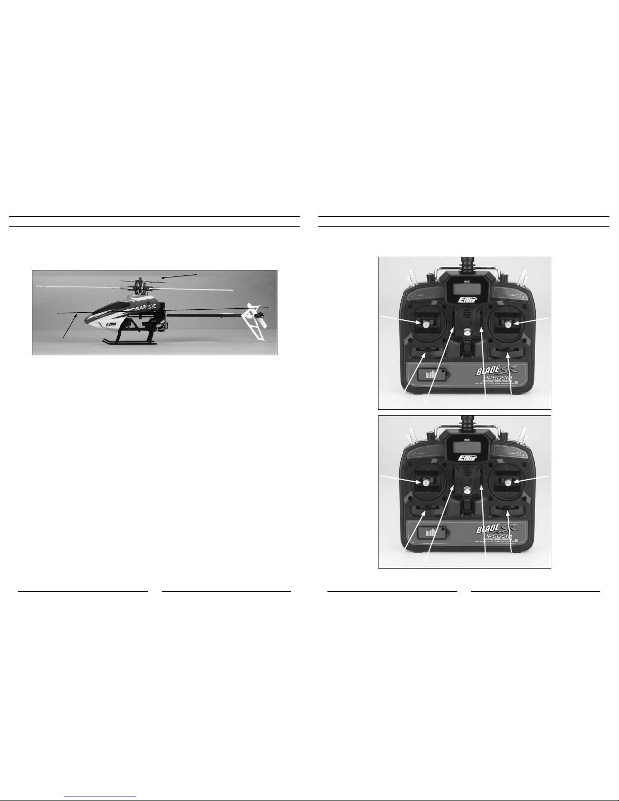
Center of Gravity
Once you have properly installed and secured the battery, check the helicopter’s center of gravity. With the canopy
installed, lift the helicopter by the flybar with the flybar positioned perpendicular to the tail boom. Move the battery
forwardorrearwardasrequiredtoachieveaslightlynosedownorperfectlylevelhelicopterposition.Youshouldalways
check the CG of your Blade SR before flying, especially if you are switching between different sizes and types of battery
packs.
Support by Flybar
Level or Slightly
Downward Angle
Transmitter Control Identification
Note: Before each flight ALWAYS turn the transmitter on before connecting the flight battery to the 2-in-1 unit.
After each flight, you should always disconnect the flight battery from the 2-in-1 unit before powering the
transmitter off.
Throttle Trim
Aileron Trim
Elevator Trim
Rudder Trim
Elevator Trim
Aileron Trim
Throttle Trim
Rudder Trim
Rudder/Throttle
Functions
Rudder/Elevator
Functions
Aileron/Elevator
Functions
Aileron/Throttle
Functions
Mode 1
Mode 2

14
15
Control Test
Although each Blade SR model is test flown at the factory, you should test the controls prior to the first flight to ensure
none of the servos, linkages or parts were damaged during shipping and handling. Before proceeding, unplug the three
bullet connectors between the main motor and ESC and tail motor from the 2-in-1 control unit. It is not safe to perform
the control test with the main or tail motor plugs connected to the 2-in-1 control unit after power up.
Turn the transmitter on first and lower the throttle stick and trim completely. Then, plug the battery into the battery lead
of the 2-in-1 unit.
Mode 2 Mode 1
16
17
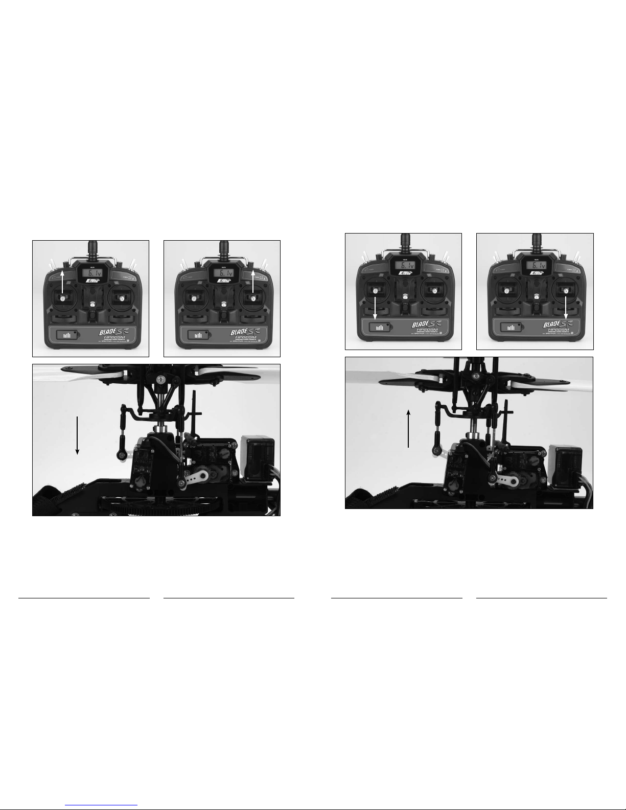
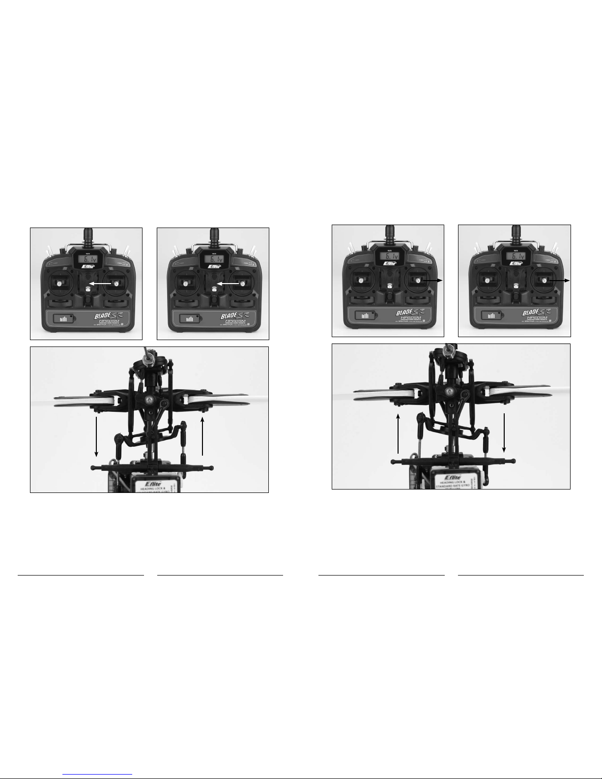
Position the helicopter to view it from the left or right side. Move the left-hand stick up and down to check the collective
pitch control. When the stick is pushed up, the swashplate should lower, increasing the pitch of the main blades.
Mode 2 Mode 1
With the stick pulled back down, the swashplate should raise, decreasing the pitch of the main blades.
Mode 2 Mode 1
18
19
Again viewing the helicopter from the left or right side, move the right-hand stick forward and aft to check elevator pitch
control. When the stick is pushed forward, the swashplate should also tilt forward.
Mode 2 Mode 1
With the stick pulled back, the swashplate will tilt toward the rear.
Mode 2 Mode 1
20
21
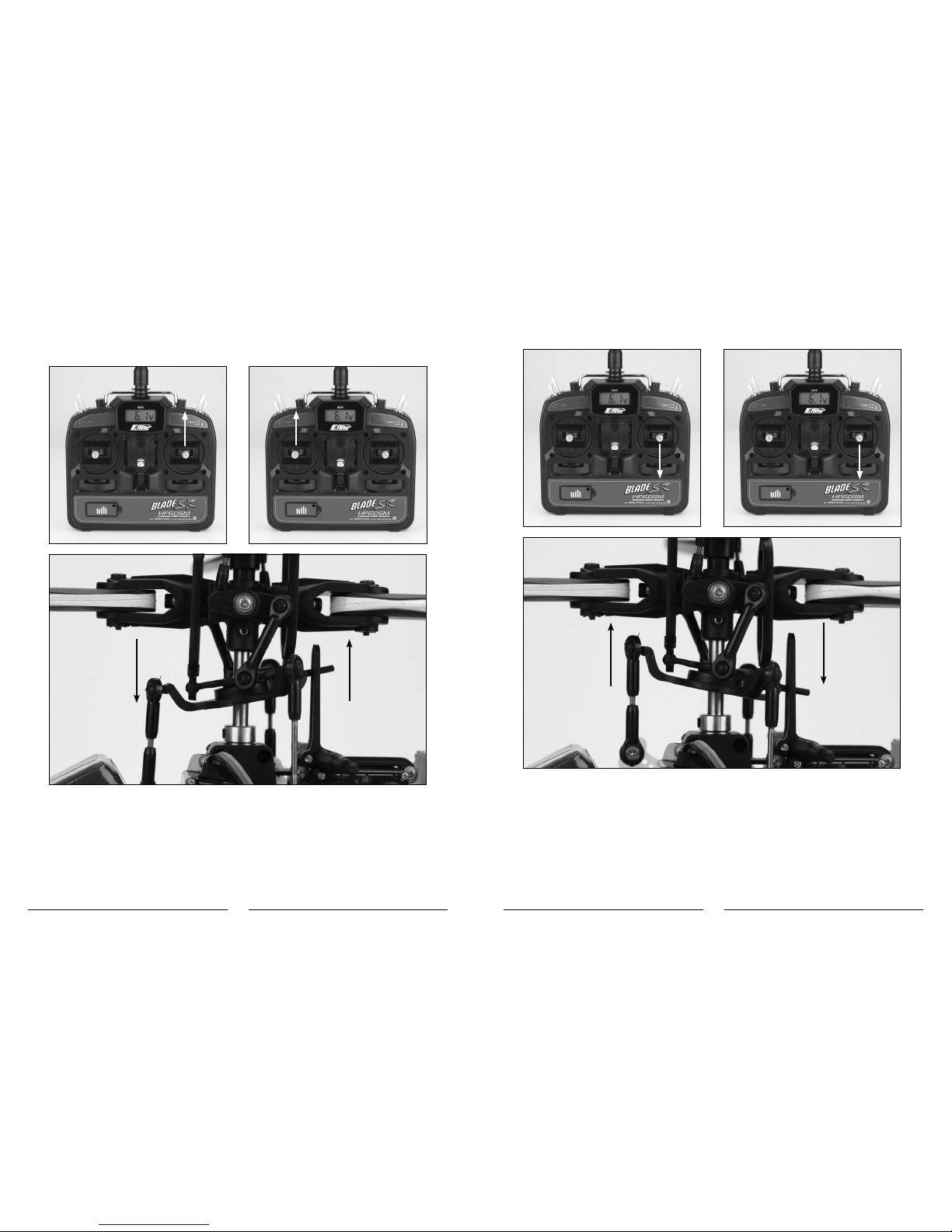
While viewing the helicopter from the rear (tail boom toward you), move the right-hand stick left and right to check
aileron roll control. When the stick is pushed to the left, the swashplate should also tilt left.
Mode 2 Mode 1
With the stick pushed right, the swashplate will tilt to the right.
Mode 2 Mode 1

22
23
If at any time during the test the controls do not respond properly, double-check the positions of the dip switches
located under the door on the bottom left front of the transmitter. These dip switches set the transmitter programming
for functions such as servo reversing, model type and various forms of mixing. Each switch should be set in the
position as shown for proper control of the Blade SR.
For added reference, the following are the functions and available settings for each dip switch (default settings for the
Blade SR are underlined):
Dip Switch 1*
Up–Channel1/Throttlechannelreversed
Down–Channel1/Throttlechannelnormal
*For safety, channel 1/throttle channel reversing can only be changed when the transmitter is powered off. All
other dip switch positions/functions can be changed while the transmitter is powered on.
Dip Switch 2
Up–Channel2/Aileronchannelreversed
Down–Channel2/Aileronchannelnormal
Dip Switch 3
Up–Channel3/Elevatorchannelreversed
Down–Channel3/Elevatorchannelnormal
Dip Switch 4
Up–Channel4/Rudderchannelreversed
Down–Channel4/Rudderchannelnormal
Dip Switch 5
Up–Channel5/Gearchannelreversed
Down–Channel5/Gearchannelnormal
Dip Switch 6
Up–Channel6/Pitchchannelreversed
Down–Channel6/Pitchchannelnormal
Dip Switch 7
Up–HelicopterMode(Channel6becomes
pitch channel)
Down–AirplaneMode(Channel6becomesanextraaileronchannel)

24
25
Dip Switch 8*
Up–120-degreeCyclicCollectivePitchMixing(CCPM)
Down–Standardmixing
*Only functions when in helicopter mode.
Dip Switch 9*
Up–Rudder/Elevatormixing
Down–Nomixing
*Only functions when in airplane mode, and no function if switch 10 is in the up position.
Dip Switch 10*
Up–Elevator/Aileronmixing
Down–Nomixing
*Only functions when in airplane mode, and no function if switch 9 is in the up position.
If the controls still do not respond properly after ensuring the dip switch positions are correct, you should also check
the servo connections to the receiver. The servos should be connected to the corresponding channel on the receiver as
follows (when viewing the helicopter from behind):
AILE(Aileron)Channel–Left-handrearaileronservo
ELEV(Elevator)Channel–Forwardelevatorservo
AUX1(Pitch)Channel–Right-handrearpitchservo
Once you’ve confirmed the proper dip switch positions and servo connections, all controls should be functioning
properly. However, if you continue to encounter any problems with your Blade SR responding properly to the
transmitter, do not fly. Call Horizon Hobby’s Product Support staff at 1-877-504-0233, Horizon Hobby UK at +44 (0)
1279 641 097 or Horizon Technischer Service, Germany at +49 4121 46199 66.
If you’ve confirmed proper control operation of your Blade SR, unplug the flight battery and reconnect the main and tail
motors to the 2-in-1 unit, taking care to connect them to the proper leads using the markings on the label for reference.
2-in-1 Control Unit Description, Arming and Motor Control Test
YourBladeSRisequippedwithalightweightcombinationofmainmotorandtailmotorelectronicspeedcontrols
and main motor and tail motor proportional mixer. The 2-in-1 has an 8-amp brushless ESC for the main motor that is
specificallydesignedforuseinhelicoptermodels.TheESCisnotprogrammableforuseinotherapplications;however,
itisequippedwithfeaturesandfunctionsthatoptimizeitsperformancefortheBladeSR.Thesefeaturesandfunctions
include:
•“Soft”LowVoltageCutoff
TheESCfeaturesa“soft”lowvoltagecutoff(LVC)thatoccurswhenthebatteryreachesapproximately9V
underload.Thishelpsprevent“deep”over-dischargeoftheLi-Pobatteryduringuse.PleaseseetheBattery
Warnings and Guidelines section for more information regarding the soft LVC feature and how to prevent over-
discharge of the Li-Po battery.
•Soft(Slow)Start
The soft (slow) start function of the ESC is intended to help prevent potential damage of the Gear train, motor
and ESC by slowly increasing power to the motor (particularly when the rotor blades are not already spinning).
The first time you power up the ESC after it has been powered on and armed, it will take approximately 15
seconds for the ESC/motor to reach the power level you initially set with the throttle stick/curve. This means
you will need to wait approximately 15 seconds before attempting any aggressive maneuvering to allow the
power system to reach the set level of power first.
Any time (after the initial soft startup occurs) the ESC/motor have been powered down completely (to 0%
power) for approximately 15 seconds or more, the soft start will occur again. This is particularly helpful if
you land the helicopter to make an adjustment as you will not need to rearm the ESC in order to perform a
soft startup. It is simply best to wait approximately 15 seconds before powering up the ESC/motor again for
flight.
•FastStart
The fast start function of the ESC allows any level of power to be applied almost immediately after ESC/
motor have been powered down completely (to 0% power) for any amount of time less than approximately
15 seconds. This is particularly helpful if you accidentally bump the Throttle Hold switch or when aborting an
auto-rotation attempt as it will allow the ESC/motor to reach any power level you have set with the throttle
stick/curve almost immediately when the Throttle Hold switch is set back to the OFF (0) position.
The following checklist contains the steps you must follow to ensure proper arming and operation of the 2-in-1 unit, as
well as proper motor response.
• BeforeeachflightALWAYSturnthetransmitteronbeforeconnectingtheflightbatterytothe2-in-1unit.Never
connect the flight battery to the 2-in-1 unit before powering the transmitter on first. After each flight, always
disconnect the flight battery from the 2-in-1 unit before powering the transmitter off.
Note: The antennas exiting the Spektrum AR6100e receiver should extend outward (to the left and right of the
helicopter) as much as possible for the best overall performance. Be sure to double-check the position
and orientation of both antennas before each flying session, especially if the helicopter was taken out of
a box or carrying case.
• Boththethrottle(left-hand)stickandthrottletrimMUSTbeintheirlowestpossiblepositioninorderforthe
2-in-1 unit to arm. The flight mode (F MODE) switch must also be in the normal (0) flight mode position with
the switch toggled toward the back of the transmitter for the unit to arm.
If this is the first test flight, or a test flight following repairs, you will also want to center the rudder, aileron
and elevator trims (reference Transmitter Control Identification on page 13).
• Turnthetransmitteronandensureithasadequatebatterypower,asdisplayedbytheLCDscreenatthetop
of the transmitter. It is now safe to connect the flight battery to the 2-in-1 unit.

26
27
Note: Do not move or sway the helicopter until the red LED on the gyro illuminates solidly. This will be covered
in more detail in the next section.
• Withbatterypowerapplied,andoncetheorangeLEDoftheSpektrumAR6100ereceiverglowssolidlyto
indicateapositivelinktothetransmitter,youwillheartwo“beeps”fromthe2-in-1,indicatingithasarmed
properly. The final step of the initialization is for the red LED on the gyro to illuminate solidly.
• Whenyouhaveheardtwo“beeps”,theunitisarmedandreadyforflight.Usecautionasboththemainand
tail rotors will now spin with throttle stick input. For safety, once the unit is armed, the main and tail motors
will not spin with the throttle stick and trim in their lowest positions. However, we also suggest setting the
throttle hold (TH HOLD) switch in the on (1) position, toward the front of the transmitter, once the 2-in-1 unit
has armed. This will keep the motors and rotor blades from spinning while you handle the helicopter and
transmitter.
If you have not set the throttle hold switch to the on position, or after you set the switch to the off (0) position
toward the back of the transmitter, DO NOT advance the throttle stick until you are clear of the rotor blades
and ready to fly.
Note: If you do not hear two beeps or if you hear a constant series of beeps after battery power is applied, the
2-in-1 unit has not armed properly. A constant series of beeps indicates the throttle is set too high for
initialization. Please review the following.
qConfirm that the throttle stick is in the lowest possible position and that the throttle trim is set in
approximately the middle position.
qConfirmthattheFlightMode(FMODE)switchissettothe“Normal”(0)position.
qConfirm you have a positive RF link between the transmitter and receiver. First, check to be sure the
transmitterhasbeenpoweredonandhasanadequatelevelofbatterypower.Ifthetransmitterispoweredon
and functioning properly, disconnect the flight battery from the 2-in-1, then reconnect it. Watch for the orange
LED of the receiver to begin glowing solidly, and once it does, the 2-in-1 unit should arm normally.
If your 2-in-1 unit will not arm after following the guidelines as listed above, contact Horizon Hobby’s Product
Support staff at 1-877-504-0233, Horizon Hobby UK at +44 (0) 1279 641 097 or Horizon Technischer
Service, Germany at +49 4121 46199 66.
• Onceyouhaveplacedthehelicopterinasafearea,freeofobstructions,andareclearoftherotorblades,
you can safely begin to power up the model to check for proper operation of the motors.
• Advancethethrottlestickupwardslowly,justuntilboththemainandtailrotorbladesbegintospin.DONOT
attempt to fly the helicopter at this time. Note the direction the main and tail rotor blades spin. The main rotor
blades should spin clockwise when viewed from the top, with the tail rotor blade spinning clockwise when
viewed from the right-hand side of the helicopter. If the main rotor blades are operating in the wrong direction,
simply reverse the position of any two motor wire lead connections to the 2-in-1 unit.
• Withthetailmotor/rotorspinningatalowrpm,checkthatthetailrotorisrespondingproperlytotransmitter
inputs. When inputting a slight amount of right rudder, the tail rotor rpm’s should increase, pushing the nose
of the helicopter to the right. If you are on carpet, grass, or an otherwise uneven surface, be very careful
not to allow the helicopter to catch the vertical fin when testing the tail rotor control on the ground (or during
liftoff when beginning a flight).
After confirming that both rotor blades are rotating in the correct directions, and the tail rotor is responding properly to
rudder inputs, your Blade SR is ready for flight. However, please be sure to review the following sections of the manual
BEFORE proceeding with the first flight.
Gyro Initialization, Response Test and Adjustment
YourBladeSRmodelisequippedwithanE-fliteG110MicroHeadingLockGyro.Thisgyrooffersanexcellentblendof
size, weight, features and performance.

28
29
Initialization and Response Test
The following checklist includes the steps to properly initialize and operate the gyro.
• Afterconnectingtheflightbatterytothe2-in-1unit,donotmoveorswaythehelicopter.Allowittoremain
motionless until the red LED on the gyro illuminates solidly, indicating that the gyro has initialized properly and
is ready for use.
Note: It is extremely important that you do not move or sway the helicopter after powering it on and before the
gyroinitializes.Thegyromustbeallowedadequatetimetorecordtheneutralpositioninordertoinitialize
for proper operation. If you ever accidentally move the helicopter after powering it on and before the gyro
initializes, power the helicopter off (by disconnecting the flight battery from the 2-in-1 unit) and repeat the
correct process.
• Oncethegyroinitializesproperly,andbeforemakingyourfirstflight,confirmthatthegyroisresponding
properly to the movements of the helicopter and providing proper inputs to the tail rotor in order to
counteract any unwanted changes in yaw.
For added safety during the test, disconnect the main motor from the 2-in-1 control unit.
•ThensecurethehelicopterandensurethatallobjectsarefreeandclearofthetailrotorbladesReconfirming
that the main motor has been disconnected from the 2-in-1 control unit, advance the throttle/collective stick
onthetransmittertoapproximately1/4–1/2travel.Usecaution,asthetailmotormaybegintospinthetail
rotor blade.
• Nowitisnecessarytoconfirmthatthetailmotor/rotorrespondsproperlytoinputsfromthegyro.While
holdingthehelicoptersecurelyandensuringthatallobjectsarefreeandclearfromthetailmotor,quickly
twist the nose of the helicopter to the left. If the tail motor/rotor is responding properly to inputs from the
gyro, the rpm’s will increase to counteract the nose twisting to the left, in order to bring the nose back to the
right.Whenquicklytwistingthenoseofthehelicoptertoright,therpm’sshoulddecreaseorstopentirely.
If the tail motor/rotor is not responding properly, use the reverse switch located on the gyro to reverse the
direction of response.
• Afterconfirmingthatthetailmotor/rotorrespondsproperlytoinputsfromthegyro,disconnectthe
battery from the 2-in-1 control unit. Then, power down the transmitter and reconnect the main motor to
the 2-in-1 unit.
Now that you’ve confirmed the gyro provides proper inputs to the tail motor/rotor, review the following
sections of the manual BEFORE proceeding with the first flight.
Gain Adjustments
The G110 offers optional-use remote mode selection and gain adjustment features. These features allow the gyro
mode (Standard Rate or Heading Lock) and gain values to be set remotely in the transmitter. However, for simplified
use, while maintaining maximum performance in the Blade SR, these features will not be utilized (they are usually best
utilized when using a programmable computer transmitter).
• Becauseyouwillnotbeutilizingtheremotemodeselectionandgainadjustmentfeaturesofthegyro,the
gyro’s yellow-colored auxiliary (AUX) lead and connector will not be plugged into the receiver. This is not a
problem as the gyro will always be in the heading lock mode and the gain value can be set using the gain
value adjustment pot located on the gyro itself.
• Aftermakingtheinitialtestflight,youmayfindthatitisnecessarytoadjustthegyrogainsettingvalueprior
tosubsequenttestflightsinordertoachievethebestpossibleperformance.Thegoal,whenusingaheading
lock type gyro, is to find the highest gain setting value at which the tail/nose of the helicopter does not twitch
quickly(oscillate)fromsidetosideinallareasofflight(includingfastforwardflightanddescents).Inthecase
of the G110 in the Blade SR, we find that it is typical to have the gain setting adjustment pot set as shown
below, which is only a few degrees off of full counterclockwise.
Optimum Range
• Small,airswooshingnoisesalongwithasmallamountofmovementsidetosideisnormalforadirect-drive
tail system, like that found on the Blade SR. Don’t confuse this for a gain setting that is too high.
Note: If the tail spins in one direction or the other as you are trying to lift off, please check the gyro gain. It
may be adjusted too high or too low.
30
31
Trim Adjustments
During flight, it may be necessary to make some small adjustments to the rudder trim in order to prevent the nose/
tailofthemodelfrom“drifting”totheleftorrightwhentherudderstickisintheneutralposition.Typically,onlyasmall
amount of adjustment may be necessary.
Note: It is always best to avoid sudden temperature and environmental condition changes when using a gyro.
For example, it is best to not fly a model on a very hot (or cold) day immediately after removing it from
an air-conditioned (or heated) vehicle. It is also best to keep the gyro out of direct sunlight and away from
any heat-generating sources on the model.
To help the gyro better acclimate to temperature and environmental conditions at the flying field, it is best to let your
BladeSRstandintheenvironmentforapproximately10–15minutesbeforeflying,allowingthetemperatureofthe
gyro sensor to stabilize. If you do not allow the temperature to stabilize, you may experience radical trim changes that
requiresignificantadjustmentsoftheruddertrimduringflight.
Servo Mode Setting
TheG110isequippedwithaswitchandsoftwarethatallowsitsperformancetobeoptimizedforusewithmostanalog
and some digital servos. The servo mode selection switch is found on the side of the gyro.
However, because the Blade SR uses an ESC and motor to control the tail, you must be certain that the servo mode
selection switch on the gyro is set to standard servo mode to ensure proper response and performance of the gyro. If
it is set to digital servo mode, the electronic speed control and tail motor will not respond properly to inputs from the
gyro or transmitter. This could even cause failure of the motor, ESC or both.
Installing the Optional Training Gear
IftheBladeSRisyourfirstsingle-rotorand/orcollective-pitchequippedhelicoptermodel,wesuggestthatyouinstall
the optional Training Gear Set (EFLH1527) before making your first flight. The training gear helps to further increase the
stability of the model while also providing added support and cushioning to prevent tip-overs and damage to the model
from abrupt landings.
Installing the training gear takes only a few minutes following these steps.
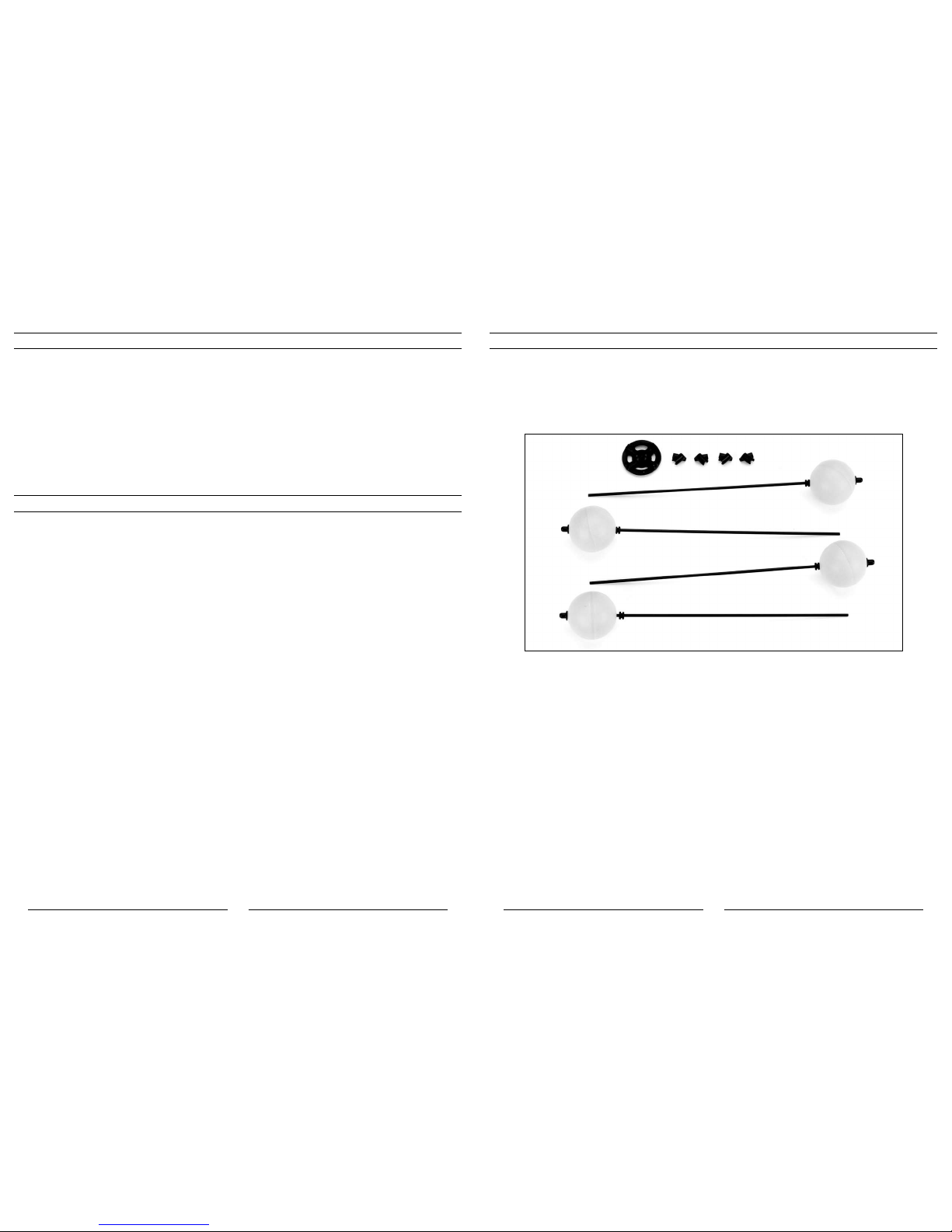
• Thetraininggearsetincludesfourplasticballs,fourballgrommets,fourtraininggearrods,fourrodend
caps, four training gear rod to landing skid attachments and one training gear rod mounting base.

32
33
• Locatethefourtraininggearrodtolandingskidattachments.Snaptheattachmentstothelandingskidsas
shown below.
• Afterinstallingallfourattachments,locatethefourtraininggearrodsandrodmountingbase.Notethatthe
rodmountingbasehasa“coned”shapetoit.The“pointed”sideofthebasewillfaceupwardtowardthe
bottom of the helicopter when properly installed. The base also has two different angles where the gear rods
attach. It is important to orient the base so that the large angle is facing forward and backward.
• Carefullypasseachoftherodsthroughtheholesintheattachmentsonthelandingskidsandintothe
channels on the base. The rods will pass through the front holes of the forward attachments, and the back
holes of the rear attachments. You may find it necessary to apply some light pressure to the rods, base and
landingskidswheninstallingallfourrodsinthebase.Thisistypical;however,takecaretonotdamageany
of the parts.
Once all four rods are installed, note that the landing skids may be pulled slightly inward under their pressure.
This is also typical as the pressure helps to keep the training gear in place.
• Checkthefitmentoftheplasticballsonthetraininggearrod.Adjustthepositionofthegrommetsthatwere
factory-installed on each rod until they are just touching each plastic ball. The grommets should then be
positioned so that the ball can spin freely on the rod, without too much movement side-to-side between the
keepers.
Your Blade SR is now ready for flight with the training gear installed.
34
35
Understanding the Primary Flight Controls
If you are not familiar with the controls of your Blade SR, please take a few minutes to familiarize yourself with them
before attempting your first flight.
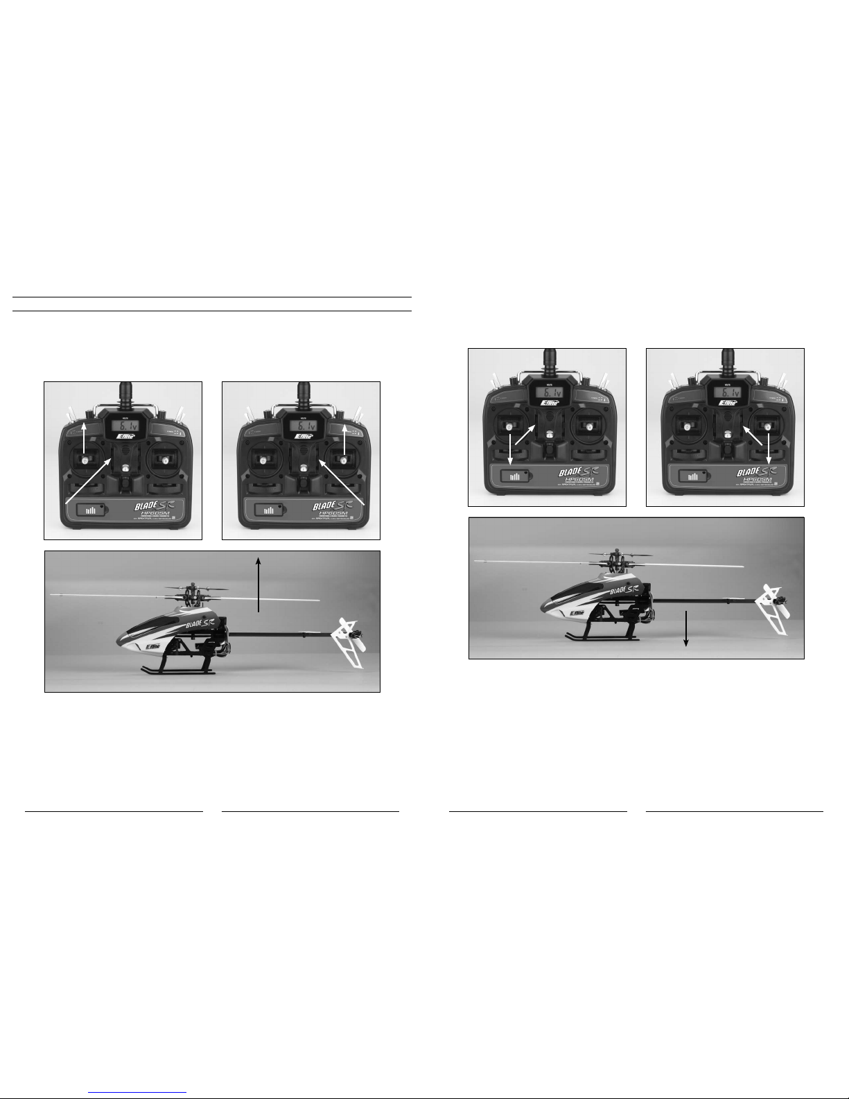
The left-hand stick on the transmitter controls both throttle/collective pitch (climb/descend) and rudder (yaw left/
right). When the left-hand stick and throttle trim lever are in their lowest positions, the main rotor blades will not spin.
Advancing the stick upward will increase the speed and pitch of the main rotor blades. Increasing the speed and pitch
of the main rotor blades will cause the model to climb.
Mode 2 Mode 1
Climb
Decreasing the speed and pitch of the main rotor blades by lowering the left-hand stick will cause the model to
descend.
When you are in stunt flight mode (with the F MODE switch toggled toward the front of the transmitter),
lowering the left-hand stick will actually cause the speed of the main rotor blades to increase while also
increasing the amount of negative pitch the main rotor blades can offer. This allows the model to be flown
inverted and to perform basic aerobatic maneuvers.
Mode 2 Mode 1
Descend
After lifting the model off the ground you can balance the throttle/pitch by carefully moving the left-hand stick up and
down so the model will hold a stationary hover without climbing or descending.
You can also use the throttle trim to adjust the throttle/collective pitch value for a given stick position. For example,
raising the throttle trim will allow the model to hover at a lower throttle stick position. It will also offer more total
positive pitch at the highest stick position, and less negative pitch at the lowest position. In most cases it is preferred
topositionthethrottletrimsoitoffersanequalamountofpositiveandnegativepitchwhenthestickisinthehighest
and lowest positions.
36
37
Also, if you do raise the throttle trim when in the normal flight mode, you MUST remember to lower it (and the throttle
stick) to the lowest possible position IMMEDIATELY in the event of a crash or rotor blade strike. Even if the motors
are trying to spin at the lowest speed possible, they can still pull enough current to damage the ESCs of the 2-in-
1unitiftherotorbladesarestalled,whichmayrequirereplacementofthe2-in-1unit.Ifyouareinthestuntflight
mode (and also helpful when you are in the normal flight mode), it is usually best to utilize the throttle hold function
of the transmitter in the event of a crash or rotor blade strike by toggling the TH HOLD switch toward the front of the
transmitter.
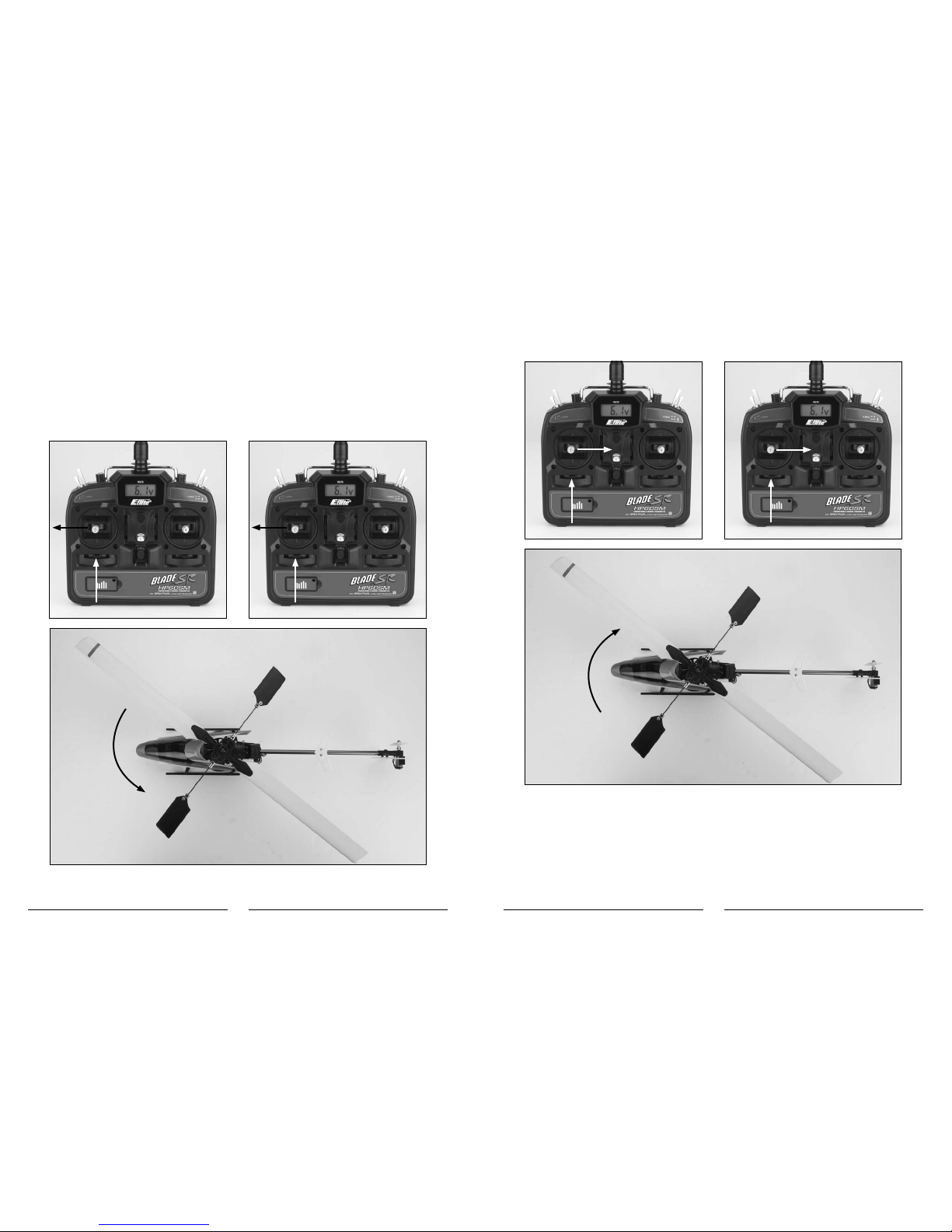
Moving the left-hand stick to the left will turn (yaw) the nose of the helicopter to the left about the axis of the main shaft.
This is accomplished by decreasing the speed of the tail rotor blade.
Nose Yaw Left
Mode 2 Mode 1
Moving the stick to the right will turn (yaw) the nose of the helicopter to the right about the axis of the main shaft. This
is accomplished by increasing the speed of the tail rotor blade.
Nose Yaw Right
Mode 2 Mode 1

38
39
You can use the rudder trim to help keep the nose of the helicopter from rotating to the left or right when in hover
with no rudder stick input. For example, if the nose of the helicopter drifts to the right when in hover, add left rudder
trim until the nose stays as close to straight as possible. Also note that further adjustments to the rudder trim can be
madeusingthemainmotorproportionalmixtrimmerpotasoutlinedinthe“TailRotorProportionalMixTrimmerPot
Adjustment”sectionofthemanual.
The right-hand stick controls both elevator (pitch fore/aft) and aileron (roll). Pushing the stick forward will pitch the nose
of the helicopter downward, allowing the helicopter to be flown forward.
Mode 2 Mode 1
Heli Moves Forward
Pulling the stick backward will pitch the tail of the helicopter downward, allowing the helicopter to be flown backward.
Mode 2 Mode 1
Heli Moves Backward
The elevator trim can be used to help keep the helicopter from drifting forward or backward when in hover with no
elevator stick input. For example, if the helicopter drifts forward when in hover, pull the elevator trim downward until the
helicopter hovers as level as possible with no forward drifting.
Table of contents
Other E-flight Motorized Toy Car manuals


