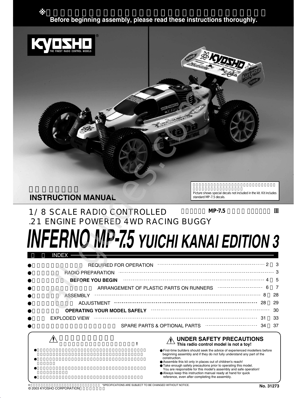
Kyosho INFERNO MP7.5 Sports 3 readyset User manual
Other Kyosho Motorized Toy Car manuals

Kyosho
Kyosho MINI-Z Racer AWD MA-010 Type User manual

Kyosho
Kyosho MINI-Z Racer MR-015 RM Type User manual

Kyosho
Kyosho MINI-Z Racer MR-015 RM Type User manual

Kyosho
Kyosho USA-1 Monster Truck 3165 User manual

Kyosho
Kyosho Integra User manual

Kyosho
Kyosho Mini-Z Racer MR-03N HM Type User manual

Kyosho
Kyosho Mini Z AWD MA-010 DWS ASF 2.4GHz User manual

Kyosho
Kyosho MINI-Z Racer AWD MA-010 Type User manual

Kyosho
Kyosho MotorSports 2020 Mercedes-AMG GT3 readyset User manual

Kyosho
Kyosho MINI-Z Racer MR-03W MM Type User manual

Kyosho
Kyosho GP TR-15 MONSTER TOURING 4WD User manual

Kyosho
Kyosho V-One RR Evo User manual

Kyosho
Kyosho V-oneS III User manual

Kyosho
Kyosho Mini-Z Racer MR-015 RM Type User manual

Kyosho
Kyosho DRX User manual

Kyosho
Kyosho Inferno neo ST Race Spec User manual

Kyosho
Kyosho MINI-Z Racer MR-02 RM Type User manual

Kyosho
Kyosho RAGE VE User manual

Kyosho
Kyosho Ford RS-200 User manual

Kyosho
Kyosho Inferno MP9 User manual