E.H. Wachs 08-051-MAN User manual

Subsea Wire Saw
User’s Manual
Copyright © 2009 E.H. Wachs. All rights reserved.
This manual may not be reproduced in whole or in part
without the written consent of E.H. Wachs.
E.H. Wachs
600 Knightsbridge Parkway
Lincolnshire, IL 60069
www.ehwachs.com
E.H. Wachs Part No. 08-051-MAN
Rev. 1-0709, July 2009
Revision History:
Original March 2009
Rev. 1 July 2009

Subsea Wire Saw User’s Manual
Part No. 08-051-MAN, Rev. 1-0709 E.H.Wachs

Table of Contents
E.H. Wachs Part No. 08-051-MAN, Rev. 1-0709 i
Table of Contents
Chapter 1: About the Subsea Wire Saw . . . . . . . . . . . . . . . . . . . . . . . . . . . . . . . . . . . . . . . . . . 1
Purpose of This Manual . . . . . . . . . . . . . . . . . . . . . . . . . . . . . . . . . . . . . . . . . . . . . . . . . . . . . . . . . 1
How to Use The Manual . . . . . . . . . . . . . . . . . . . . . . . . . . . . . . . . . . . . . . . . . . . . . . . . . . . . . . . . 1
Symbols and Warnings . . . . . . . . . . . . . . . . . . . . . . . . . . . . . . . . . . . . . . . . . . . . . . . . . . . . . . . . . 2
Manual Updates and Revision Tracking . . . . . . . . . . . . . . . . . . . . . . . . . . . . . . . . . . . . . . . . . . . . 3
Equipment Description . . . . . . . . . . . . . . . . . . . . . . . . . . . . . . . . . . . . . . . . . . . . . . . . . . . . . . . . . 3
Subsea Wire Saw Models . . . . . . . . . . . . . . . . . . . . . . . . . . . . . . . . . . . . . . . . . . . . . . . . . . . . 4
Cutting Wire Drive System . . . . . . . . . . . . . . . . . . . . . . . . . . . . . . . . . . . . . . . . . . . . . . . . . . . 4
Feed System . . . . . . . . . . . . . . . . . . . . . . . . . . . . . . . . . . . . . . . . . . . . . . . . . . . . . . . . . . . . . . . 5
Clamping System . . . . . . . . . . . . . . . . . . . . . . . . . . . . . . . . . . . . . . . . . . . . . . . . . . . . . . . . . . . 7
Topside Control Panel . . . . . . . . . . . . . . . . . . . . . . . . . . . . . . . . . . . . . . . . . . . . . . . . . . . . . . . 9
Rigging the Machine . . . . . . . . . . . . . . . . . . . . . . . . . . . . . . . . . . . . . . . . . . . . . . . . . . . . . . . 10
Lifting for Vertical Cut . . . . . . . . . . . . . . . . . . . . . . . . . . . . . . . . . . . . . . . . . . . . . . . . . . 10
Lifting for Horizontal Cut . . . . . . . . . . . . . . . . . . . . . . . . . . . . . . . . . . . . . . . . . . . . . . . . 11
Storing the Machine . . . . . . . . . . . . . . . . . . . . . . . . . . . . . . . . . . . . . . . . . . . . . . . . . . . . . . . . 11
Chapter 2: Safety . . . . . . . . . . . . . . . . . . . . . . . . . . . . . . . . . . . . . . . . . . . . . . . . . . . . . . . . . . . . 19
Operator Safety . . . . . . . . . . . . . . . . . . . . . . . . . . . . . . . . . . . . . . . . . . . . . . . . . . . . . . . . . . . . . . 19
Safety Symbols . . . . . . . . . . . . . . . . . . . . . . . . . . . . . . . . . . . . . . . . . . . . . . . . . . . . . . . . . . . 20
Protective Equipment Requirements . . . . . . . . . . . . . . . . . . . . . . . . . . . . . . . . . . . . . . . . . . . 21
Safety Labels . . . . . . . . . . . . . . . . . . . . . . . . . . . . . . . . . . . . . . . . . . . . . . . . . . . . . . . . . . . . . . . . 21
Chapter 3: Operating Instructions . . . . . . . . . . . . . . . . . . . . . . . . . . . . . . . . . . . . . . . . . . . . . . 23
Tensioning the Cutting Wire . . . . . . . . . . . . . . . . . . . . . . . . . . . . . . . . . . . . . . . . . . . . . . . . . . . . 23
Setting the Clamp Arms for the Pipe Size . . . . . . . . . . . . . . . . . . . . . . . . . . . . . . . . . . . . . . . . . . 25
WS-3012 Pipe Size Settings . . . . . . . . . . . . . . . . . . . . . . . . . . . . . . . . . . . . . . . . . . . . . . . . . 25
WS-3616 Pipe Size Settings . . . . . . . . . . . . . . . . . . . . . . . . . . . . . . . . . . . . . . . . . . . . . . . . . 26
WS-5230 Pipe Size Settings . . . . . . . . . . . . . . . . . . . . . . . . . . . . . . . . . . . . . . . . . . . . . . . . . 27
Positioning the Clamp Arms . . . . . . . . . . . . . . . . . . . . . . . . . . . . . . . . . . . . . . . . . . . . . . . . . 28
Connecting the Hydraulic Hoses . . . . . . . . . . . . . . . . . . . . . . . . . . . . . . . . . . . . . . . . . . . . . . . . . 29
Mounting the Machine on the Pipe . . . . . . . . . . . . . . . . . . . . . . . . . . . . . . . . . . . . . . . . . . . . . . . 30
Performing the Cut . . . . . . . . . . . . . . . . . . . . . . . . . . . . . . . . . . . . . . . . . . . . . . . . . . . . . . . . . . . . 31
Removing the Machine . . . . . . . . . . . . . . . . . . . . . . . . . . . . . . . . . . . . . . . . . . . . . . . . . . . . . . . . 34
Chapter 4: Maintenance . . . . . . . . . . . . . . . . . . . . . . . . . . . . . . . . . . . . . . . . . . . . . . . . . . . . . . 39
Lubrication . . . . . . . . . . . . . . . . . . . . . . . . . . . . . . . . . . . . . . . . . . . . . . . . . . . . . . . . . . . . . . . . . . 39
Replacing the Cutting Wire . . . . . . . . . . . . . . . . . . . . . . . . . . . . . . . . . . . . . . . . . . . . . . . . . . . . . 41
Replacing the Mounting Shoes . . . . . . . . . . . . . . . . . . . . . . . . . . . . . . . . . . . . . . . . . . . . . . . . . . 43
Replacing the Wheel Liners . . . . . . . . . . . . . . . . . . . . . . . . . . . . . . . . . . . . . . . . . . . . . . . . . . . . . 43
Tension and Idler Wheels . . . . . . . . . . . . . . . . . . . . . . . . . . . . . . . . . . . . . . . . . . . . . . . . . . . 44
Drive Wheel . . . . . . . . . . . . . . . . . . . . . . . . . . . . . . . . . . . . . . . . . . . . . . . . . . . . . . . . . . . . . . 48

Subsea Wire Saw User’s Manual
ii Part No. 08-051-MAN, Rev. 1-0709 E.H.Wachs
Chapter 5: Parts List and Ordering Information . . . . . . . . . . . . . . . . . . . . . . . . . . . . . . . . . . 51
Ordering Information . . . . . . . . . . . . . . . . . . . . . . . . . . . . . . . . . . . . . . . . . . . . . . . . . . . . . . . . . . 51
Ordering Replacement Parts . . . . . . . . . . . . . . . . . . . . . . . . . . . . . . . . . . . . . . . . . . . . . . . . . 51
Repair Information . . . . . . . . . . . . . . . . . . . . . . . . . . . . . . . . . . . . . . . . . . . . . . . . . . . . . . . . 51
Warranty Information . . . . . . . . . . . . . . . . . . . . . . . . . . . . . . . . . . . . . . . . . . . . . . . . . . . . . . 52
Return Goods Address . . . . . . . . . . . . . . . . . . . . . . . . . . . . . . . . . . . . . . . . . . . . . . . . . . . . . . 52
Parts Lists and Layout Drawings . . . . . . . . . . . . . . . . . . . . . . . . . . . . . . . . . . . . . . . . . . . . . . . . . 52
WS-3012 . . . . . . . . . . . . . . . . . . . . . . . . . . . . . . . . . . . . . . . . . . . . . . . . . . . . . . . . . . . . . . . . 53
WS-3616 . . . . . . . . . . . . . . . . . . . . . . . . . . . . . . . . . . . . . . . . . . . . . . . . . . . . . . . . . . . . . . . . 60
WS-5230 . . . . . . . . . . . . . . . . . . . . . . . . . . . . . . . . . . . . . . . . . . . . . . . . . . . . . . . . . . . . . . . . 68

Chapter 1, About the Subsea Wire Saw
E.H. Wachs Part No. 08-051-MAN, Rev. 1-0709 1
Chapter 1
About the Subsea
Wire Saw
PURPOSE OF THIS MANUAL
This manual explains how to operate and maintain the sub-
sea wire saw. It includes instructions for set-up, operation,
and maintenance. It also contains parts lists, diagrams, and
service information to help you order replacement parts and
perform user-serviceable repairs.
Before operating the subsea wire saw, you should read
through this manual and become familiar with all instruc-
tions.
HOW TO USE THE MANUAL
Throughoutthismanual,refer
to this column for warnings,
cautions, and notices with
supplementary information.
This manual is organized to help you quickly find the infor-
mation you need. Each chapter describes a specific topic on
using or maintaining your equipment.
Each page is designed with two columns. Thislarge column
on the inside of the page contains instructions and illustra-
tions. Use these instructions to operate and maintain the
equipment.
The narrower column on the outside contains additional
information such as warnings, special notes, and defini-
tions. Refer to it for safety notes and other information.
In This Chapter
PURPOSE OF THIS MANUAL
HOW TO USE THE MANUAL
SYMBOLS AND WARNINGS
MANUAL UPDATES AND
REVISION TRACKING
EQUIPMENT DESCRIPTION

Subsea Wire Saw User’s Manual
2 Part No. 08-051-MAN, Rev. 1-0709 E.H.Wachs
SYMBOLS AND WARNINGS
The following symbols are used throughout this manual to
indicate special notes and warnings. They appear in the out-
side column of the page, next to the section they refer to.
Make sure you understand what each symbol means, and
follow all instructions for cautions and warnings.
A WARNING alert with the
safety alert symbol indicates
a potentially hazardous situa-
tion that could result in seri-
ous injury or death.
A CAUTION alert with the
safety alert symbol indicates
a potentially hazardous situa-
tion that could result in
minor or moderate injury.
A CAUTION alert with the
damage alert symbol indi-
cates a situation that will
result in damage to the
equipment.
An IMPORTANT alert with
the damage alert symbol indi-
cates a situation that may
result in damage to the
equipment.
WARNING
This is the safety alert symbol. It is used
to alert you to potential personal injury
hazards. Obey all safety messages that
follow this symbol to avoid possible
injury or death.
CAUTION
CAUTION
This is the equipment damage alert
symbol. It is used to alert you to poten-
tial equipment damage situations.
Obey all messages that follow this sym-
bol to avoid damaging the equipment or
workpiece on which it is operating.
IMPORTANT
Chapter 1, About the Subsea Wire Saw: Manual Updates and Revision Tracking
E.H. Wachs Part No. 08-051-MAN, Rev. 1-0709 3
A NOTE provides supple-
mentary information or oper-
ating tips.
MANUAL UPDATES AND REVISION TRACKING
Current versions of E.H.
Wachs Company manuals
are also available in PDF for-
mat. You can request an
electroniccopy of this manual
by emailing customer service
Occasionally, we will update manuals with improved opera-
tion or maintenance procedures, or with corrections if nec-
essary. When a manual is revised, we will update the
revision history on the title page.
You may have factory service or upgrades performed on the
equipment. If this service changes any technical data or
operation and maintenance procedures, we will include a
revised manual when we return the equipment to you.
EQUIPMENT DESCRIPTION
The subsea wire saw is designed to cut submerged pipe of
varying materials and thicknesses. The machine operates on
hydraulic power, and is controlled remotely using the
Wachs topside control panel (TCP).
The saw uses a continuous-loop diamond cutting wire and a
hydraulic feed system that advances the cutting wire
through the pipe. Using a wire rather than a blade provides
more reliable cutting on varied pipe materials, and helps
avoid binding of the cutting mechanism if the pipe bends
and pinches while the saw is engaged.
The subsea wire saw has three hydraulic drive circuits:
• Cutting drive: operates the drive wheel that drives the
cutting wire.
• Feed drive: operates the bow holding the wire drive sys-
tem, to feed the wire through the pipe and retract the
bow when finished cutting.
• Clamp drive: operates the clamping arms that secure the
machine to the pipe during cutting.
NOTE
NOTE
This symbol indicates a user note. Notes
provide additional information to supple-
ment the instructions, or tips for easier
operation.
Subsea Wire Saw User’s Manual
4 Part No. 08-051-MAN, Rev. 1-0709 E.H.Wachs
Separate controls and gauges for each circuit are provided
on the TCP, described later in this chapter.
Subsea Wire Saw Models
The model name indicates
the pipe size capacity. The
first two digits are the largest
pipe, and the second pair of
digits is the smallest. For
example, the WS-3616 saw
will cut pipes from 16” to 36”
(406 to 914 mm) O.D.
Various wire saw models are available, each designed to cut
a range of pipe sizes. The only significant difference in the
models is size; all operate in a similar manner. The follow-
ing table lists the models and capacities.
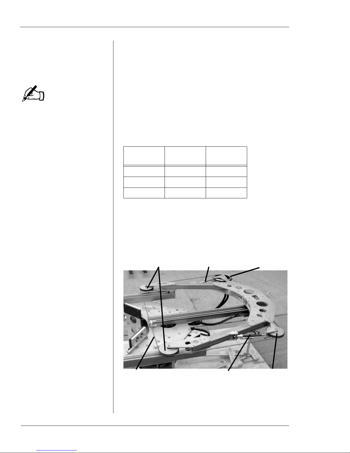
Cutting Wire Drive System
The cutting wire drive system consists of four wheels
mounted on the bow of the machine. Figure 1-1 illustrates
the drive system components.
Figure 1-1. The photo shows the cutting wire drive
system components.
NOTE
Table 1: Subsea Wire Saw Models
Model Min. Pipe
Capacity Max. Pipe
Capacity
WS-3012 12” (305 mm) 30” (762 mm)
WS-3616 16” (406 mm) 36” (914 mm)
WS-5230 30” (762 mm) 52” (1321 mm)
Idler wheels Drive wheel
Tension wheel
Diamond wire
Tensioning knob
Tension spring
Chapter 1, About the Subsea Wire Saw: Equipment Description
E.H. Wachs Part No. 08-051-MAN, Rev. 1-0709 5
The drive wheel is operated by the hydraulic drive motor to
turn the wire around the cutting system loop. It is mounted
on a pivoting fixture used to adjust the tension of the wire.
The tension is set using a knob on the fixture, which also
positions the wheel for installing and removing the cutting
wire.
The tension wheel is on a pivoting, spring-loaded fixture
that maintains wire tension. The other two idler wheels are
fixed at the bottom of the bow where the cutting wire
engages the pipe.
The wire is a custom-made loop for the size of the saw.
Spare wires can be ordered from E.H. Wachs.
Feed System
A feed drive mechanism on the main frame of the machine
drives the bow and cutting system up and down to perform
the cut and retract the bow after cutting. The bow rides on
three feed rails and is driven by a feed screw in the center of
the frame. Figure 1-2 and Figure 1-3 show the main feed
system components.
Figure 1-2. The saw bow moves on three feed rails on
the frame. The feed screw along the center rail drives
the bow.
Feed rails
Saw bow Feed screw

Subsea Wire Saw User’s Manual
6 Part No. 08-051-MAN, Rev. 1-0709 E.H.Wachs
Figure 1-3. The feed system components are shown.
The feed block is attached to the saw bow.
The top of the feed screw has a drive nut to allow the feed to
be operated manually, and a clutch in the top coupling dis-
engages the feed screw if the feed drive jams or reaches the
end of travel.
Figure 1-4. Use the manual feed nut to move the saw
bow if it cannot be operated using hydraulic power.
Turn the nut clockwise to retract the bow away from
the workpiece.
Feed block Feed screw
Feed motor Drive chain
Manual feed nut
Manual
feed nut

Chapter 1, About the Subsea Wire Saw: Equipment Description
E.H. Wachs Part No. 08-051-MAN, Rev. 1-0709 7
The feed system has a self-adjusting speed control feature.
A hydraulic actuator on the tension wheel fixture measures
the deflection of the wire as it cuts. If the feed speed is too
fast, the increased wire deflection trips the actuator, which
slows down the feed rate. This allows the cutting action of
the wire to catch up. At maximum deflection of the wire, the
actuator will stop the feed motion for as long as necessary.
Figure 1-5. The actuator controls the feed rate by
measuring the deflection of the cutting wire.
Clamping System
An adjustable clamping system allows you to configure the
machine for pipe sizes within each model’s range. The two
clamping arms are attached to the main frame with two-
pronged forked pins that are removable to reposition the
arms.
The clamping arms are engaged by hydraulic cylinders
mounted to the frame. When the cylinder rods are extended,
the clamps pivot inward to grip the underside of the pipe
and hold the machine securely to it. Figure 1-6 illustrates
the clamping operation.
See the end of this chapter for drawings that illustrate clamp
position settings for the range of each wire saw model.
Feed control actuator Tension wheelTension spring
Subsea Wire Saw User’s Manual
8 Part No. 08-051-MAN, Rev. 1-0709 E.H.Wachs
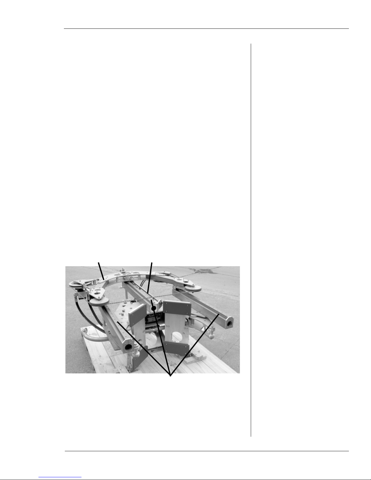
Figure 1-6. The photo shows the wire saw in position
for clamping on a test workpiece. When the hydraulic
cylinder is extended, the clamp arm pivots and closes
on the pipe. Both clamping arms operate together.
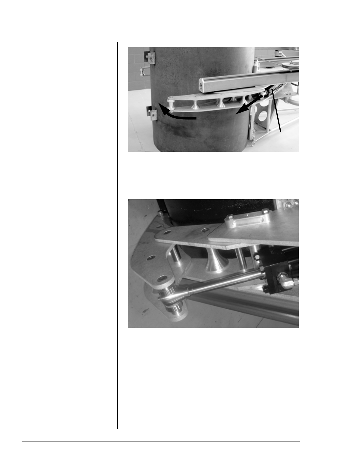
Figure 1-7. The photo shows the clamping cylinder
extended and the clamp arm secured against the pipe.
The frame of the machine has clamp shoes attached that the
machine rests upon when installed on the pipe. These shoes
are made of a compressible composite material that deforms
slightly under pressure to create a secure, slip-free grip on
the pipe when the machine is clamped.
Clamping
cylinder
Clamping
motion
Clamping arm
pivots to con-
tact pipe

Chapter 1, About the Subsea Wire Saw: Equipment Description
E.H. Wachs Part No. 08-051-MAN, Rev. 1-0709 9
Figure 1-8. The front mounting shoes are shown.
Topside Control Panel
Figure 1-9 illustrates the controls used to operate the subsea
wire saw. Chapter 3 includes detailed instructions.
Figure 1-9. The photo shows the controls on the top-
side control unit. (The fourth circuit, to the far right, is
not used with the subsea wire saw.)
Clamp pressure gauges
Clamp
direction
Cutter
speed
Cutter pressure gauge Feed speed Feed pressure gauge
Feed
direction
Clamping flow levers (engage
both at once—shown closed
under pressure)
Feed flow lever
(shown open)
Cutter flow lever
(shown open)
Subsea Wire Saw User’s Manual
10 Part No. 08-051-MAN, Rev. 1-0709 E.H.Wachs
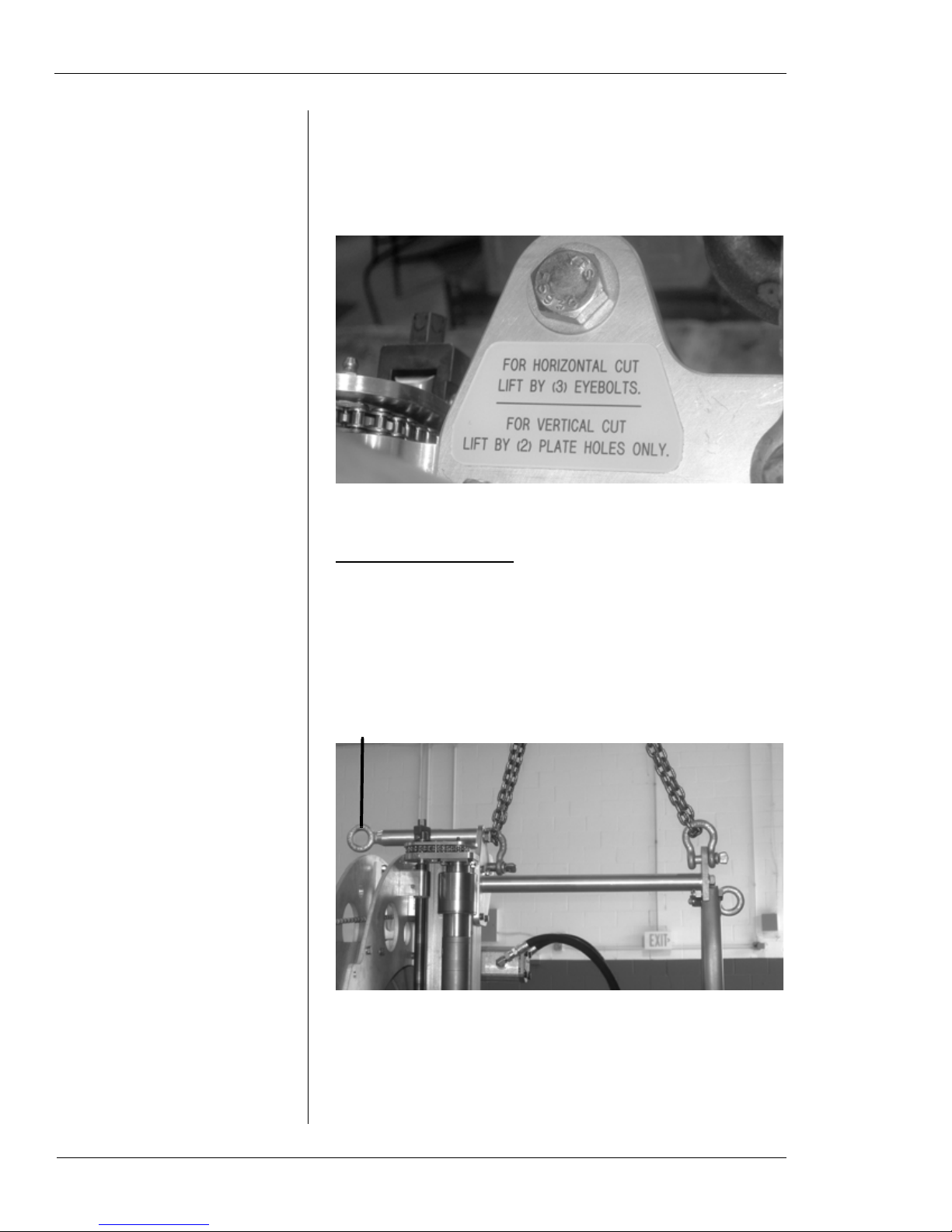
Rigging the Machine
A rigging instruction label is attached to the top of the
machine frame.
Figure 1-10. The rigging label is on top of the frame.
Lifting for Vertical Cut
Attach the machine to the lifting device using chains on the
top lift hooks. Tip the machine up to a vertical position, then
pick it up. Make sure the chains are the appropriate length to
hold the machine reasonably straight.
Figure 1-11. To position the machine vertically on the
pipe, attach to the two top lift hooks.
IMPORTANT: Do not attach to this hook
when lifting the machine vertically!

Chapter 1, About the Subsea Wire Saw: Equipment Description
E.H. Wachs Part No. 08-051-MAN, Rev. 1-0709 11
Lifting for Horizontal Cut
With the machine positioned horizontal on the floor or deck,
attach a lift to the two hooks on the lift bar and the front
hook on top of the frame.
Figure 1-12. To position the machine horizontally on
the pipe, attach to the two lift bar hooks and the front
hook on the top.
Storing the Machine
Store the machine sitting horizontal with the front of it (the
side with the Wachs logo) facing up. For long-term storage,
clean and dry the machine thoroughly, then cover it with a
waterproof cover.
You can leave the wire installed on the machine during stor-
age. Keep a normal amount of tension on the wire to hold it
in place.

Subsea Wire Saw User’s Manual
12 Part No. 08-051-MAN, Rev. 1-0709 E.H.Wachs


Table of contents
Other E.H. Wachs Saw manuals

Popular Saw manuals by other brands

TYROLIT Hydrostress
TYROLIT Hydrostress FSD1274E5 operating instructions

DeWalt
DeWalt DW349R Series Original instructions

Hitachi
Hitachi CB6YI - 10 Inch Tilting Head Bandsaw instruction manual

Ryobi
Ryobi P501 Operator's manual

eXact
eXact PipeCut 220E Operating instruction

Ingersoll-Rand
Ingersoll-Rand SRA010A1 Product information


