E-Plex 805OPM Series User manual

805OPM
Design specifications
• Transient voltage suppression: EN6100-6-1.
• PCB characteristics: UL 94V-0.
• Power distribution: UL 1077 compliant
(except high-voltage dielectric test).
• Load dump tested to ISO 16750-2.
Key features
• 8 channels with outputs capable of up to 15 amps
each (no more than 50 amps continuously for the
module).
• Pairs of channels may be configured to operate in
parallel.
• PWM dimming capability on all channels.
• Input capability on all channels.
• Reverse battery protected.
• Status LEDs for each channel.
• Thermal, short circuit, and programmable overload
protection.
• Local manual override capabilities.
• Designed for motor and high inrush current loads.
• E-Plex LEN value 2.
Introduction
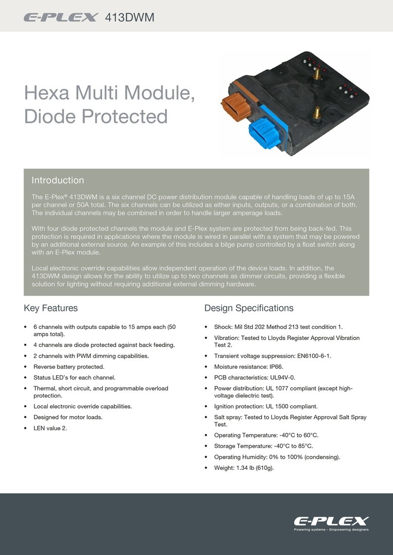
The E-Plex®805OPM is an eight channel DC power distribution module capable of handling loads of up to
15 A per channel or 50 A total. The eight channels can be utilised as either inputs, outputs, or a combination
of both. Output channels may be paired in order to handle larger amperage loads.
The 805OPM incorporates thermal, short circuit, and programmable overload protection in order to
safeguard the module against incorrect wiring or load faults. Manual mode capabilities allow backup
operation of the device loads in the event that the E-Plex system goes offline.
In addition, the 805OPM design allows for the ability to utilise any combination of channels as dimmer
circuits, providing a flexible solution for lighting control.
Octal Power
Module
8 channel DC power distribution module

805OPM
Electrical specifications
NOTES:
1. Module will shut down when voltage reaches 8.5 V and will power back up at 9 V
2. Specified as 50 feet of 2 AWG (43 mm²) wires with a 6 inch diameter spool for both power and ground.
3. Refer to maximum load inductance graph below
Taking the device outside the limits specified above may cause permanent damage to the device.
The supply to the module should be protected by a fuse or circuit breaker of appropriate capacity and no more than a maximum capacity of 50 A.
Trip speed characteristics
Maximum load inductance
Description Minimum Nominal Maximum
Voltage19 VDC – 32 VDC
Current, Total – – 50A
Current, per channel continuous 0 A – 15 A
Short circuit current limit per channel – – 90 A
Input low threshold 0V – 3.5V
Input high threshold 4.5 V – 32V
Lead inductance 0 – 100 µH 2
Load Inductance 30 – 100 mH
PWM Frequency – 120 Hz –

805OPM
Channel status LED (configured as output)
Channel status LED (configured as input)
E-Plex activity LED
Fault LED
LED state Description
Off Channel off
On Channel on
Flashing alone or out of phase with fault LED Channel tripped due to over current
Flashing together with fault LED Channel fault (short circuit or hardware fault)
LED state Description
Off Channel inactive (open circuit)
On Channel active (shorted to ground)
LED state Description
Off No E-Plex active
On E-Plex activity
LED state Description
Off No fault
On Outside of operating conditions
(reverse battery, over temperature, or low battery)
Flashing Channel fault (see above)
Local controls
& indication
1 2 3 4 5 6 7 8 9 10 11 12 13 14 15 16
1
5
2
6
3
7
4
8
Battery
+
Fault / 0
Battery
–
Protect with
50A fuse
or breaker
www.e-plex.co
Address Firmware
Activity / 9 7 - 32 VDC
E-Plex
Activity
CH 1
+ –
CH 2
+ –
CH 3
+ –
CH 4
+ –
CH 5
+ –
CH 6
+ –
CH 7
+ –
CH 8
+ – E-Plex
805OPM
Fault / 0
E-Plex activity / 9
Channel status

805OPM
E-Plex address indication
Manual mode
At power up the module will indicate its E-Plex address by flashing the LEDs. One of the LEDs will flash for 2 seconds, this
indicates the most significant digit of the address. This will be followed by one second with all LEDs off. Then another LED will
flash to indicate the next digit of the address. This pattern will repeat until all 4 digits have been displayed. For example if LED 1
flashes followed by LED 6, then fault (0), then 8, the modules address is 1608.
All LEDs flash repeatedly with the above sequence at power up if the module has not been assigned an address.
Manual mode is a backup mode of operation which is automatically enabled if no commands are received from the main control
unit (clock module). This allows for a minimum level of device control even when there are faults with other parts of the system.
If a module is unprogrammed all channels are disabled.
When the network is inactive there are two parameters that may be configured for output channels; automatic and manual control.
Automatic control
When automatic control is enabled the channel can be set to turn its output on or off when the module enters manual mode.
When disabled the output will remain in the same state as it was in before entering manual mode.
Manual control
The keypad switches may be programmed to override the automatic control with either momentary or latching behaviour.
When the network is active the functionality of the buttons is determined by the system software.
Typical wiring diagram
+–
M
Nav equipment
Toggle switch
Momentary switch
Halogen lighting
Motor
LED lighting
Nut (torque to 3 Nm)
Cable Spring washer
Flat washer
Ring terminal
50 A
Max.
1 2 3 4 5 6 7 8 9 10 11 12 13 14 15 16

805OPM
Washer arrangement
+–
M
Nav equipment
Toggle switch
Momentary switch
Halogen lighting
Motor
LED lighting
Nut (torque to 3 Nm)
Cable Spring washer
Flat washer
Ring terminal
50 A
Max.
1 2 3 4 5 6 7 8 9 10 11 12 13 14 15 16
Wiring specifications
Pin # Pin Description
1 Input / Output +VE CH 1
2 CH 1 Return -VE
3 Input / Output +VE CH 2
4 CH 2 Return -VE
5 Input / Output +VE CH 3
6 CH 3 Return -VE
7 Input / Output +VE CH 4
8 CH 4 Return -VE
Pin # Pin Description
9 Input / Output +VE CH 5
10 CH 5 Return -VE
11 Input / Output +VE CH 6
12 CH 6 Return -VE
13 Input / Output +VE CH 7
14 CH 7 Return -VE
15 Input / Output +VE CH 8
16 CH 8 Return -VE
All outputs are PWM capable and may be used to dim halogen and LED lighting loads.
Please Note: - LED Lighting modules must support PWM Dimming or incorrect operation may occur.
Reversed Battery Conditions:
To effectively protect both the connected device and the Module, the power supply to the module input must be protected by 50A
over current protection device. If the module is powered up with the polarity reversed the supply breaker or upstream fuse will
trip, but loads will be protected.
1 2 3 4 5 6 7 8 9 10 11 12 13 14 15 16
1
5
2
6
3
7
4
8
Battery
+
Fault / 0
Battery
–
Protect with
50A fuse
or breaker
www.e-plex.co
Address Firmware
Activity / 9 7 - 32 VDC
E-Plex
Activity
CH 1
+ –
CH 2
+ –
CH 3
+ –
CH 4
+ –
CH 5
+ –
CH 6
+ –
CH 7
+ –
CH 8
+ – E-Plex
805OPM
The warranty may be voided if powered up with reversed battery connections
and with incorrectly rated upstream protection.

805OPM
Cable sizing
For Power / Battery Connections
Must be protected at a maximum of 50 A. Maximum wire size should be sized based on upstream fuse capacity. When
connecting the power source to the power studs on the module, the M5 hex nuts should be torqued to 3 Nm (22 in lb) after
installing the battery terminals to the studs. Failure to properly torque hex nuts may result damage to the unit and intermittent
operation due to terminals loosening over time.
When using a single conductor, a 35 mm² cable with a typical ring terminal thickness can be used. When using two conductors,
25 mm² cable with typical ring terminal thickness can be used. At least one turn of thread must be visible over the nut after
tightening. It is important not to fit a washer below the ring terminal as the increased resistance will cause heating and damage to
the module and cabling.
Parallel Operation
When connecting channels in parallel, it is important to match the resistance of the wires from each channel. If the wires are not
balanced, one will carry more current than the other, which may result in the channel tripping prematurely.
The best way to ensure that the wires are matched is to join them as close to the module a possible using wires of equal length
and cross sectional area. This should be 4 mm² (14 AWG) wire, no longer than 100 mm (4”). E-Plex Ltd. can supply a pre-made
assembly for this purpose. See below for the ordering code.
Loads with multiple supplies
When a channel is used to power a load, it is necessary to fit a back feed prevention diode to protect against equipment damage
when the OPM channel is off but the other channel is on. E-Plex Ltd. can supply a back feed diode with integral resister which will
protect against back feeding whilst still allowing feedback to be monitored. See below for the ordering code.

805OPM
Dimensions
Mounting instructions
Screw assembly to a flat mounting surface in two places, as shown in the illustration labels A and B. Use M4 size panhead screw,
M4 split lock washer and M4 washer or No. 6 wood screw Torque to 250~280 N-cm. Do not exceed this torque as it could cause
damage to the enclosure.
183mm [7.2"]
119.5mm [4.7"]52.2mm [2.1"]
224.4mm [8.8"]
171.1mm [6.7"]
64.5mm [2.5"]
55.1 [2.2"]
4.2mm [0.17"] for M4
fixings or no.6 woodscrews
48.1mm [1.9"]
63.2mm [ 63.2"]

805OPM
The 805OPM device can be supplied as a retro fit module and will have the relevant firmware personality for the older module it is
replacing.
These modules are the 366HMM, 407QHM, 413DWM4when ordered (see part number below) they will require the relevant
adapter cable to allow it to be connected to the original wiring. Due to the size of the 805OPM module vs the older modules a
diagram showing module and cable space requirements is shown below.
The personality in the 805OPM module makes the system believe that the original module type is connected and the programming
and responses will be the same.
For information on specification changes and connections an additional information sheet is available and provided with the
supplied module.
NOTES:
3It is not recommended to use emulated devices for new installs and only as necessary for retrofits.
We would always recommend using the native 805OPM for future compatibility and upgradability.
4When emulating a 413DWM, additional external diodes may be required, depending on application. If in doubt, please contact your local dealer.
805OPM Retrofit and personalities3
Mechanical specifications
Description Specifications
Front Bezel Material Aluminum
Back Case Material ABS
IP Rating IP 20
Operating Temperature ¹ -20ºC - 6ºC (-4ºF - 140ºF)
Storage Temperature -30ºC - 85ºC (-22ºF - 185ºF)
Operating Humidity 5% to 95% (Non Condensing)
Weight 541g (5.25oz)
Overall Length 183 mm (7.21”)
Overall Height 63 mm (2.50”)
Overall Depth (including Cable) 224 mm (8.8”)
Mounting Hole Size M4
Power Connecting Stud Size M5
NOTES:
1. Outputs shut down at 80ºC and come back on at 75ºC.

805OPM
Dimensioned Drawing with retro fit cable fitted
183mm [7.2"]
171.1mm [6.7"]
119.5mm [ 4.7"]52.2mm [2.1"]
224.4mm [8.8"]
48.1mm [1.9"]
63.2mm [ 63.2"]
64.5mm [2.5"]
55.1 [2.2"]

805OPM
Ordering codes
When used as emulated device type
Description Old Code New Code
805OPM Series - Octal Power Module EP3-SW-IO-8CH-805OPM-C3 EP3-805OPM-C3
Connector - 1 to 8 CO-CONN-805OPM-PLUG1 CO-CONN-805OPM-PLUG1
Connector - 9 to 16 CO-CONN-805OPM-PLUG2 CO-CONN-805OPM-PLUG2
Back feed blocking diode EP-MISC-821BD EP-MISC-821BD
0.5 Metre EP3 Cable EP3-CA-0.5M EP3-CA-P/P-00.5
Description Old Code New Code
805OPM with 336HMM Personality EP3-SW-IO-6CH-366HMM-REV O EP3-366HMM-REV O
336HMM Personality cable EP3-CA-HOI EP3-CA-HOI
805OPM with 407QHM Personality EP3-SW-IO-6CH-407QHM-REV O EP3-407QHM-REV O
470QHM Personality cable EP3-CA-QOI EP3-CA-QOI
805OPM with 413DWM Personality EP3-SW-IO-6CH-414DWM-REV O EP3-414DWM-REV O
413DWM Personality cable EP3-CA-HOI EP3-CA-HOI

52 – 54 Riverside, Sir Thomas Longley Road, Medway City Estate, Rochester,
Kent ME2 4DP
tel: +44 (0)1634 711622
email: [email protected]
web: www.e-plex.co.uk
Important Notice: E-Plex Ltd. (E-Plex) reserves the right to make changes to or discontinue any product or service identified in this publication without notice. E-Plex advises its customers to obtain
the latest version of the relevant information to verify, before placing any orders, that the information being relied upon is current. E-Plex assumes no responsibility for infringement of patents or
rights of others based on E-Plex applications assistance or product specifications since E-Plex does not possess full access concerning the use or application of customers’ products. E-Plex also
assumes no responsibility for customers’ product designs.
805OPM Version 1.0 | AUG 2018
This manual suits for next models
4
Table of contents
Other E-Plex Control Unit manuals