Gefen GEFENTV-SIGGEN User manual

Gefen TV Signal
Generator
USER MANUAL
www.gefen.com

Technical Support:
Telephone (818) 772-9100
(800) 545-6900
Fax (818) 772-9120
Technical Support Hours:
8:00 AM to 5:00 PM Monday thru Friday.
Write To:
Gefen, Inc.
c/o Customer Service
20600 Nordhoff Street
Chatsworth, CA 91311
www.gefen.com
Notice
Gefen Inc. reserves the right to make changes in the hardware, packaging and
any accompanying documentation without prior written notice.
The Gefen TV Signal Generator is a trademark of Gefen Inc.
© 2007 Gefen Inc., All Rights Reserved
ASKING FOR ASSISTANCE

TABLE OF CONTENTS
Introduction / Operation Notes
Features
Panel Layout
Panel Layout Continued
Basic Operation
LCD Layout / Timing Table
Pattern Table
Pattern Table Continued
RS-232 Remote Control Application
RS-232 - Timing
RS-232 - Pattern
RS-232 - Pattern Timing/Pattern
Specications
Warranty
1
2
3
4
5
7
8
9
10
11
12
13
14
15
16

INTRODUCTION
Thank you for purchasing the Gefen TV Signal Generator.
The Gefen TV Signal Generator offers a long list of advanced features. It provides
still and moving test patterns in SD and HD formats. It will also output audio
tone in 2, 4, 6, and 8 channel over HDMI. There’s also a test that will output
an HDCP encrypted signal to test HDCP-compliancy. Best of all, the Gefen TV
Signal Generator is portable, cost effective, and is a useful tool that allows video
professionals to calibrate and test video equipment and displays.
1
OPERATION NOTES
READ THESE NOTES BEFORE INSTALLING
OR OPERATING THE HOME THEATER SCALER
• Gefen TV Signal Generator will work with all HDMI and DVI displays.
• Please download the RS-232 program from the download section of Gefen’s
website at: http://www.gefen.com/kvm/support/download.jsp

FEATURES
• HDMI v1.2, HDCP 1.1 and DVI 1.0 compliant
• Multi-format output for HD and SD video
• Still and moving test patterns
• Supports HDCP signal verication pattern (P39)
• Supports multi-channel audio testing.
• Portable size design
• Over 35 Still & Motion Patterns
• Internal HDMI & External Digital & Analog audio connectors
• RGB & YUV Color Spaces Supported
• PC & HDTV Timings Supported
• PAL & NTSC frame rates
• On-panel LED display and LED indicators
• Remote control
• Supports RS-232 control
• PC software application is downloadable at:
http://www.gefen.com/kvm/support/download.jsp
INCLUDES:
(1) Gefen TV Signal Generator
(1) 6ft HDMI cable (M-M)
(1) 5v DC Power Supply
(1) User’s Manual
2

PANEL LAYOUT
Back
Front
3
RS-232
Port
IR receiver
(optional)
HDMI
Output
Optical
Input
Analog
Input
Overscan
5V DC
Input
Main Power
Switch
NOTE:
1. OVERSCAN Button
By default the Gefen TV Signal Generator is set to underscan mode. If your
video signal does not ll the entire display, press this button once to switch
to overscan mode. You can press the button a second time to revert to
underscan mode.
2. HDMI OUT
The HDMI output can be connected to an HDMI display using HDMI cable or
to a DVI display using HDMI to DVI cable or Gefen adapter from HDMI to DVI.
3. RS232 Communication Port
Connect to the COM1 or COM2 port of your PC to control the unit remotely
using the appropriate application.

PANEL LAYOUT CONTINUED
Diagram 1
4
External Audio Analog Indicator
External Audio Optical Indicator YUV 4:2:2 Color Space Indicator
YUV 4:4:4 Color Space Indicator
RGB 4:4:4 Color Space Indicator
Auto Mode Indicator
External Audio HDMI Indicator
HDMI Signal Output
DVI Signal Output
Audio
Selector
Timing
Selector UP
Timing
Selector DOWN
Output
Signal
Selector
LCD Display
Auto
Mode
Selector
Pattern
Selector UP
Pattern
Selector DOWN
Color Space
Selector

BASIC OPERATION
5
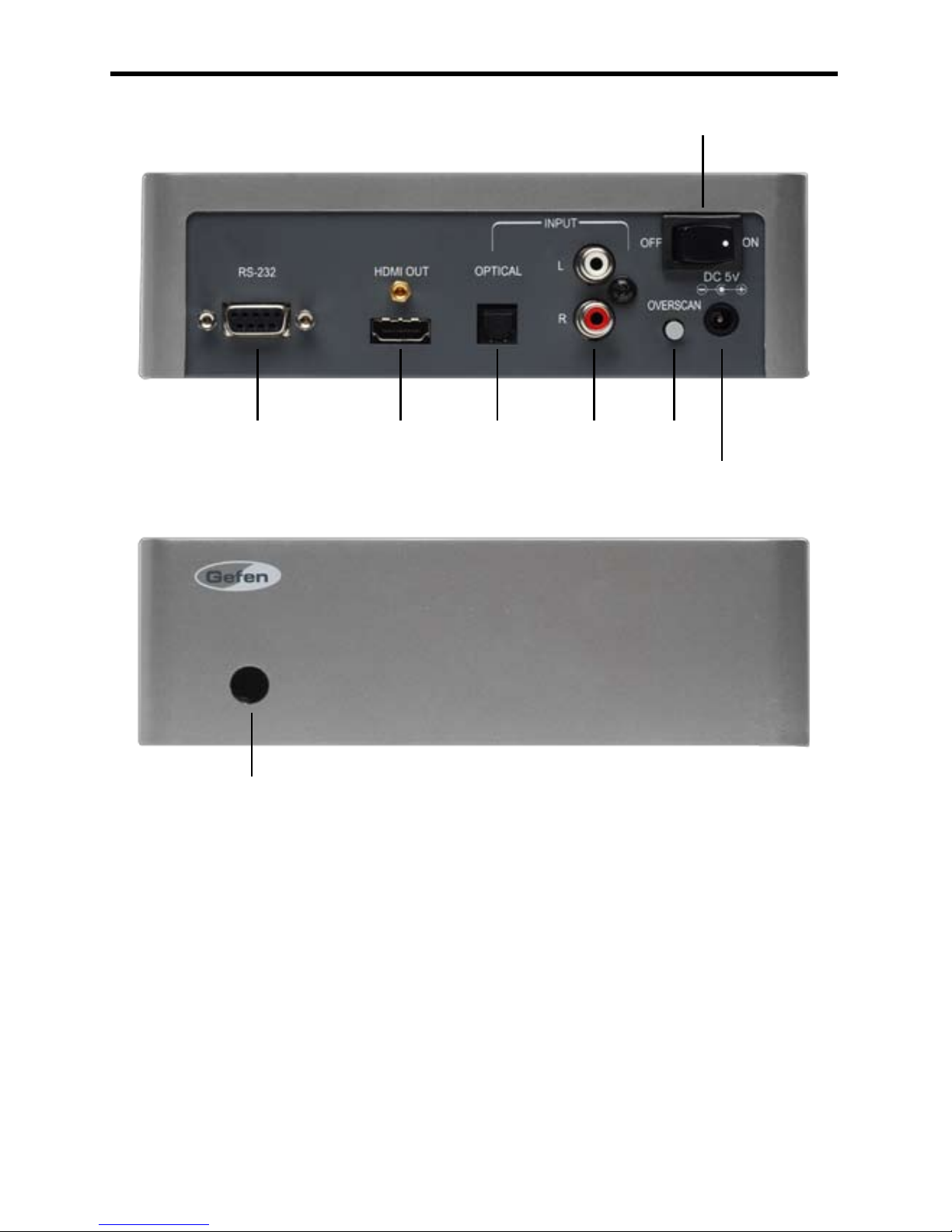
How to connect the Gefen TV Signal Generator
• Connect the HDMI OUT of the Gefen Signal Generator to the HDMI of
you HDMI display or device
• Plug the 5V power supply into the Gefen TV Signal Generator
• Turn on the display rst.
• Turn on the Gefen TV Signal Generator second
You should now be receiving a default signal from the Gefen TV Signal
Generator.
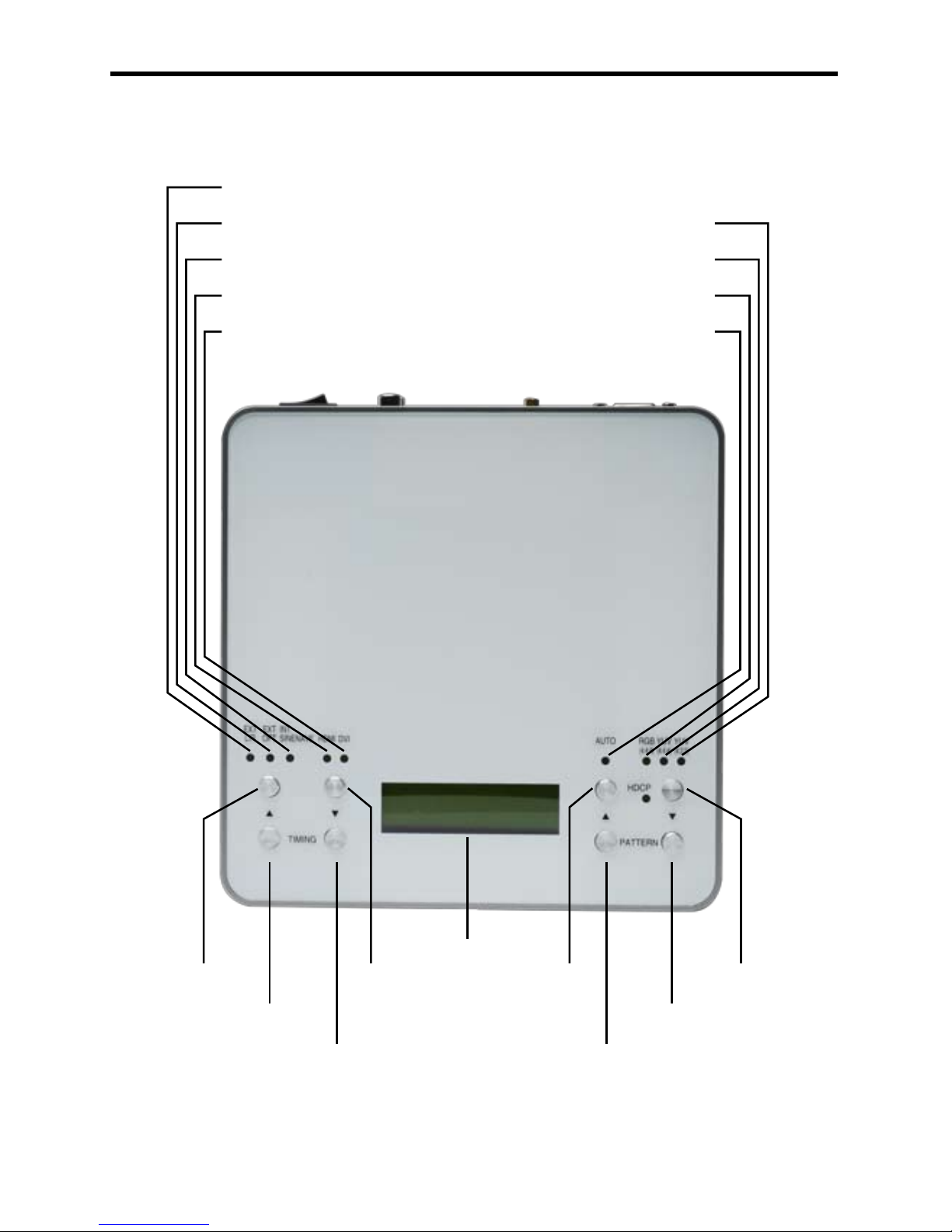
You may need to press the OVERSCAN button if the signal from the Gefen TV
Signal Generator does not ll the entire screen.
If you are not receiving a picture, check your power supply. Make sure the
Gefen TV Signal Generator is plugged in and that the unit is turned on. If your
display has more than one HDMI port, make sure that your display is set up
to receive signals from that port #. If you’re testing HDMI, make sure that the
Output Signal Selector is set to HDMI.
If you are still unable to receive a picture, it is possible that the current output
timing is not supported by your monitor. The current timing (resolution and
refresh rate) are displayed in the LCD window on the unit. Use the Timing
Selector UP or DOWN buttons to select a different timing. See chart on page
7.
Once you have established a timing that is accepted by your display, you can
select from a wide array of video test patterns by using the Pattern Selector UP
or DOWN buttons (see table beginning on page 8).
Checking stereo or multi-channel audio capability
• Connect the HDMI OUT to the HDMI IN of your A/V receiver (if
applicable).
• Connect the HDMI OUT of the Gefen TV Signal Generator to the
HDMI IN of your A/V receiver.
• Connect the HDMI OUT from the A/V receiver to the HDMI IN of your
display.
• Set the Audio Output Selector to INT SINEWAVE.
• Use the Pattern Selector buttons to select P38 AUDIO and follow the
on-screen directions.
The audio test is capable of verifying 2, 4, 6 and 8 discrete channel audio.

BASIC OPERATION
6
External Audio Inputs
In addition to using the internal sinewave for checking audio, the Gefen TV
Signal Generator allows you to use your own audio source and accepts both
analog and digital audio signals. For digital audio connections, connect an
optical cable from your audio source to the OPTICAL input on the back of the
unit and select EXT OPT by pressing the Audio Selector button. For analog
connections, connect a stereo RCA cable to your audio source and plug the
other end into the Analog Input jacks and select EXT L/R by pressing the Audio
Selector button. To prevent a reversed stereo image, make sure that the left
and right channels are connected properly.
Testing DVI
You can test DVI devices by setting the Output Signal Selector to DVI. This
button will toggle between HDMI and DVI color space. Simply connect the
HDMI OUT from the Gefen TV Signal Generator to the DVI IN of the device
you wish to test.
Color Space
You can switch color spaces by pressing the Color Space Selector button.
Pressing this button will cycle through RGB, YUV2 and YUV4 color spaces.
HDMI supports all color spaces but DVI only supports YUV2.
HDCP compliance
To check HDCP compliance, select a timing that is accepted by your display
and use the Pattern Selector buttons to select P39 HDCP-Produce from the list
of patterns.
You can also check audio in this mode by setting the Audio Output Selector to
INT SINEWAVE.
HDCP testing can only be veried through HDMI or DVI connections.
Automatic Testing
The Gefen TV Signal Generator has the capability to auto select specic
timings from the table provided on page 7.
Press the AUTO button to start auto mode. To stop the auto mode, press the
AUTO button again.
.

TIMING TABLE
LCD LAYOUT
7
No. Resolution Hz No. Resolution Hz
T01 640x480 60 T19 1600x1200 60
T02 640x480 72 T20 1920x1200 60
T03 640x480 75 T21 720x480i 59
T04 640x480 85 T22 720x480i 60
T05 800x600 56 T23 720x480p 59
T06 800x600 60 T24 720x480p 60
T07 800x600 72 T25 1280x720p 59
T08 800x600 75 T26 1280x720p 60
T09 800x600 85 T27 1920x1080i 59
T10 1024x768 60 T28 1920x1080i 60
T11 1024x768 70 T29 1920x1080p 59
T12 1024x768 75 T30 1920x1080p 60
T13 1024x768 85 T31 720x576i 50
T14 1280x960 60 T32 720x576p 50
T15 1280x960 85 T33 1280x720p 50
T16 1280x1024 60 T34 1920x1080i 50
T17 1280x1024 75 T35 1920x1080p 50
T18 1280x1024 85
Timing Number
Pattern Number
Pattern Description
Timing Resolution Timing Frequency (Hz)

PATTERN TABLE
8
No. Name Description Application
P01 White
Purity Pattern
White (100% Y)
3 primary colors:
Red, Green, Blue
4 Additional colors:
Magenta, Yellow,
Cyan and Black
- Brightness control
- Purity checks and adjustment
- Interference between sound
and chroma carrier
- Color A.G.C.
- Chroma writing current of
video recorders
- White setting
- Synchronization
- FM demodulator (white level)
- Beam current of picture tube
- Luminance writing current
P02 Blue
P03 Red
P04 Magenta
P05 Green
P06 Cyan
P07 Yellow
P08 Black
P09 Grad-Red
Gradual Pattern
Gradual transition of
colors
- Brightness control
- Luminance writing current
- Linearity of video amplier
- Overall color performance
- Amplitude response resolution
- Linearity of chroma amplitude
P10 Grad-Green
P11 Grad-Blue
P12 Grad-Gray
P13 Color Bar
Color Bar
8 vertical bars:
White, Yellow, Cyan,
Green, Magenta,
Red, Blue and Black
- Overall color performance
- Burst keying
- Subcarrier regeneration
- Matrix circuit check
- RGB ampliers
- Color delay versus B/W
signal saturation
P14 Gray -8
Grayscale
Full screen linear
staircase signal to
white
Steps:
8/16/32/64/256
- Brightness + contrast circuitry
- Grayscale tracking
- Linearity of video amplier
P15 Gray-16
P16 Gray-32
P17 Gray-64
P18 Gray-256
P19
V-Line On/
Off
Black White
Vertical
Full screen linear
vertical bar signal
with black/white
intervals of 1 and 12
pixels
- Check bandwidth and phase
behavior of a video
transmission
- Verify video amplier
- Verify color temperature
P20
BW-12

No. Name Description Application
P21
H-Line On/
Off
Black-White
Horizontal
Full screen linear
Horizontal bar
signal black/white
intervals of 1/3/6
pixels
- Check bandwidth and phase
behavior of a video transmission
- Verify video amplier
- Verify color temperature
P22
Hor-3
P23
Hor-6
P24
Multi-burst
Multi-burst
Full screen
denition pattern
of frequencies
0.5, 1.0, 2.0,
4.0, 4.8, and 5.8
MHz for 625 line
systems
- Video bandwidth
- Check luminance amplier in B/W
- Amplitude response resolution
- Check resolution of monitors
and video recorders
P25
Pludge
Pluge Pattern
Three vertical bar
pluge pulses and
3 horizontal pluge
pulse boxes
- Calibrate black level
- Calibrate black levels: super-
black, normal-black and near-black
P26
Grid-1
Grid
Full screen grid
with black/white
intervals of 1 and
6 pixels
- Static convergence
- Dynamic convergence
- Pin-cushion correction
- E/W-N/S corrections
- Amplitude response
P27
Grid-36
P28
Gra-256-R
Gradient
Full screen linear
256 step staircase
signal from black
to red, green, or
blue
- Brightness + contrast circuitry
- Linearity of video amplier
P29
Gra-256-G
P30
Gra-256-B
P31
Circles
Circles
Black circle on
white background,
640x480 has 4 by
3 total 12 circles,
800x600 has 5 by
3 total 15 circles,
and 1024x768
has 6 by 4 total
24 circles
- Overall linearity
- Overall geometry
- Framing
- Reections
9
PATTERN TABLE CONTINUED

No. Name Description Application
P32 BW_UD
Black and White
Up/Down
Full screen lled
with upper half of
100% white and
lower half of 100%
black
- Brightness control
- Purity checks and adjustment
- White setting
- Synchronization
P33 Gefen-1
Gefen Patterns
Gefen specically
designed patterns
- Multiple purpose
P34 Gefen-2
P35 Gefen-3
P36 Gefen-4
P37 Crosshatch
Crosshatch
Vertical and
horizontal hatch
pattern. White lines
on a black
- Multiple point color
convergence
- Overall geometry, rotation,
and overscan
P38 Audio
Audio
PCM sine wave
tone sent to either
the analog, optical,
or internal HDMI
output. 2, 4, 6, or 8
channel
- Multi-channel audio
compatibility
P39 HDCP
HDCP-Produce
Green/Blue
horizontal bars
with HDCP
verication and data
comparison on the
upper rst third area
of black background
- HDCP verication
- HDCP data comparison
- HDCP authentication check
- HDCP transmitting encrypted
data check
10
PATTERN TABLE CONTINUED

RS-232 REMOTE CONTROL APPLICATION
1. Main Window
Double-click the executable le to launch the remote control application. The
main window will show up. Click the Connect button to link to the unit.
2. Select COM port to control
The application will prompt you to select which COM port connected to the unit
you want to control. Select from COM1 or COM2 and click OK.
Pin Denition Pin Denition
1 NC 1 NC
2 TxD 2 RxD
3 RxD 3 TxD
4 NC 4 NC
5 GND 5 GND
6 NC 6 NC
7 NC 7 NC
8 NC 8 NC
9 NC 9 NC
11
The RS-232 program can be downloaded from the download section of
Gefen’s website at: http://www.gefen.com/kvm/support/download.jsp

Click on the TIMING button to launch the TIMING selection window. Click
“Show List” button to select from TIMING list and adjust the Horizontal/Vertical/
Pixel Clock settings, when complete, click “Run Timing” button to start the
output of selected timing (resolution/frequency.)
List of Timings
RS-232 - TIMING
12

RS-232 - PATTERN
Click the PATTERN button to launch the PATTERN selection window. Click
“Show List” button to select from TIMING list and adjust the Horizontal/Vertical/
Pixel Clock settings, when complete, click “Run Timing” button to start the
output of selected timing (resolution/frequency.)
List of Patterns
13

14
Click and select the “Program” from “Edit” option of the tool bar to launch the
Program window.
Program the desired sequence of timing/pattern/unit/show time, then click
“Upload” to send the program to the unit.
Click and select the “Save as” from “File” option of the tool bar to save your
program. You click the “Open” from “File” option of the tool bar later on to load
your saved program.
RS-232 - PROGRAMMING TIMING/PATTERN

Single Link Video Bandwidth……..……….....…………………………….165 MHz
Audio Input……………………………………..…………TOSlink, Left / Right RCA
Video Output………………………………………………HDMI (type A connector)
Power Supply…………….……………..5V DC 3.2A power supply (AC 90-240V)
Weight………………………………………………………......................…..1.5 lbs
Dimensions………………………………………………........11” W x 5” D x 1¾” H
RS-232…………………………………………………………..............DB-9 type C
Off / On switch………………………………......................………………….Power
Overscan button…………………………………………......................……..Toggle
I/R receiver………………………………………………….. Remote control option
SIGNAL GENERATOR SPECIFICATIONS
15
Table of contents
Other Gefen Inverter manuals