E.T. Systems Challenger MKIII User guide

INSTALLER’S MANUAL
REVISED DATE: March 2004
AUTOMATIC GARAGE DOOR OPENER
take control of your world
2
1. WHAT’S IN THE BOX
A list of contents you will receive with this product and
technical specifications
2. WHAT’S NOT IN THE BOX
A list of optional accessories available for this product.
Please contact your E.T supplier for more information.
3. RECOMMENDED TOOLS
A list of tools recommended for the installation of this
product
4. IMPORTANT: BEFORE INSTALLING
What you need to know before installing this product.
PLEASE ENSURE THAT YOU READ AND UNDERSTAND THIS SECTION BEFORE
INSTALLING THE PRODUCT.
This section highlights any special warnings and precautions.
5. INSTALLING THE HARDWARE
6. WIRING & SCHEMATICS
7. PROGRAMMING & COMMISSIONING
8. MAINTENANCE
9. TROUBLESHOOTING
10. WARRANTY
11. NOTES
Documented serial number and date of purchase
INDEX
6
7
9
17
20
23
24
29
5
3
30

3
MOTORHEAD:
· 1 x Motorhead - complete
· 1 x installer’s manual
· 1 x user’s manual
In sealed bag:
· 4 x M6 x 75mm hexagonal bolts
· 4 x 6mm washers
· 1 x M8 Rawl bolt
· 4 x M8 x 40mm coachscrews
· 1 x M8 x 90mm hexagonal bolt
· 7 x M8 Nylock nuts
· 4 x M8 x 16mm hexagonal bolts
· 2 x M8 x 25mm hexagonal bolts
· 1 x wall mount bracket
· 1 x door bracket
· 4 x No.4 3mm x 16mm counter-sunk self-tapping screws (possie-
drive head)
· 1 x emergency manual release cord kit
· short strip double-sided velcro (for fixing TX to wall for wall console)
DRAWBAR:
· 1 x drawbar complete (see technical specifications overleaf for
more details)
· 2.5 lengths perforated angle hanging straps
· 1 x link arm
· 2 x magnets and holders for chain
WHAT’S IN THE BOX

4
TECHNICAL SPECIFICATIONS
Motor - 220v AC 50Hz
- 2 Amp single-phase
- Thermal overload protection
- Intermittent duty cycle
Drive assembly - Worm reduction gearbox
- Sprocket and chain driven
Traveling speed: - 8.6 metres/ minute (approx.)
Operating temperature: - 0°C – 50°C
Control system: - Microprocessor controlled
- On-board 2-channel receiver with
remote holiday lock-out option.
- Revolution counter load sensing.
Required front-end - Sectional overhead doors:
spacing above door: 50mm above highest point of travel
- Trackless one-piece doors (tip-up):
275mm top edge of closed door
Drawbar options: - 2m: Standard door with 7 foot hinge
- 2.5m: Oversize door with 8 or 9 foot hinge
- 3m: Sesco door up to H 2.3
- 3.5m: Sesco door 2.3 - 2.7m
WHAT’S IN THE BOX

5
· 1, 2 or 3 button transmitters (remote controls)
· Escape lock (to use when no side entrance to garage)
· Extendable link arm (to use when motor installation above
door not possible. Please ask for advice before attempting to
fit these)
· Safety infra-red beams or other safety input device
· Multi-memory location receiver for individual coding security
· Assortment of nuts, bolts, wall plugs, Rawl bolts, coachscrews,
pop-rivets, dowels, self-drilling screws or chemical fasteners
needed for fixing of operator to non-wooden doors and
hanging structures.
PLEASE CONTACT YOUR E.T. PRODUCT SUPPLIER FOR MORE
INFORMATION OR TO ORDER THE ABOVE.
WHAT’S NOT IN THE BOX

6
RECOMMENDED TOOLS
· electric hammer-action drill
· 13mm masonry bit
· 5mm wood bit
· 10mm spanner/ wrench
· 2 x 13mm spanners/ wrenches
· 2.5mm blade flat screwdriver
· PH01 star screwdriver
· hacksaw
· hammer
· 6ft/ 2m A-frame self-standing stepladder
· tape measure
· spirit level
In the case of a non-wooden door, always check with the door supplier
as to recommended fixings and types of tools needed for the installa-
tion of a garge door operator on their doors.

7
BEFORE INSTALLING
BEFORE ATTEMPTING TO INSTALL A GARAGE DOOR
OPERATOR, PLEASE BE CERTAIN YOU HAVE READ AND
UNDERSTOOD THE FOLLOWING:
1. CHECK THAT THE GARAGE DOOR IS MECHANICALLY SOUND AS PER
MANUFACTURERS SPECIFICATIONS.
Points to inspect (general to all makes of doors):
· Mechanisms must be secure, sound, lubricated. Door hinging and
balancing mechanisms must be fastened properly to both door and
structure.
· All nuts and bolts must be tightened according to manufacturers
specifications.
· Do not attempt to adjust tensioning systems unless duly
qualified to do so.
· Ensure springs are not over-stretched and are functioning properly.
· Test door for ease of operation with no snags throughout
door’s travel to full opening to full closing positions.
2. ENSURE THAT A SOLID FIXING POINT IS USED ABOVE DOOR for
securing the front-end bracket. A correctly fabricated bracket
extended from a solid structure is to be used in the case of
fascias, false panelling, header panels etc. For installations
in block walls (cinder bricks), you should use a through-bolt
or cross-braced plate.
3. ENSURE THAT THE HANGING BRACKETS USED TO SECURE THE
MOTORHEAD are fixed to a structure that can support the
weight and load of the garage door operator in operation.
(Rhino boarding and ceiling board DO NOT qualify as solid
structures).

8
4. INSPECT THE SPINE (TOP EDGE) OF THE DOOR for weaknesses such as
cracks or wood-knots. Ensure that the point that the door mount
bracket is attached to, will sufficiently support the weight and load
of the door when operated.
If there is any question to the above, replace or brace the spine
(top edge) of the door with stronger material.
5. ENSURE THAT ANY MECHANICAL LOCKS are either removed or se-
curely locked in the UNLOCKED position.
6. ONE CHALLENGER DOOR OPERATOR IS NOT INTENDED TO BE USED TO
OPERATE TWO SINGLE GARAGE DOORS IN TANDEM. i.e. one motor
per installed door.
E.T. Systems will not guarentee any Challenger unit working on
more than one door. However, the Challenger units will be able to
automate one complete double oversized door.
7. PLEASE BE SURE TO MATCH THE DRAWBAR LENGTH to the type of
hinge assembly when automating oversized doors.
8. Please note that the Challenger range of garage door operators
are NOT IP55 weather-proof rated and are thus only intended for
installations in protected garage-type conditions i.e. under a roof
and out of the wind. This is even more critical when the unit is used
near a coastline.
BEFORE INSTALLING

9
INSTALLING THE HARDWARE
Before starting your installation, check that you have the correct
tools required for your type of installation.
Check that your Challenger garage door operator kit is complete.
STEP 1 - ASSEMBLE THE DRAWBAR TO THE MOTORHEAD
If you choose to mount the
motorhead above the drawbar
(for more headroom when using
the Challenger operator on a Tip
Up type Door), you must reverse
the motor’s forward and reverse
wiring and open and close limits.
BROWN
WHITE
RED
BLUE
FINAL WIRING CONFIGURATION FOR REVERSE MOUNTING
Remove magnet assembly and re-attach
the assembly to the chain by turning it
over so that it ends up as shown in this
photograph.
The magnet should be between the
chain and reed switch.
Once you have finished assembling your Challenger garage door operator,
proceed to Step 2 - Mounting the link arm and door mount bracket.
Figure 9.2
Figure 9.1
Figure 9.3
Using the 4 M6 x 75mm hexagonal bolts
and 6mm washers, tighten your
motorhead unit to the drawbar’s
geared and splined back-end, by
means of the 10mm spanner/ wrench.
10
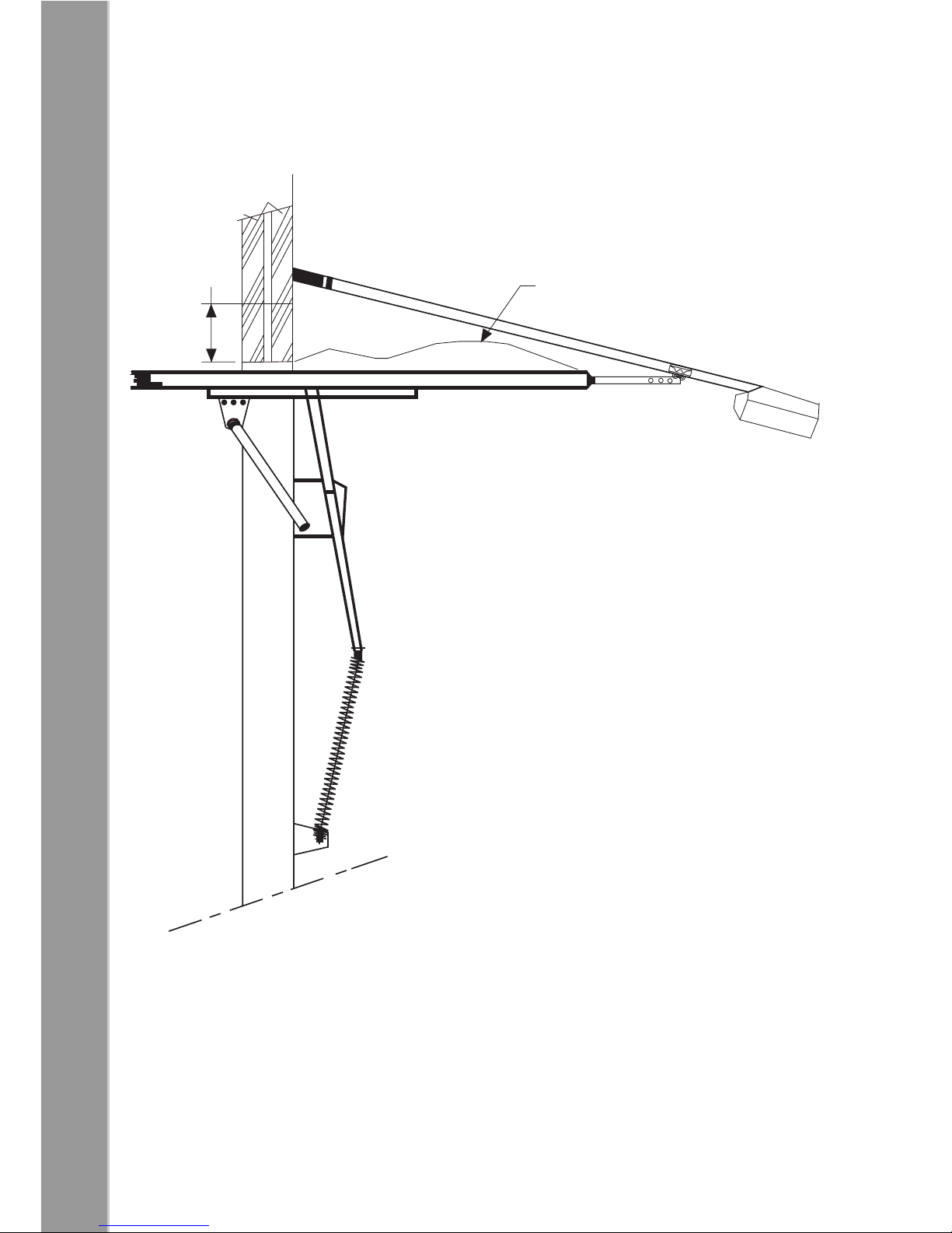
TIP-UP TYPE DOORS
INSTALLING THE HARDWARE
Figure 10.1
275mm
from top of door
when closed
HIGHEST POINT
OF TRAVEL

11
INSTALLING THE HARDWARE
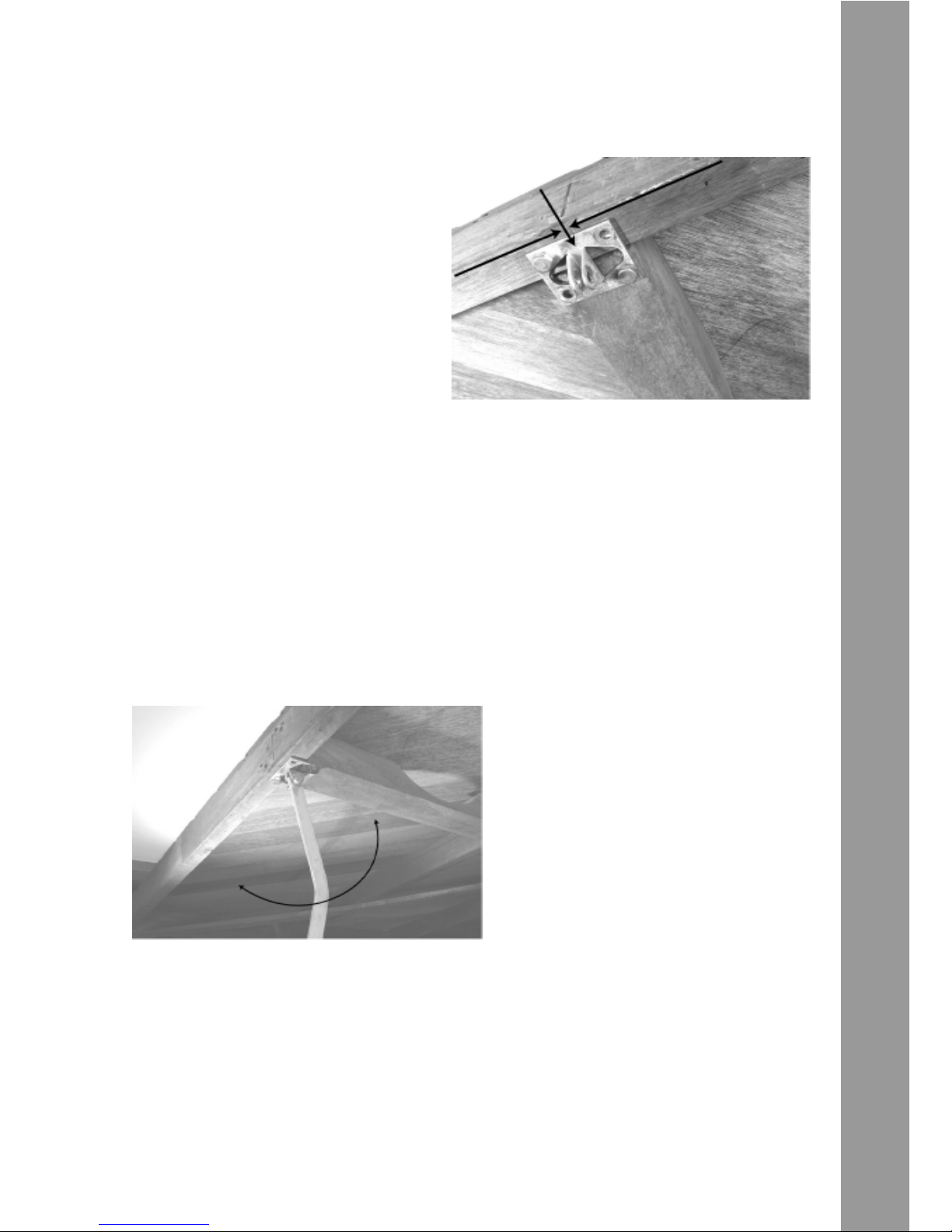
STEP 2 - MOUNTING THE LINK ARM AND DOOR MOUNT BRACKET
TIP UP TYPE DOOR
(refer to diagram on page 10)
Locate and mark the center position
of the spine (top edge) of the door.
Figure 11.1 .
While holding the door mount bracket in place on the centre position, mark
the mounting hole positions.
Using your 5mm wood drill bit, drill pilot holes into the door spine where you
have just marked the door.
Fasten the door mount bracket to
the door, using your 13mm spanners
and/ or wrenches and 2 of the M8 x
40mm coachscrews (for other types of
doors, use recommended fixtures).
Figure 11.2
Fasten the link arm to the door mount bracket, using your 13mm spanners
and/or wrenches and 1 of the M8 x 25mm hexagonal bolts and M8 Nylock
nuts.
Be certain not to over tighten the nut and bolt as the link arm must be able to
swing freely up and down in the door-mount bracket.
When you have completed the above, move on to Step 3 - Determining the
mounting position and mounting of the drawbar front-end.
A=B
AB
12
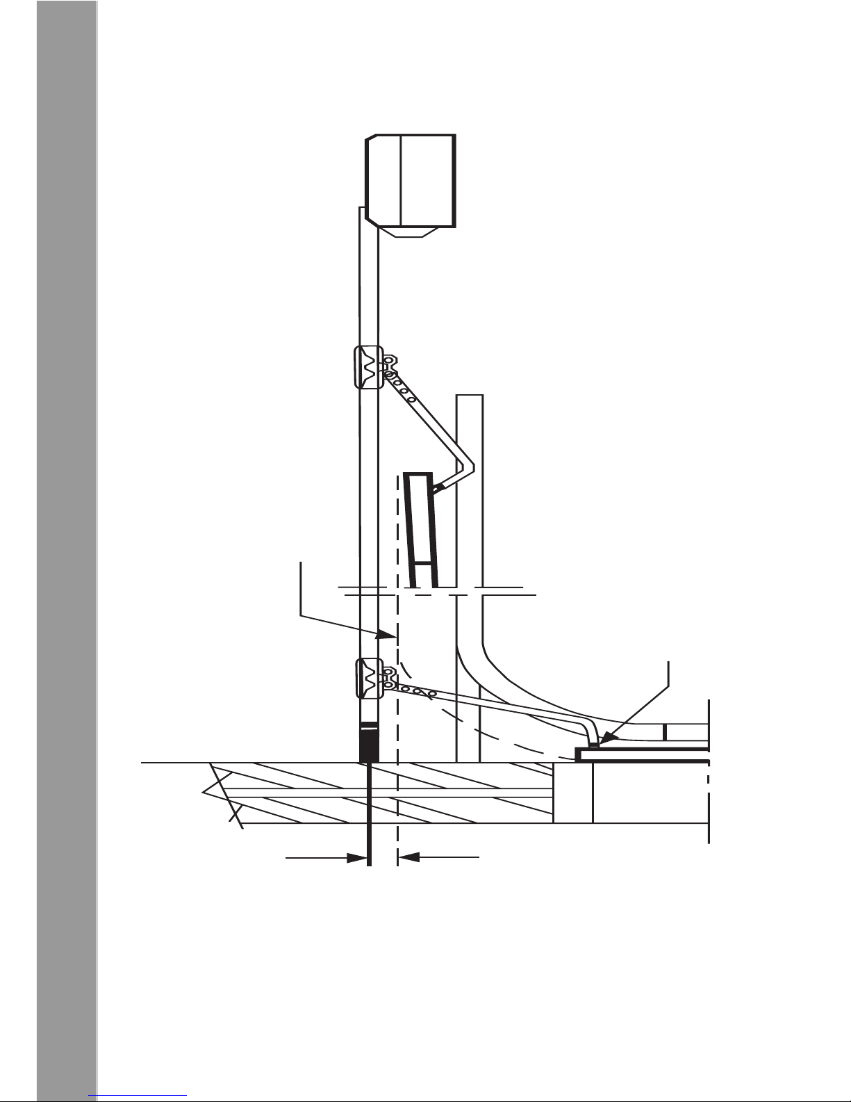
OVERHEAD SECTIONAL TYPE DOORS
INSTALLING THE HARDWARE
Figure 12.1
HIGHEST POINT
OF DOOR TRAVEL
DOOR BRACKET
LEVEL WITH ROLLER
IN TOP BRACKET
50mm
13
INSTALLING THE HARDWARE
OVERHEAD SECTIONAL TYPE DOOR
(refer to diagram on page 12)
Locate and mark off the
centre position on the inside
fascia on the spine (top edge)
of the top panel of the door, in
line with roller in top bracket.
Figure 13.1
While holding the door mount bracket in place on the centre position
mark the mounting hole positions.
Using your 5mm wood drill bit, drill pilot holes into the door spine where
you have just marked the door.
Fasten the door mount bracket to the door, using your 13mm spanner
or wrench and 2 of the M8 x 40mm coach screws.
Fasten the link arm to the door
mount bracket, using your
13mm spanners and/or
wrenches and 1 of the M8 x
25mm hexagonal bolts and M8
Nylock nuts.
Figure 13.2
Be certain not to over tighten the nut and bolt as the link arm must be
able to swing freely up and down in the door-mount bracket.
When you have completed the above, move on to Step 3 - Determining
the mounting position and mounting of the drawbar front-end.
A=B
A
B

14
INSTALLING THE HARDWARE
STEP 3 - DETERMINING THE MOUNTING POSITION, AND MOUNTING OF THE
DRAWBAR FRONT-END
TIP UP TYPE DOOR (Refer to diagram on page 10)
OVERHEAD SECTIONAL TYPE DOOR (Refer to diagram on page 12)
With the door in the closed position swing the link arm up fully vertical,
in line with the centre mark previously determined in Step 2.
For a TIP UP TYPE DOOR:
Measure strictly 275mm (two
hundred and seventy-five millime-
ters) above the top edge of the
door along the link arm.
Mark the wall at this point.
Figure 14.1
For an OVERHEAD SECTIONAL TYPE DOOR:
Measure strictly 50mm (fifty
millimeters) above the highest
point of travel of the door
along the link arm (use
horizontal tracks for door height
reference).
Mark the wall at this point.
Figure 14.2
FOR BOTH TYPES OF INSTALLATION:
You now use your 13mm masonary drill bit to drill a hole approximately
90mm deep at position marked on wall.
Fasten the wall mount bracket to the wall using the M8 Rawl bolt by
means of your 13mm spanner/ wrench.
When you have completed the above for your type of door, move on
to Step 4 – Determining The mounting position of the motorhead.
275mm on the wall
HIGHEST POINT
OF DOOR TRAVEL
HORIZONTAL TRACK
50mm
15
STEP 4 - DETERMINING MOUNTING POSITION OF MOTORHEAD UNIT
TIP UP TYPE DOOR (Refer to diagram on page 10)
OVERHEAD SECTIONAL TYPE DOOR (Refer to diagram on page 12)
With the door in the closed position, fasten front-end moulding into wall
bracket using the M8 x 90mm hexagonal bolt and a M8 Nylock nut.
Fasten using your 13mm spanners and/ or wrenches.
Lift motor unit out of the way of the door travel, supporting it with a
stepladder 90O to wall.
Release the sledge from the bobbin by pulling the release lever down
90O to drawbar. This will assist in the attaching of the linkarm to the
sledge mounting.
Fasten the link arm to the sledge, using your 13mm spanners and/or
wrenches and 1 of the M8 x 25mm hexagonal bolts and M8 Nylock nuts.
Be certain not to over tighten the nut and bolt as the link arm must be
able to swing freely up and down in the sledge mounting.
For OVERHEAD SECTIONAL TYPE DOOR installation, open door and
support motorhead so that the drawbar is 50mm above the door (level
with your spirit-level).
For TIP UP TYPE DOOR:
Open door to check travel clearance.
Ensure link arm is in the horizontal position when door is horizontal.
INSTALLING THE HARDWARE
HIGHEST POINT
OF TRAVEL
180o
Now proceed to Step 5 - Mounting the motorhead unit and
hanging straps.
Figure 15.1
DOOR AND LINK ARM SHOULD BE LEVEL

16
Figure 16.1
Mount the hanging straps to the fixed structure or rafters with 2 of the
M8 x 40mm coachscrews provided.
DO NOT exceed one hanging angle length from fixed structure or
rafters. In the case of double volume roof clearance, manufacture
or extend stable support structure down.
Mount powerhead to hanging straps with 2 of the M8 x 16mm
hexagonal bolts and Nylock nuts provided, using your 13mm
spanners and/ or wrenches.
Use the last 2 of the M8 x 16mm hexagonal bolts and Nylock nuts
with your 13mm spanners and/ or wrenches, to mount cross-
bracing.
Ensure that sufficient cross-bracing is used to disable any sideways
sway of the motorhead when in operation.
You can now commence with the programming and commissioning
schedule.
INSTALLING THE HARDWARE
PERPENDICULAR
RAFTERS
SOLID ROOF
PARALLEL RAFTERS
STEP 5 - MOUNTING MOTORHEAD UNIT AND HANGING STRAPS
Measure, cut and prepare the hanging straps according to the type of
fixed structure or rafter to which the unit is to be mounted.

17
WIRING & SCHEMATICS
EXTERNAL RECEIVER
Figure 17.1
BEAMS
Figure 17.2
To (+) of receiver
(+)
(C)
To (-) and/ or com of receiver
200mA max.
(BT)
From N/O or neg. out of receiver
To (+) of beams
(+)
(C)
To (-) and/ or com of beams
200mA max.
(Bm)
From N/O of beams

18
WIRING & SCHEMATICS
WALL CONSOLE
Figure 18.1
PROGRAMMING
Figure 18.2
(+) RED
(C) BLACK/ BLUE
(L) GREEN
(BT) WHITE
RECEIVER (B) (L)
PROGRAMMING
PRG L.E.D.
PRG JUMPER
PCB BUTTON

19
WIRING & SCHEMATICS
AUTO-CLOSE
Figure 19.1
LOAD POT
Figure 19.2
LOAD POT
AUTO-CLOSE JUMPER
PRG JUMPER

20
PROGRAMMING & COMMISSIONING
Programming a remote transmitter into the onboard receiver (Fig 18.2)
The receiver can learn one code for the garage door control button and
one code for the light control button.
1. Code the transmitter with a unique code as per make and model of
transmitter (refer to supplier for more information).
For the garage door control button:
1. Short the pin B to the middle pin with the jumper supplied
2. Press the desired button on the transmitter
3. The PRG LED will flash to indicate that the code has been memo-
rized.
4. Remove the jumper.
For the light control button:
1. Short the L pin to the middle pin with the jumper supplied
2. Press the desired button on the transmitter
3. The PRG LED will flash to indicate that the code has been memo-
rized.
4. Remove the jumper.
Erasing the codes on the receiver
The onboard receiver uses overwrite procedure.Recode the transmitter to a
new code and follow the process above.
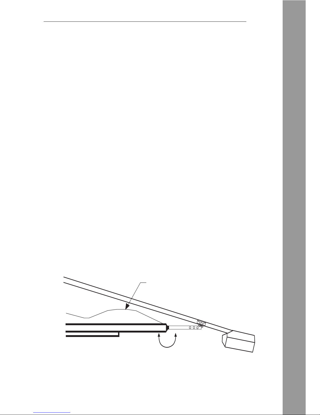
Setting up the open and closed positions
The Challenger MKIII relies on magnetic limits switches for the open and
close positions and uses intelligent profiling of the door’s operation for the
overload (sensitivity) function
1. Clear away any obstacles
2. Move the door so that the
bobbin on the chain slides into the
carriage or sledge.
Make sure the sledge pull clip is
in the engaged position.
Figure 20.1
To begin programming the unit:
Power up by plugging the three-pin plug attached to the Challenger into a 15Amp
plug socket (check with electrician for latest SABS compliancy).
NOTE: The unit should beep 5 times if it has never been programmed before
and once if being reprogrammed.
Table of contents
Other E.T. Systems Garage Door Opener manuals


Popular Garage Door Opener manuals by other brands


Automatic Technology Australia
Automatic Technology Australia GDO-5-AS installation instructions

CAME
CAME FAST-S24 KIT installation manual

Genie
Genie CHAINMAX 1200 4022 Operation and maintenance manual

SOMFY
SOMFY KEASY L+ manual

Chamberlain
Chamberlain 84505R owner's manual

Ricon
Ricon RDO2700 Series Service manual

Chamberlain
Chamberlain 1280R 1/2 HP owner's manual

Chamberlain
Chamberlain RJO20C manual

moore o matic
moore o matic X125 Installation and operation manual

SAMT
SAMT RGD350 Installation instructions and user guide

Nortek
Nortek GoControl GD00Z-4 Installation instructions manual

BPA
BPA BPA500 Assembly and operating instructions