E.T. Systems DC BLUE ADVANCED User manual


ET DC BLUE ADVANCED INSTALLER 2012.025.12.05.2014
2
www.et.co.za
TABLE OF CONTENTS
Page
Category
Introduction
3
Safety obligations and general warnings.
4
Technical specifications.
5
Component identification and descriptions.
Hardware installation
6
Installing the clutch release mechanism on the sledge/traveller.
7
Sectional overhead door – Installing the wall mount bracket.
7
Sectional overhead door – Installing the drawbar and hanging straps.
8
Sectional overhead door – Installing the door mount bracket.
8
Sectional overhead door – Installing the link arm.
8
Sectional overhead door – Testing the mechanical drive and linkage.
9
Trackless tip-up door – Installing the wall mount bracket.
10
Trackless tip-up door – Installing the door mount bracket.
10
Trackless tip-up door – Installing the link arm and hanging straps.
10
Trackless tip-up door – Testing the mechanical drive and linkage.
11
Both doortypes – Attaching the motor-head to the drawbar.
11
Both doortypes – Attaching the battery to the drawbar.
11
Both doortypes – Supplying household mainspower to themotor-head.
Control card wiring and setup
12
Wiring of optional extra devices to the system.
13
Control panel dashboard and programming menu summary. (How to navigatethe menu)
14
Programming - Open and closed limit setupand door loadprofiling.
15
Programming - Setting the obstructionforce sensing, safety level.
16
Programming - Activating safety beam mode.
17
Programming - Activating and selecting the auto-close time.
18
Programming - Selecting an electric lock mode.
Receiver programming
19
Learning anew transmitterbuttoncode into the receiver memory.
20
Clearing a single transmitterbuttoncode from the receiver memory.
21
Master erasing all transmitter buttoncodes from the receiver memory.
22
Quick method oflearning a transmitter buttoncode into thememory without entering the
programmingmenu.
Operating
23
Basic operating features using the (BT) buttontriggers.
25
Advanced operating features - Party mode.
26
Advanced operating features - Holidaylock-out mode.
27
Advanced operating features - Strike lock mode.
28
Advanced operating features - Magnetic lock mode.
29
Advanced operating features - Auto-close example.
29
Advanced features - Safety beam example.
30
Advanced features - Courtesy light operation.
Troubleshooting
31
Buzzer, courtesy light and displaywarnings.
Warranty
32
Warranty terms and conditions.

ET DC BLUE ADVANCED INSTALLER 2012.025.12.05.2014
3
www.et.co.za
IMPORTANT WARNINGS TO THE INSTALLER AND GENERAL SAFETY OBLIGATIONS
•Caution! Itisimportantforpersonal safetytofollowalltheinstructionscarefully.Incorrectinstallationormisuse
may cause serious personal harm.
•Keepthe instructionsina safe place forfuturereference.
•This product was designed and manufactured strictlyfor the use indicatedin this documentation.Any other use
not expresslyindicatedinthis documentation,may damage the product and/or be a source of danger.
•Weaccept no responsibilitydue toimproperuse or incorrect installationofthis product.
•Wewillnot accept responsibilityiftheprinciplesofgoodworkmanshipare disregardedby the installer. The
constructionofthedoor mustbe soundand automatable.Itistheresponsibilityoftheinstallertoensurethat all
mountings to the door are sufficient to withstand the necessaryforces in cases of overload.
•It is highly recommended that a set ofsafety infra-redbeams be used in conjunctionwiththis product.
•Overand abovetherecommendation touse safetyinfra-redbeams withthisproductitismandatory toinstall
and use a safetybeam set whenusing the automaticclosingfeature.
•Weaccept no responsibilityregardingsafetyand correct operationoftheautomationifothermanufacturer’s
equipment is added to this product.
•Do not make any modificationsoralterationstothisproduct.
•Anything other than expresslyprovidedfor in these instructions is not permitted.
•Priorto installation:
oThe door must be balanced correctlyto the tensioningsystem.Whenoperatedby hand the door
should be free of hindrance and easilymoved. Whenleft at any positioninits travel,thedoor should
neitherrisenor fall.If thedoor does riseor fall,re-balance the tensioningsystem.(Tensioning should only
be carriedout by a qualifiedand experiencedperson)
oThe doormaterialmust be sound and whole. Ensure theareas where the operatorattacheshavebeen
re-enforced.The door hardware must be in good serviceablecondition.
oEnsure the wall abovethe door issound and strongenough toallowproper fixingof theoperator. If
necessaryuse throughboltsand/or crossbrace platetospreadtheload. (Typicallyoncinder brickor
hollowwalls)
oThe DC BlueAdvancedisdesignedforweatherproofapplicationsonly.Installincompletelywalledand
roofedgarages only.
oEnsure the area of installationis not subject to explosivehazards. There should be no volatilegassesor
fumes as thesecan present aserioussafetyhazard.
oThe DC BlueAdvancedisdesignedtobe usedinlowtrafficapplicationsonly.Do not installondoors
usedfor multiparkinggarages likeofficeparksor apartment blockswithasingleentrance.
oThe DC BlueAdvanced issuppliedwithasealed15Asafetyplug on leadfor use in an electrical code
of practiceapprovedplugpoint.Do not extend,modify orreplacethe plug lead unless dulyqualified
as an electrician.Before installingthe unit,ensure the mains supply is switchedoff.
oItisthe responsibilityoftheinstallertoascertainthat thedesignatedpersons(includingchildren)
intendedto use thesystem, do not sufferreducedphysical sensoryormental capabilities,orlack of
experienceand knowledge, unlesstheyhave beengivensupervisionor instructionconcerningthe use
of thesystem by a person responsible fortheir safety.
oThe drivemaynotbe installedona doorincorporatingawicketdoor,unlessthe driveisdisabledbythe
releaseof thewicket door. (Wicketdoor:- A pedestriandoor withinthemain door)
Cont.…..

ET DC BLUE ADVANCED INSTALLER 2012.025.12.05.2014
4
www.et.co.za
•Installation:
oRemoveall cables, latches/locks orcatchesnot necessaryfor automation.
oEnsure the working areaisclearof obstructionsandobstacles.
oInstall thedoorstickerdepictingthesafetyreversetest andkeeping door area clear.This stickershould
be fixed to theinside surface of the door or near any permanent door control switches suchas a wall
consoleifinstalled.
oThe emergencyreleasecordmust be installedwhereit isno higher than 1.8mfrom thefloorlevel.
oAny additionalfixeddoor control switchessuchas wallconsoles,ifinstalled,must be at a heightof at
least 1,5m, withinclear sight of the door and away from any movingcomponents of the system.
oDo not substitute any component of DC BlueAdvanced withany other manufacturer’s part. ET
Systemsacceptsnoresponsibilityforthesafetyand correctoperationofthe automationsystemifany
of thesepointsare ignored.
•After Installation: It isthe responsibility of the installer to ensure the user:
oIs proficient intheuse of themanual emergency releasemechanism.
oIs issuedwiththe documentationaccompanying this product.
oUnderstandsthat the door may not be operatedout of clearsight.
oEnsures that childrenare kept clear of thedoor area and that childrendo not play withthe remote
transmitters.
oIsinstructednottoattempttorepairoradjusttheautomationsystemand tobeawareofthe danger
of continuingtouse the automationsystemin an unsafe conditionbefore a service providerattends to
it.
oIs proficient intestingthe unit’s safetyobstructionsensing systemby means of placinga 40mm high
object (woodenblock) below the door in the closedposition.On contact withtheobjecttheunit must
reversethedooraway and back to theopen position.
* Based on the assumption that the door is balanced correctly and moving freely.
TECHNICAL SPECIFICATIONS
Primary power supply
220 – 240Vac @ 50hz
Power consumption
120W peak @ (220 -240vac)
Motor voltage
24V dc
Maximum operations per day
50 full cycles per 24hrs @ a rate of Max. 2 per hour
Traveller speed*
8m/min
Operating temperature range
-10 to 50° C (14F to 122F)
Anti-crushing safety sensing
Yes - Electronic digital profiling
Auxiliary supply output
24Vdc @ 250mA peak or 150mA continuous
Rated battery charging voltage
27.5Vdc
Built in receiver format
ET BLU MIX © enhanced rolling code.
Receiver frequency
433.92Mhz
Memory
EEPROM
Applicable door types
One piece trackless tip-up or multiplepanel sectional
overhead doors
Drawbar options(Ex-stock)
2.2m or 3.2m or 3.7m
Applicable door sizes
<13m²

ET DC BLUE ADVANCED INSTALLER 2012.025.12.05.2014
5
www.et.co.za
COMPONENT IDENTIFICATION AND DESCRIPTIONS
Diagram
number Description Qty
Diagram
number Description Qty
1
Wall mount bracket
1
20
Nylock nuts M8
8
2
Pivot pin8mm x 90mm
1
21
Flat washers M6
6
3
Cotterpins1.8mm x 35mm
3
22
Coach screws8 x 60mm
2
4
Door mount bracket
1
23
Coach screws8 x 40mm
6
5
Straightlinkarm
1
24
Wallplugs10mm
2
6
Curved linkarm extension
1
25
Warning sticker
1
7
Emergency releaseassembly
1
26
24Vdc3.5A/hBattery(Optional extra)
1
8
Round head machine screws M6 x
20mm 4
27 Motor-head 1
9
Emergency releasecord1.1m with
warning tag
1
28 Control panel dashboard 1
10
Emergency releasecordplastic
knob/handle
1
29 Courtesylight diffuserlens 1
11
Pivot pins8mm x 25mm
2
30
Drawbar
1
12
Hanging strapdrawbar attachment
bracket
1
31
Drawbar spring dampener and shock
absorber
1
13 Drawbar brackets 3
32
Batteryconnectionbeneathdust
coversticker
1
14 Batterystraps 2
33
E-Coms connectionplug with dust
cover 1
15
Hanging straps 1m
3
34
Drawbar back-end
1
16
Machine bolts10mm head M6 x 15mm
2
35
Splinedsprocket withchain
1
17
Machine bolts14mm head M8 x 15mm
8
36
Household mains cord 1.5m
1
18 Machine nuts M6 4
37
Auxiliariesconnectionplugwithdust
cover 1
19
Nylock nuts M6
6
38
Coverscrews
4

ET DC BLUE ADVANCED INSTALLER 2012.025.12.05.2014
6
www.et.co.za
HARDWARE INSTALLATION
INSTALLING THE MANUAL OVERRIDE CLUTCH ASSEMBLY ONTO THE SLEDGE/TRAVELLER
(See page 5 for component identification)
The diagrams below show how to install themanual override clutch assembly onto the
sledge traveller. Ensure the 4 machine screws are securely fastened. Do this prior to
installing thedrawbar.
! CAUTION
TO DISENGAGE AND
MOVE DOOR
MANUALLY:
Warning! Door may plummet
closed when released.
W hile pulling the emergency
release cord downw ard, move
t he door open or closed by
hand.
TO RE-ENGAGEAND
LOCK DOOR BACK
ONTODRIVE:
Let the cord go and move
door open or closed unt il the
sledge/t raveller locks back
onto the chain drive.
Install the manual override label as shown here.
ET DC BLUE ADVANCED INSTALLER 2012.025.12.05.2014
7
www.et.co.za
HARDWARE INSTALLATION
Standard Single Track or Double Track Sectional Garage Door Method
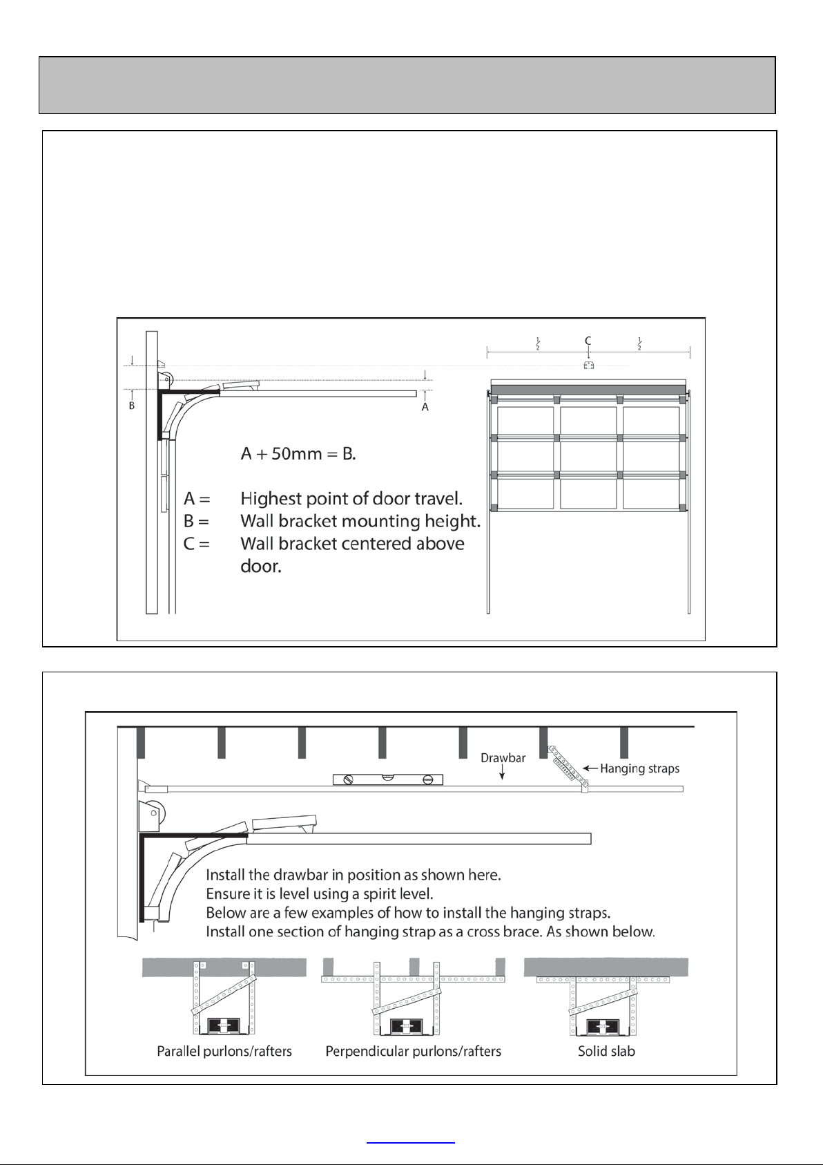
INSTALLING THE WALL MOUNT BRACKET (See page 5 for component identification)
The diagram below shows how to determine the mounting height and position of the wall mount bracket,
in the case of a standard single track or double track overhead sectional garage door system.
NB!!! The wall mount bracket is one of the components that take the majority of the load in a garage door
automation system. Extra care needs to be taken to ensure the bracket is securely fastened and that
whatever the bracket is fastened to, can withstand force equal to the force of the door when the spring
balancing of the door is removed (snapped)
INSTALLING THE DRAWBAR AND HANGING STRAPS (See page 5 for component identification)
ET DC BLUE ADVANCED INSTALLER 2012.025.12.05.2014
8
www.et.co.za
TESTING THE MECHANICAL DRIVE AND LINKAGE
It is now possibleto test the mechanical movement of the door with thelink arm attached and the
sledge/traveller engaged onto the chain drive. The movement of the door throughout its travel should be
approximately the same whilepulling the chain around the drawbar, as it is when the chain is not
engaged.
If satisfied that the drawbaris not causing unnecessary drag or hindrance to the door movement, then go
ahead and attach the motor-head to the drawbar. (Page 11)
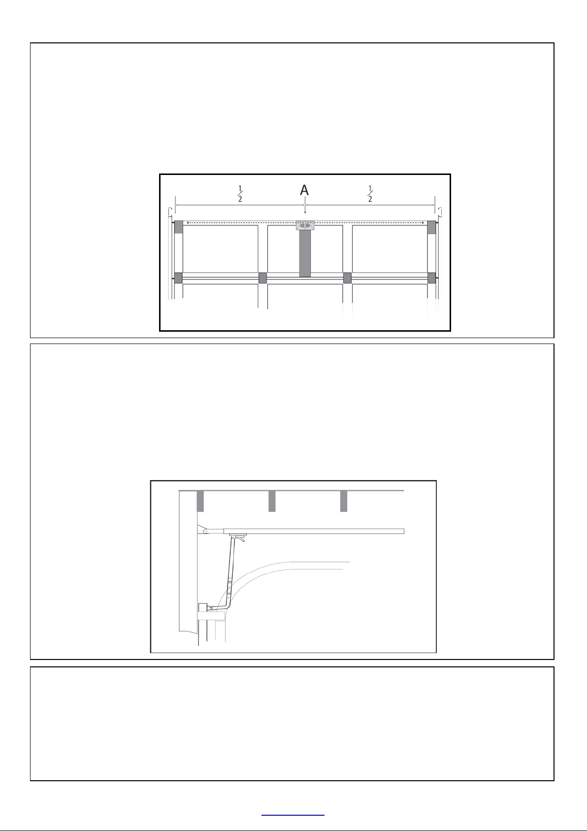
INSTALLING THE DOOR MOUNT BRACKET (See page 5 for component identification)
Mount the door mount bracket on the inside fascia of the dooras shown below. Keep it as in line as
possible with thetop guide rollers and centred from side to side of the door.
NB!!! The door mount bracket is one of the components that will take the majority of the load in a garage
door automation system. Extra care needs to be taken to ensure that the bracket is securely fastened.
Whatever the bracket is fastened to, must also withstand a force equal to the force of the door when the
spring balancing of thedoor is removed. For example if a balancing spring snaps.
INSTALLING THE LINK ARM (See page 5 for component identification)
Close the door fully. Install the curved link arm extension in the door mount bracket using one of the cotter
pins and 25mm long pivot pinssupplied.Next using the other 25mm longpivot pin and cotter pin, install
the straight link arm in the traveller/sledge that has been moved all the way to the front of the drawbar.
Finally bolt thecurved extension to the straight link arm, so that the two combined form the same angle as
shown below.
This method providesbetter positivelockingofthe doorin the closed positionthanthe commonlyused 45⁰
angled link arm. This method also produces less backward force on the gearbox when trying to compress
the seal at the bottom of thedoor as the downward force is generated by the link arm camming up and
over the door.

ET DC BLUE ADVANCED INSTALLER 2012.025.12.05.2014
9
www.et.co.za
HARDWARE INSTALLATION
Trackless tip-up door
INSTALLING THE WALL MOUNT BRACKET (See page 5 for component identification)
From the top edge of the door in the closed position, measure 275 – 300mm perpendicular to the top
edge of the door. Install the wall mount bracket at this height where it is positioned above the centre of
the door as shown in the diagram below.
NB!!! Thewall mount bracket is one of the components that will take the majority of the load in a garage
door automation system. Extra care needs to be taken to ensure that the bracket is securely fastened.
Whatever the bracket is fastened to, must also withstand a force equal to the force of the door when the
spring balancing of thedoor is removed. For example if a balancing spring snaps.
ET DC BLUE ADVANCED INSTALLER 2012.025.12.05.2014
10
www.et.co.za
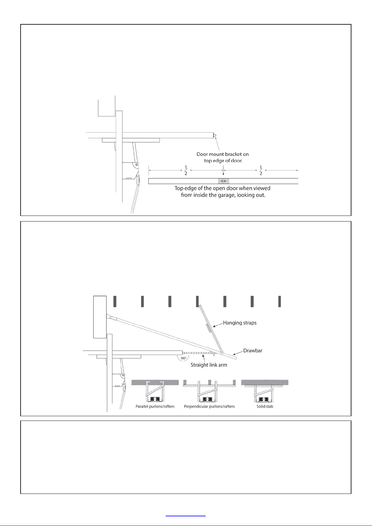
INSTALLING THE DOOR MOUNT BRACKET (See page 5 for component identification)
Mount the door mount bracket on the top edge of the door, where it is centred from side to side of the
door.
NB!!! The door mount bracket is one of the components that will take the majority of the load in a garage
door automation system. Extra care needs to be taken to ensure that the bracket is securely fastened.
Whatever the bracket is fastened to, must also withstand a force equal to the force of the door when the
spring balancing of thedoor is removed. For example if a balancing spring snaps.
INSTALLING THE LINK ARM AND HANGING STRAPS (See page 5 for component identification)
Install the front end of the drawbar in the wall mount bracket using the 90mm pivot pin and one of the
cotter pins. Raise the drawbar up and out of the way of the door. Install the link arm into both the
sledge/traveller and door mount bracket using the 25mm pivot pins and remaining two cotter pins.
Prepare and install the hanging straps so that when the door is in the full open position, thelink arm lays
180⁰to the door. Do not use the curved link arm extension in thistype of installation. The diagram below
shows the final position of the drawbar when installedand examples of how to prepare the hanging
straps.
TESTING THE MECHANICAL DRIVE AND LINKAGE
It is now possibleto test the mechanical movement of the door with thelink arm attached and the
sledge/traveller engaged onto the chain drive. The movement of the door throughout its travel should be
approximatelythe same whilepullingthe chain around the drawbar, as it is when the chain is not
engaged.
If satisfied that the drawbar is not causing unnecessary drag or hindrance to the door movement, then go
ahead and attach the motor-head to the drawbar. (Page 11)
ET DC BLUE ADVANCED INSTALLER 2012.025.12.05.2014
11
www.et.co.za
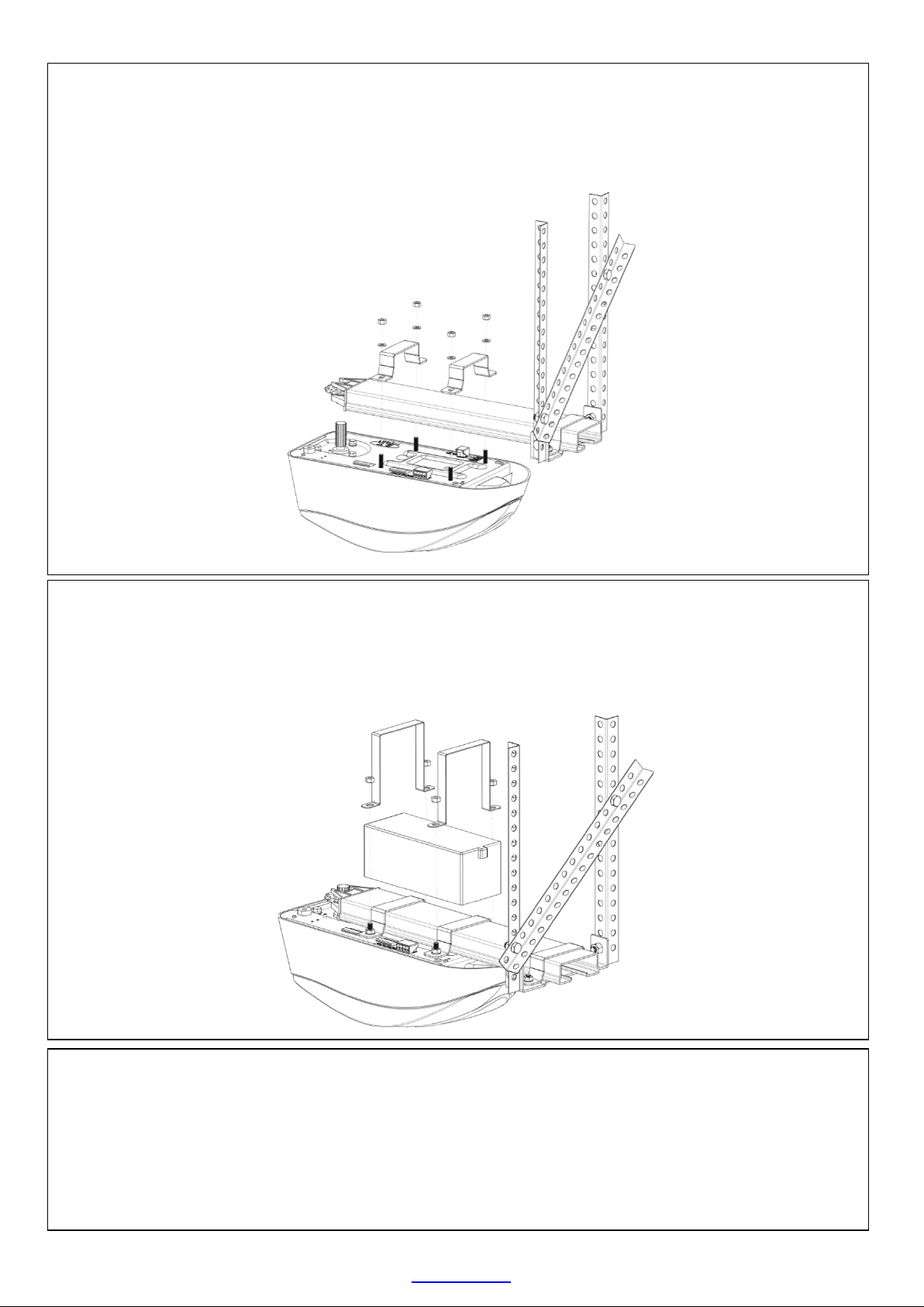
ATTACHING THE MOTOR-HEAD TO THE DRAWBAR (See page 5 for component identification)
Insert the splined motordriveshaft intothe splined sprocket at the back-end of the drawbar. Swivel the
motor-head around so that the motor mounting straps are able to fit over the drawbar and onto the
mounting studs on the motor-head. Fasten the drawbar mounting straps onto the motor-head using the 4
M6 machine nuts and M6 flat washers.
ATTACHING THE BATTERY TO THE DRAWBAR (See page 5 for component identification)
Making use of the extended length mounting straps and 4 of the M6 Nylock nuts fasten the batteryatop
the drawbar as shown below. Remove the sticker covering the battery plug socket on the motor-head
and insert the battery lead plug. The battery plug is moulded in such a way as to only be inserted in one
direction. Ensure the plug is in firmly.
SUPPLYING HOUSEHOLD POWER TO THE MOTOR-HEAD
The DC BLUE ADVANCED © comes supplied with an IEC and SANS compliant 220Vac power cord, 1,5m in
length. Plug the sealed non-serviceable 3 pin 15Amp plug into a certified 15Amp plug socket that is
installed outside of the workingsof the garage door system, yet still within reach of the power cord. Ensure
the there is no strain on the cord once installed. Also ensure that nothing will catch or snag the power
cord when the garage door is moving or when people or cars pass below the system.


ET DC BLUE ADVANCED INSTALLER 2012.025.12.05.2014
13
www.et.co.za
CONTROL PANEL DASHBOARD AND PROGRAMMING MENU SUMMARY
(How to navigate the menu options)
NOTE! Before attempting to execute the instructions, read the
complete instruction table, for a setup option. Some steps require a
response before a safety timeout expires and you may still be
reading the next step when the timeout expires.
•To enter the Programming menu from Standby mode, press and
hold the “SET” button until the buzzer beeps twice.
•Once in the Programming menu, use the up and down buttons to
scroll between options.
•For further instruction on changing settings, refer to the instruction
tables on the page indicated for each option.
EXIT BUTTON
•To exit a setup option
without changing the
current setting for that
option, press and
release the “EXIT”
button. The menu will
exit back one level.
•Note 1: If the “EXIT”
buttonispressed
before completing
the Limit and door
profile setup, no limit
and door profile
settings will bein
memory. You must
complete this setup
to operate the door.
(See “P” symbol
displayed inthe
Trouble shooting
table on page 31)

ET DC BLUE ADVANCED INSTALLER 2012.025.12.05.2014
14
www.et.co.za
PROGRAMMING
Open and closed limit position setup and door load profiling.
From StandbyMode
Action
Response
To enter the program
menu. Press and hold SET
button until buzzer beeps
twice.
Displaybeginsflashing “P”
and buzzer beeps twice
to confirm the main
program menu is active.
Scroll up with the UP
button until “L” flashes.
Display flashes “L” to
confirm limit setup mode
is selected.
Press and release SET
button to begin limit
setup.
Buzzer beeps once and
“O” displays to indicate
open limit position must
be set.
Press and hold the UP
button to raise the door to
the required open
position.
The “n” symbol displays as
the door opens.
Fine tune using the UP
and DOWN buttons.
The “n” and “u” symbols
confirm thedoor direction
while fine tuning.
or
When satisfied the door is
in the correct open
position, press the SET
buttontoadvanceto the
close limit setup.
The buzzer beeps once
and the “C” symbol
displays to indicate the
closedlimit position must
be set.
Press and hold the DOWN
button to lower the door
to the required closed
position.
The “u” symbol displays as
the door closes.
Fine tune using the UP
and DOWN buttons.
The “n” and “u” symbols
confirm thedoor direction
while fine tuning.
or
When satisfied the door is
in the correct closed
position, press the SET
buttontoadvanceto the
automatic door load
profiling stage.
Door opens and closes
again.
The display confirms the
direction and the buzzer
will beep intermittentlyas
the motor runs.
When complete, the
control returns tothemain
program menu.
Display= Flashing “P”and
buzzer beeps once.
Scroll up or down
to next program
option.
OR
Press and release EXIT to
return to Standby mode.
See Note 1 on page 13!!!

ET DC BLUE ADVANCED INSTALLER 2012.025.12.05.2014
15
www.et.co.za
SAFETY OBSTRUCTION SENSING IN ACTION:
In the case of the door being resisted physically or obstructed while opening.
•The motor will stop running,
•The buzzer will beep once and operator reverts to standby mode.
•On the next BT buttontrigger the motor will start closing thedoor.
In the case of the door being resisted physically or obstructed whileclosing.
•The motor will stop running,
•The buzzer will beep once as the motor immediatelybegins opening the door once again.
•On reaching the open position the operator reverts to standby mode.
•On the next BT buttontriggerthe motor will beginthe door closing.
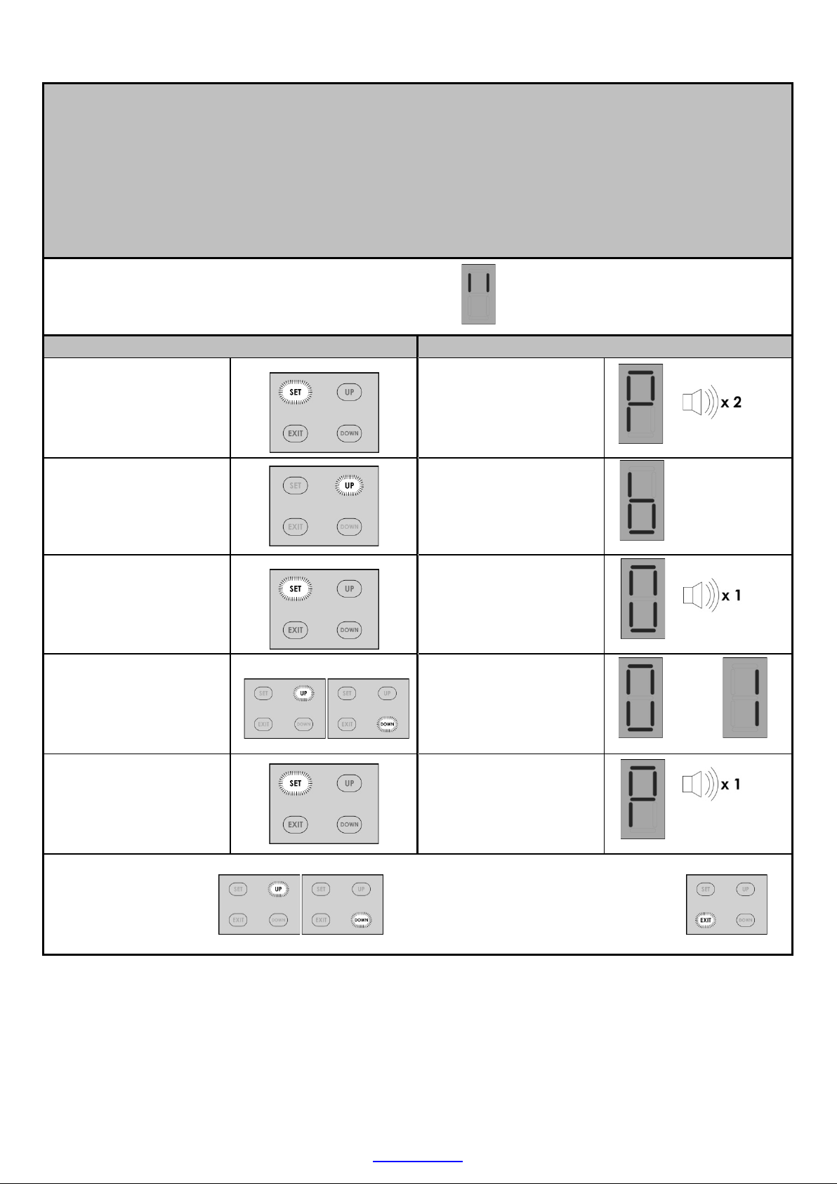
SETTING THE OBSTRUCTION FORCE SENSING, SAFETY LEVEL.
Default level - 3
From StandbyMode
Action
Response
To enter the Program
menu. Press and hold SET
button until buzzer beeps
twice.
Displaybeginsflashing “P”
and buzzer beeps twice
to confirm the main
program menu is active.
Scroll up with the UP
button until “F” flashes.
Display flashes “F” to
confirm safetyforce setup
mode is selected.
Press and release SET
button to enter safety
force setup.
Buzzer beeps once and
current safety force level
is displayed. (1-9)
Press and release the UP
or DOWN buttons to scroll
to the desired safety force
level. (1-9)
1 = most sensitive to
resistance in movement of
the door.
9 = least sensitive to
resistance in movement of
the door.
Press and release the SET
button to save the new
setting to memoryand
exit back to the main
program menu.
The buzzer beeps once
and the display returns to
flashing “P”.
To
Scroll up or down
to next program
option.
OR
Press and release EXIT to
return to Standby mode.
ET DC BLUE ADVANCED INSTALLER 2012.025.12.05.2014
16
www.et.co.za
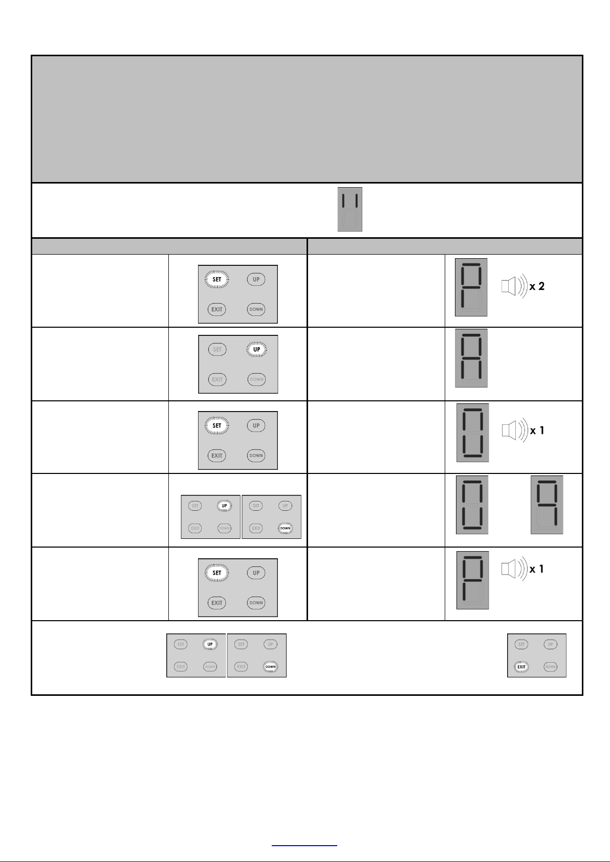
ACTIVATING SAFETY BEAM MODE.
Default – Off (Disabled)
NB! When auto-close mode is activated, the safety beam mode automatically becomes active.
This is mandatory as auto-close mode may never be used without a set of safety beams installed.
With auto-close active, safety beam setup mode is no longer available in the setup menu.
From Standby Mode
Action
Response
To enter the Program
menu. Press and hold SET
button until buzzer beeps
twice.
Display begins flashing
“P” and buzzer beeps
twice to confirm the
main program menu is
active.
Select safety beams
setup by scrolling upwith
the UP button until “b”
flashes.
Display flashes “b” to
confirm safety beam
setup mode is selected.
Press and release SET
button to enter safety
beam setup.
Buzzer beeps once and
current beam status is
displayed.
0 = Off and 1 = On
Press and release the UP
button for On or DOWN
button for Off selection.
0 = Off (Disabled)
1 = On (Active)
Press and release the SET
button to save the new
setting to memoryand
exit back to the main
program menu.
The buzzer beeps once
and the display returns to
flashing “P”.
OR
Scroll up or down
to next program
option.
OR
Press and release EXIT to
return to Standby mode.
ET DC BLUE ADVANCED INSTALLER 2012.025.12.05.2014
17
www.et.co.za
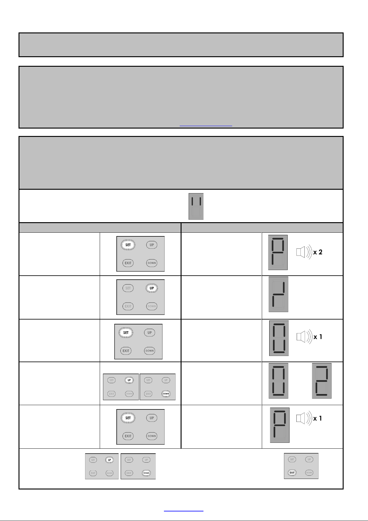
ACTIVATING THE AUTO-CLOSE MODE AND SELECTING AN AUTO-CLOSE TIME.
Default – Off
NB! When auto-close mode is activated, the safety beam mode automatically becomes active.
This is mandatory as auto-close mode may never be used without a set of safety beams installed.
With auto-close active, safety beam setup mode is no longer available in the setup menu.
From Standby Mode
Action
Response
To enter the Program
menu. Press and hold SET
button until buzzer beeps
twice.
Display begins flashing
“P” and buzzer beeps
twice to confirm the
main program menu is
active.
Select auto-close setup
by scrolling up with the
UP button until “A”
flashes.
Display flashes “A” to
confirm auto-close setup
mode is selected.
Press and release SET
button to enter auto-
close setup.
Buzzer beeps once and
current auto-close status
is displayed.
Press and release the UP
or DOWN buttons to scroll
to the desired setting.
0 = Off. 5 = 50 sec.
1 = 10sec. 6 = 60sec.
2 = 20sec. 7 = 70sec.
3 = 30sec. 8 = 80sec.
4 = 40sec. 9 = 90sec.
Press and release the SET
button to save the new
setting to memoryand
exit back to the main
program menu.
The buzzer beeps once
and the display returns to
flashing “P”.
To
Scroll up or down
to next program
option.
OR
Press and release EXIT to
return to Standby mode.
ET DC BLUE ADVANCED INSTALLER 2012.025.12.05.2014
18
www.et.co.za
SELECTING A LOCK MODE.
Default – Off
NB!! The “E-Coms” output on the control card is designated to be used with an “E-Coms” Relaymodule,
when using any electric lock. These modules are onlyavailable via ET Systems.
For further instructions on the E-Coms relaymodule, consult the instructions included with it.
For assistance the product support department can be contacted on:
0861 109 9238 or support@et.co.za
In strike lock mode, the lock relay will energise 0.5sec before the motor begins opening and release
again 0.5sec after the motor has begun moving. (Total 1sec. pulse length)
In magnetic lock mode, the lock relay will energise, 0.5sec before the motor starts opening and 5 seconds
later, the lock relaymodule switches off again. (Total 5sec. pulse length)
From Standby Mode
Action
Response
To enter the Program
menu. Press and hold
SET button until buzzer
beeps twice.
Display begins flashing
“P” and buzzer beeps
twice to confirm the
main program menu is
active.
Select lock setup by
scrolling up with the UP
button until “” flashes.
Display flashes “” to
confirm lock setup
mode is selected.
Press and release SET
button to enter lock
setup.
Buzzer beeps once and
current lock status is
displayed.
Press and release the UP
or DOWN buttons to
scroll to the desired
setting.
0 = Off.
1 = Strike lock.
2 = Magnetic lock.
Press and release the SET
button to save the new
setting to memoryand
exit back to the main
program menu.
The buzzer beeps once
and the display returns
to flashing “P”.
To
Scroll up or down
to next program
option.
OR
Press and release EXIT to
return to Standby mode.

ET DC BLUE ADVANCED INSTALLER 2012.025.12.05.2014
19
www.et.co.za
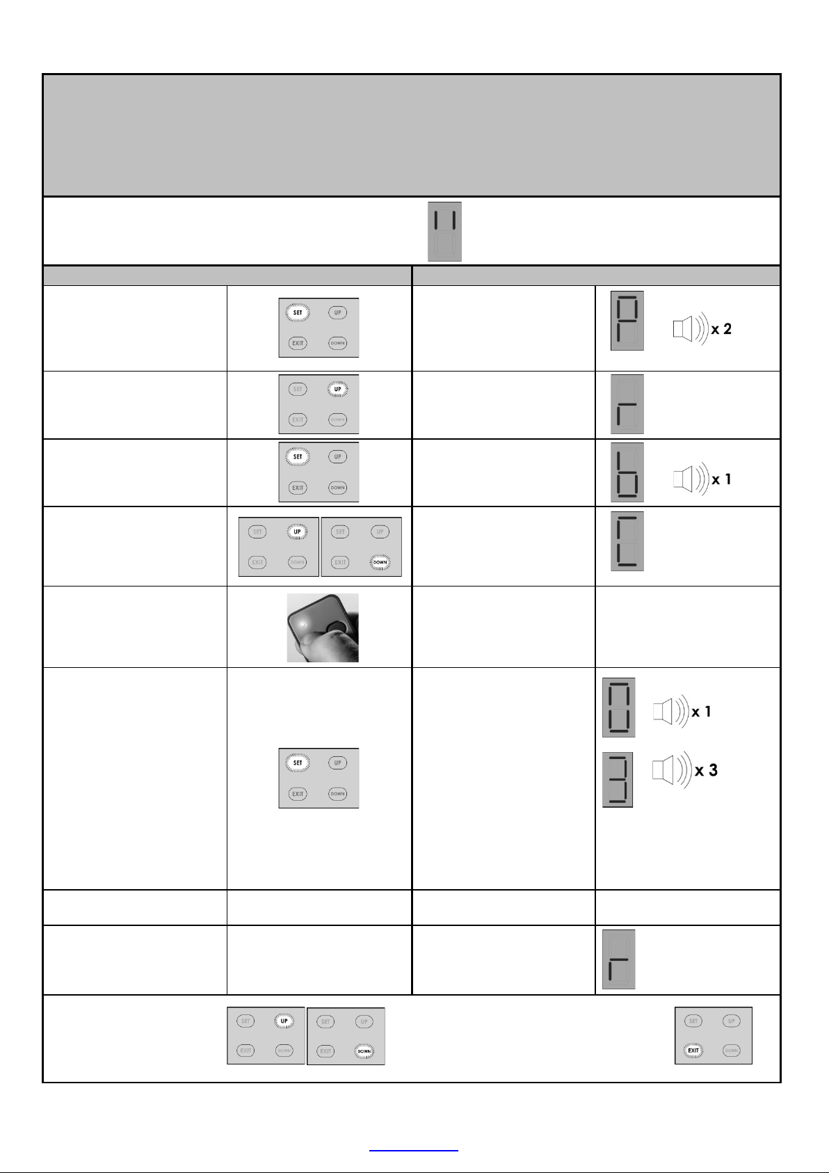
LEARNING A TRANSMITTER CODE IN THE RECEIVER MEMORY.
Max users (BT) button trigger channel = 35 user codes
Max users (LT) courtesy light trigger channel = 5 user codes
NB!! The built in receiver will only work with the ET BLU MIX © enhanced rolling code or ET BLUE rolling code
transmitters.
From StandbyMode
Action
Response
To enter the Program
menu. Press and hold SET
button until buzzer beeps
twice.
Displaybeginsflashing “P”
and buzzer beeps twice
to confirm the main
program menu is active.
Select receiver setup by
scrolling up with the UP
button until “r” flashes.
Display flashes “r” to
confirm receiver
programming menu is
selected.
Press and release SET
button to enter receiver
programming.
Buzzer beeps once and
“b” for (BT) is displayed.
Press and release the UP
or DOWN buttons to scroll
to thechannel theremote
button mustbe learnt into
.
b = (BT) button trigger
channel.
L = (LT) Courtesy light
trigger channel.
or
Press and hold desired
remote button.
LED onremotetransmitter
illuminates.
While still holding the
desired remote button,
press and release the
“SET” button.
“1”on displayand 1 beep
= user code successfully
learnt.
“2” on display and 2
beeps = user code
already in the receiver
memory.
“3” on display and 3
beeps = Unsuccessful
because no code was
seen within 4 sec of the
SET button being pressed.
Mandatorytimeout.
“F” on display and
multiple rapid beeps =
Memoryfull
The display returns to
flashing “r”. Receiver
programming menu.
Release the remote
button
Memory ful l
Code already in
memory
Successful
Unsuccessful
Scroll up or down
to next program
option.
OR
Press and release EXIT to
return to Standby mode.
ET DC BLUE ADVANCED INSTALLER 2012.025.12.05.2014
20
www.et.co.za
CLEARING A SINGLE TRANSMITTER BUTTON CODE FROM THE RECEIVER MEMORY.
This can only be completed if the remote control that must be erased is present.
If the remote control that must be removed is missing or unobtainable, then a master erase procedure
(Page 21) must be performed and the remaining, valid user codes must all be learnt into the memory once
again.
From Standby Mode
Action
Response
To enter the Program
menu. Press and hold SET
button until buzzer beeps
twice.
Display begins flashing
“P” and buzzer beeps
twice to confirm the
main program menu is
active.
Select receiver setup by
scrolling up with the UP
button until “r” flashes.
Display flashes “r” to
confirm receiver setup
mode is selected.
Press and release SET
button to enter receiver
setup.
Buzzer beeps once and
“b” is displayed.
Press and release the UP
or DOWN buttons to
scroll to the “C” option.
“C” is displayed.
Press and hold desired
remote button to be
erased.
LED on remote
transmitter illuminates.
While still holding the
desired button, press
and release SET button.
“0” on display and 1
beep = user code
successfully erased.
“3” on display and 3
beeps = Unsuccessful
because no code was
seen within 4 sec of the
SET button being
pressed.
Mandatory timeout.
Release the remote
button
Display reverts back to
flashing “r” to indicate
you have returned to the
receiver setup menu.
Unsuccessful
Scroll up or down
to next program
option.
OR
Press and release EXIT to
return to Standby mode.
Table of contents
Other E.T. Systems Garage Door Opener manuals


Popular Garage Door Opener manuals by other brands


CTM International
CTM International nfinity owner's manual

Craftsman
Craftsman 139.53915D owner's manual

LEXMAN
LEXMAN 3276007317091 instruction manual

Roger
Roger BG30 Series INSTRUCTIONS AND RECOMMENDATIONS FOR THE INSTALLER

B&D
B&D Easylifter installation instructions

Chamberlain
Chamberlain Series 651-2MM-1/2HP owner's manual

Henderson
Henderson g60 installation manual

Chamberlain
Chamberlain PD220 Assembly instructions

Chamberlain
Chamberlain Whisper Drive Security+ WD962KD owner's manual

Leb Electronics
Leb Electronics ARGO230 Instructions and warnings for installation, use and maintenance

Proteco
Proteco Q60S manual

Digidoor
Digidoor Paratrak installation instructions