E.T. Systems UMPETHA User manual

UMPETHA 082009/072010.014
1
Domestic sliding gate operator by ET SYSTEMS.
Installer instructions

UMPETHA 082009/072010.014
2
Table of contents
Page Category
Introduction
3 Safety obligations and general warnings
4 Identification of components
5 Technical specifications
6 Before installing preparation
7 Cable requirements
Hardware installation
8
9 Installing the baseplate and positioning motor
10 Inserting or remov ing battery and mounting of motor to baseplate
11 Installing the rack
13 Installing the limit actuator
14 Control card wiring layout
Motor control programming
15 Run time set-up
16 Auto-close time programming
17 Pedestrian opening and pedestrian auto-close time programming
18 Changing the crawl distance
19 Changing the switch type input for the beams
20 Adjusting the safety sensing lev el
Receiver programming
21 Master erase
22 Registering a transmitter using the receiv er pins
23 Registering a transmitter using the master remote transmitter
Operating mode selection
24 Standard mode
24 Simple auto-close mode
24 Complex auto-close/Condominium mode
25 P.I.R.A.C. mode
Additional features
26 Holiday lock-out
26 Beam Alarm Output (B.A.O)
27 Auto-close ov erride/party mode
27 Pedestrian operation
27 Courtesy light functionality
Trouble shooting
28 Buzzer indication trouble shooting guide
28 Status LED indication guide
29 Warranty
Accessing manual override and remov ing cov er

UMPETHA 082009/072010.014
3
WARNING TO THE INSTALLER. GENERAL SAFETY OBLIGATIONS.
Caution! It is important for personal safety to follow all the instructions carefully. Incorrect installation or misuse may cause serious
personal harm.
Keep the instructions in a safe place for future reference.
This product was designed and manufactured strictly for the use indicated in this documentation. Any other use not expressly
indicated in this documentation, may damage the product and/or be a source of danger.
We accept no responsibility due to improper use of this product.
Care must be taken not to install this product in an unsafe environment. I.e. near inflammable gases and or fumes.
We will not accept responsibility if the principles of good workmanship are disregarded by the installer. The construction of the
gate must be sound and automatable. It is the responsibility of the installer to ensure that all mountings to the gate are sufficient to
withstand the necessary forces in cases of overload.
Before carrying out any work on the product, ensure that the electrical supply is switched off.
It is highly recommended that a set of safety infra-red beams be used in conjunction with this product.
We accept no responsibility regarding safety and correct operation of the automation if other manufacturer’s equipment is added
to this product.
Do not make any modifications or alterations to this product.
It is the responsibility of the installer/ service provider to completely instruct and demonstrate the proper use of this product,
especially the emergency override, to the end user. It is also the responsibility of the installer/ service provider to issue all end user
documentation, which accompanies this product, to the end user.
Ensure that other persons, especially children are clear of the gate and opener before and during operation.
Keep remote transmitters away from children to prevent accidental activation of the system.
The end user should refrain from attempting to make any repairs or adjustments to the system and should contact professional
qualified assistance timorously.
Anything other than expressly provided for in these instructions is not permitted.
The electrical supply to this product must comply with the local electrical code of practice and any electrical work must be carried
out by a qualified electrician.
Over and above the recommendation to use safety infra-red beams with this product it is mandatory to ensure a set has been
installed and is in proper working condition when using the automatic closing feature.

UMPETHA 082009/072010.014
4
1. Plug in terminal connectors
13. Motor mounting slot
2. Control card
14. Manual override cam sensor magnet
3. Control card holder
15. Gearbox housing
4. Battery
16. Manual override cam reed switch sensor
5. Antenna
17. DC to DC switch-mode 12V Aux supply module
(300mA peak)
6. 220Vac 500mA fast blow fuse for primary supply*
18. Serial number
7. 220Vac 15A fixed terminal connections*
19. 24Vdc Fixed magnet motor
8. Inline unidirectional battery plug (polarized)
20. Revolution counter magnet
9. Cable entry point
21. Closed limit reed switch sensor
10. Manual override lock with protection flap
22. Base plate
11. Manual override cam
23. Pinion gear
12. Base plate
24. Pinion gear protection flange
*For built in transformer model.

UMPETHA 082009/072010.014
5
TECHNICAL SPECIFICATIONS
* Calculation based on a gate leaf ≤maximum length with a rolling resistance of ≤maximum rated gate resistance.
POWER SUPPLY @ GATE REQUIREMENT 29Vac 1Amp plug-in transformer model
220Vac for built in transformer model
MAXIMUM ABSORBED CURRENT @ 220V AC SUPPLY 100mA
MOTOR VOLTAGE 24Vdc
MAXIMUM STARTING RESISTANCE OF GATE < 10kgF set
MAXIMUM RUNNING RESISTANCE OF GATE < 6kgF set
GATE SPEED 16m/min @ maximum rated gate resistance
DUTY CYCLE 4 operations per hour*
OPERATING TEMPERATURE RANGE
ANTI-CRUSHING SAFETY SENSING ELECTRONIC
NETT. WEIGHT 10.70kg
MAXIMUM GATE LENGTH 6m
MAXIMUM GATE MASS 300kg
AUXILIARY OUTPUT FOR ANCILLIARIES 12Vdc at 300mA
-10 / +50°C
UMPETHA 082009/072010.014
6
BEFORE ATTEMPTING TO INSTALL A SLIDE GATE OPERATOR, PLEASE BE CERTAIN YOU HAVE READ AND
UNDERSTOOD THE FOLLOWING TO ENSURE CONTINUED SATISFACTORY SAFE SERVICE FROM THIS PRODUCT:
The following are points to note before installing your new slide gate operator:
1. Gate mechanics
2. Cabling requirements
GATE MECHANICS
a) Gate Leaf
Gate leaf must be sound and of sufficient construction to accommodate an operator of this type (see technical specifications).
Gate leaf should be straight and true with minimal deviation to the fascia that the rack must attach to (no ‘banana-effect’).
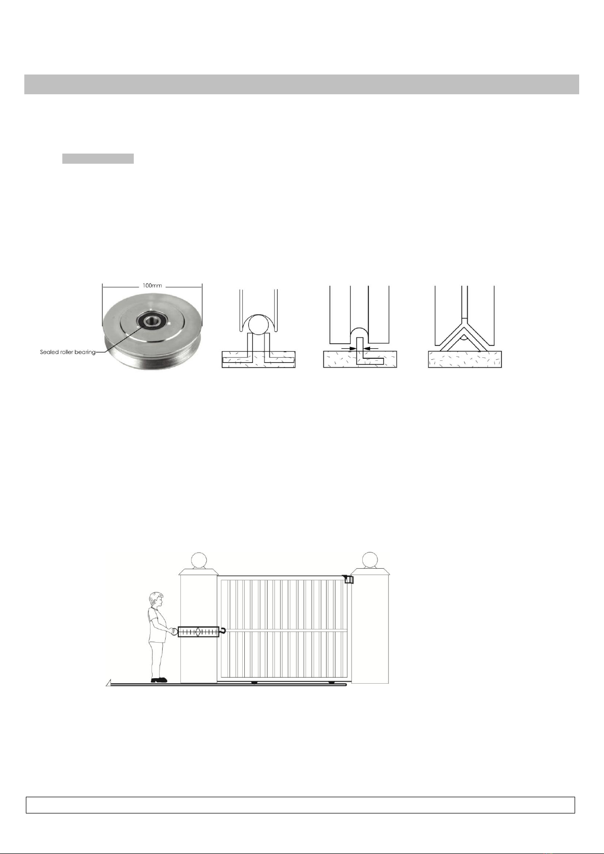
b) Wheels and track
The track must be secure, straight, level and free of all obstructions.
Recommended wheel type and size for this automation is steel or steel alloy, machined or cast wheels of at least 100mm diameter using
sealed roller bearings. The larger the wheel the less rolling resistance generated. Larger wheels also maintain their plumb and momentum
longer. When wheels are fixed in the gate, and not able to pivot, binding can occur if the gate is bowed (banana effect) For wheel profile
and matching track types, see the three examples below:
Recommended Less problematic Problematic
c) Guides
It is recommended that a roller guide consisting of a sealed roller bearing clad in nylon be used.
The guidance system should be installed at the top edge of the gate whenever possible. In cases where this is not possible the
guidance system should never be below the halfway point of the total gate height when the gate is in position on it's track.
In the case of a single guide roller running in a guide channel, ensure the guide never touches both inside walls of the channel
simultaneously. This causes the roller to snag as it tries to roll in both directions at once.
In the case of 2 guide rollers being used on either side of the gate leaf, ensure that both wheels never touch the leaf
simultaneously.
Avoid using more than 1 guide roller on the same side of the gate leaf to prevent binding.
As with the wheels the larger the guide the less rolling resistance generated.
d) Gate Travel
Using a fish-scale, as shown below, pull the gate fully open and fully closed at approximately the same speed as the operator you intend to
use (see technical specifications). For optimum duty cycle, ensure that the maximum resistance does not exceed 10kgF starting and 6kgF
running. The starting resistance should fall away within 300 to 500mm. Note the recommended track, wheel and guide types mentioned b)
and c) above.
NB! Install physical stoppers at the ends of the gate travel to avoid the gate over-running the ends of the track - as shown here. (National
safety standard requirement)

UMPETHA 082009/072010.014
7
CABLING REQUIREMENTS
Before mounting the operator ensure your cabling and conduiting are in place to prevent any inconvenience at a later stage. Allow for
spare cabling in case of faulty cable & breakages (especially important when using low specification cable). If installing an intercom,
remember to allow for sufficient cable cores for all the uses on the system as per manufacturers cabling requirements.
1
7
6
8
4
1
2
4
5
3
2. Safety infra-red beam power (2-core)
3. Safety infra-red beam power & switch (4-core)
4. Courtesy lights (twin + earth 1.0mm)
1. Intercom gate station (check with intercom
supplier specifications) 5. Free exit loop (1.5mm silicone insulated single
core flexible stranded)
6. Primary power: Plug in transformer model - twin:
min 0,5mm Internal in-line transformer model
(220Vac) - twin + earth: 1,0mm
7. From intercom internal equipment (check with
intercom supplier specifications)
8. Optional earth-rod for high lightning strike areas
(preferably use household earth leakage)

UMPETHA 082009/072010.014
8
Manually overriding the gearbox and removing the cover
Locked and engaged
Unlocked and engaged
Insert key and turn
clockwise.
Unlocked and
disengaged
Cover housing screw
beneath manual
override cam
Second cover screw
Fourth cover screw
Third cover screw
Remember to pull or push the gate gently until the gears “click” re-engage, before running the motor after a manual override.
When the override cam is in the manual override position the electronic control is disabled. To operate the control card the cam
must be in the engaged position.

UMPETHA 082009/072010.014
9
Motor positioning to gate.
Hot tip: Cast the track plinth at the same time as the motor plinth
Install the base plate on the protected side of the driveway wherever possible. (opposite side of the guide post to the driveway) The base
plate must be installed 30 to 50mm away from the proudest part of the gate. The wheel bolt is the proudest part of the gate here. If in doubt
rather install the base plate further away and use spacers between the gate fascia and the rack when installing the rack.
30 to 50mm between the proudest part of the
gate and the edge of the base plate
Guide post
Driveway
300mm
200mm
300mm
300mm
Base plate
Conduiting
Pre-cast concrete
plinth
Coach screws through
angle mounting tabs
10mm masonry drill bit.
Freshly cast concrete
plinth
Conduiting
Roofing bolts pre-
assembled onto base
plate
Base plate
Fold out tabs
Top view
Sectional side view of a baseplate set in a freshly cast plinth
Sectional side view of a baseplate mounted on a previously cast plinth

UMPETHA 082009/072010.014
10
Inserting and removing the battery
Fastening the operator to the base plate
Fasten motor to the base plate using the bolts and plates from the top as
shown here
Be careful that the cables are
not trapped and damaged
when fastening or adjusting the
motor on the base plate
Please note! In the cases where something like
the gate guide post or a wall is obstructing the
battery from being angled to one side, making
it impossible to insert or remove the battery
then carefully remove the control card and
control card holder before removing the
battery.
Remember to ensure the control card and
holder are both secured in place correctly
when finished.
UMPETHA 082009/072010.014
11
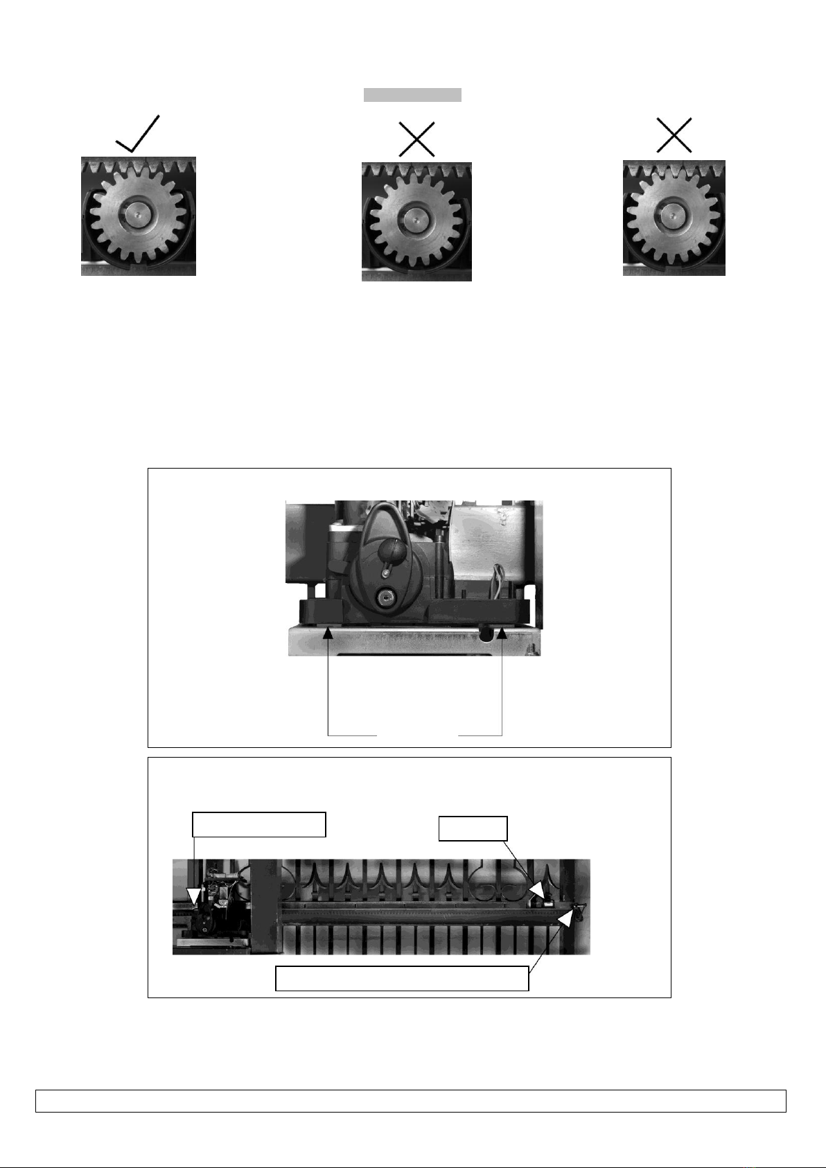
Installing the rack.
Rack to pinion spacing. Correct.
The driving surfaces of each tooth
are 1 to 2mm apart. Allowing for
slight variance in the height of the
rack when the wheels shrink in
colder conditions or where the
gate flexes and the rack is no
longer square to the pinion.
Rack to pinion spacing.
Space to large.
This will cause skipping at the
slightest resistance to the gate
travel, resulting in the motor
control going out of
synchronization to the gate
position. (Losing open limit) The
long term damage here will be
stripped teeth.
Rack to pinion spacing.
To tight.
This will cause unwanted rolling
resistance especially in colder
conditions. Where the wheel
shrinkage will cause the gate to sit
heavier on the pinion or the rack is
no longer square to the pinion due
to gate flex.(False safety sensing
activation)
Begin by fastening the motor atop the base plate with 2mm spacer plates between.
Spacer plates
Clamp the end of the first length of rack end to the closing edge of the gate. Rest the other end
of the length on the pinion as shown here. Use a spirit level to ensure the rack remains true.
Rack resting on pinion.
Spirit level
Rack end clamped to closing edge of gate

UMPETHA 082009/072010.014
12
If satisfied with the rack level fasten the first “TEK” screw (supplied) in the middle of the slot
nearest the closing edge of the gate.
Move the gate towards the open position. Far enough that you can access the last mounting slot
at the opposite end of the length of rack to the end already fastened. Fasten the next “TEK”
screw here while the rack still rests atop the pinion.
To install additional lengths of rack, move gate closed until the next length of rack meets the first
length and the opposite end once again rests on the pinion. To ensure the 2 lengths of rack
marry correctly use an off cut of rack clamped upside down across the join of the 2 lengths.
Continue to fasten the “TEK” screws as before.
When finished installing sufficient rack to allow for the full travel of the gate plus enough to allow
for the limit actuator (as shown in the next section) remove the spacer plates and test the
meshing of the rack and pinion. (See above pictures of rack spacing). If satisfied fasten a “TEK”
screw directly through both the rack angle and the gate so that you have 5 “TEK” screws per
length of rack evenly spaced.

UMPETHA 082009/072010.014
13
Installing the limit actuator
(Mandatory before programming)
1. Push the gate up against the closed stopper/keep.
2. Place magnetic actuator on top of the rack where it is half way across the reed switch. See below
3. Remove the rack screw (Holding the nylon teeth to the steel angle) closest to the middle of the slot in the actuator.
4. Replace this screw with the longer screw provided with the actuator.
5. Adjust the stopping position by sliding the actuator sideways. Check the closed limit LED while doing this.
After programming the run-time (page 15) the gate should stop a minimum of 10-20mm from the mechanical end stop. Adjust the
actuator if necessary.
Slot insert
Limit actuator
Reed
switch
Fastening
screw
Limit LED
Top view
Default
direction
See point 4
on page 15
Rack
UMPETHA 082009/072010.014
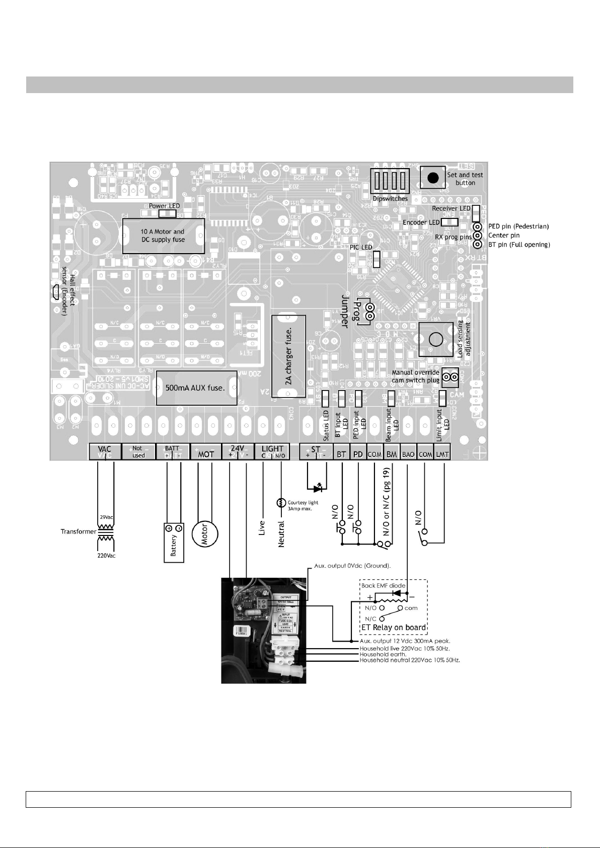
14
Control card layout and wiring.

UMPETHA 082009/072010.014
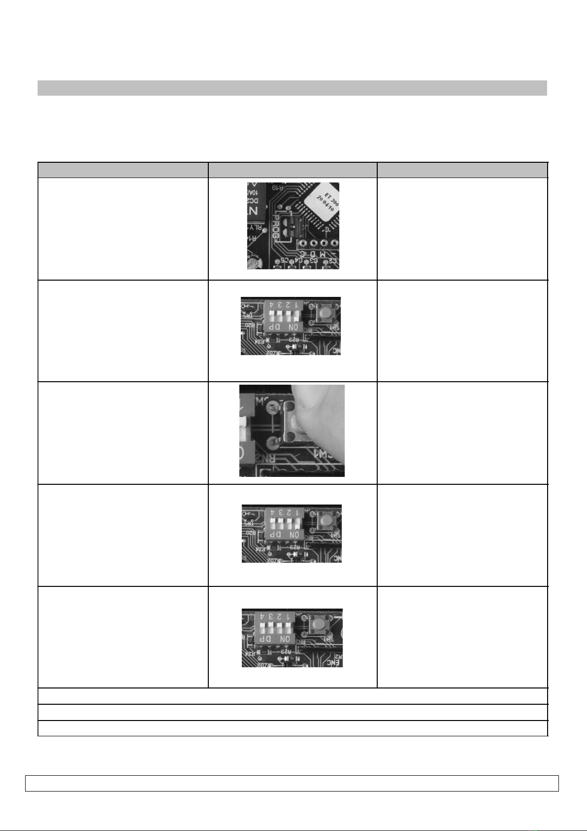
15
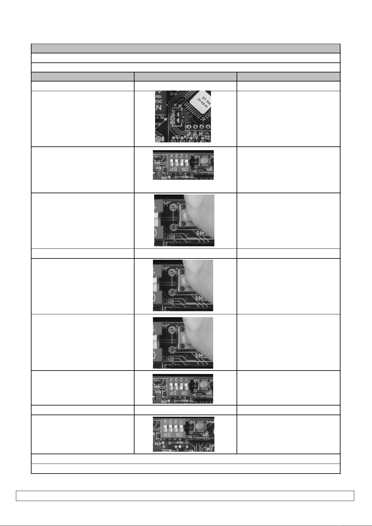
Runtime Setup
Action Response
Gate starts opening
Gate stops and closes
1 beep
Remove program jumper or continue to next feature
Gate stops, 1 beep
Gate will now close correctly
Gate starts opening
Gate stops and closes
Continuous beep off
The run- time routine must be completed before attempting to continue with any other routine! The closed
limit actuator must be installed correctly before starting this routine!
1. Gate midway and engaged.
2. Program jumper on
2 beeps
3. All dip-switches off.
4. Press and release Set button Gate must close. If gate opens first
press and release set button then
see A below!
5. At closed limit
6. Press and release Set button at
required full open position (± 25mm short
of physical stopper)
7. At closed position
*** Changing gate direction if it opens first above.
A) On pressing and releasing the set
button while gate was opening first
B) Dip-switch 3 on
C) Press and release Set button
D) At closed limit
E) Press and release Set button at
required full open position (± 25mm
short of physical stopper)
F) At closed position 1 beep, pause, continuous
beep.
G) Dip-switch 3 off
UMPETHA 082009/072010.014
16
Auto-close time:-
(Default = 15sec.)
NB! The auto-close mode type must be selected after all programming is completed.
(See operating mode selection on page 24)
Action Response
2 beeps
Continuous beep
Continuous beep stops
To change the time again without leav ing programming, repeat from point 2.
Remov e program jumper or continue to another programming option.
NB! This does not activate the Auto-close function. For this see selecting operating modes on page 24
1. Program jumper on
2. Dip-switch 1 on
3. Press and hold Set button,
count beeps for required auto-
close time.
1 beep = 1sec.
2 beeps = 2sec.
....cont
255 beeps = 4.25 min. (Max)
4. Release Set button at
required auto-close time
5. Dip-switch 1 off
UMPETHA 082009/072010.014
17
Pedestrian opening distance and independent pedestrian auto-close time:-
(Default = ± 1m opening and 5sec. auto-close time)
Action Response
Gate midway and engaged
1. Program jumper on 2 beeps
2. Dip-switch 2 on
3. Press and release Set button Gate closes
4. At closed position Gate opens
Gate stops
Gate closes
8. At closed position Continuous beep
9. Dip-switch 2 off Continuous beep stops
To change the pedestrian parameters again without leav ing programming, repeat from point 2.
5. Press and release Set button at
required open distance
6. Press and hold Set button,
count
beeps for auto-close time.
1 beep = 1sec.
2 beeps = 2sec.
....cont
255 beeps = 4.25 min. (Max)
7. Release Set button at required
auto-close time
Remove program jumper or continue to another programming option
UMPETHA 082009/072010.014
18
Changing crawl distance:-
Default: - 350mm
Action Response
2 beeps
Continuous beep
Continuous beep off
To change again without leav ing programming, repeat from point 2.
Remov e program jumper or continue to another programming option
1. Program jumper on
2. Dip-switch 4 on
3. Press and release Set button
Beeps confirm change
1 beep = 350mm
2 beeps = 700mm
4. Dip-switch 4 off

UMPETHA 082009/072010.014
19
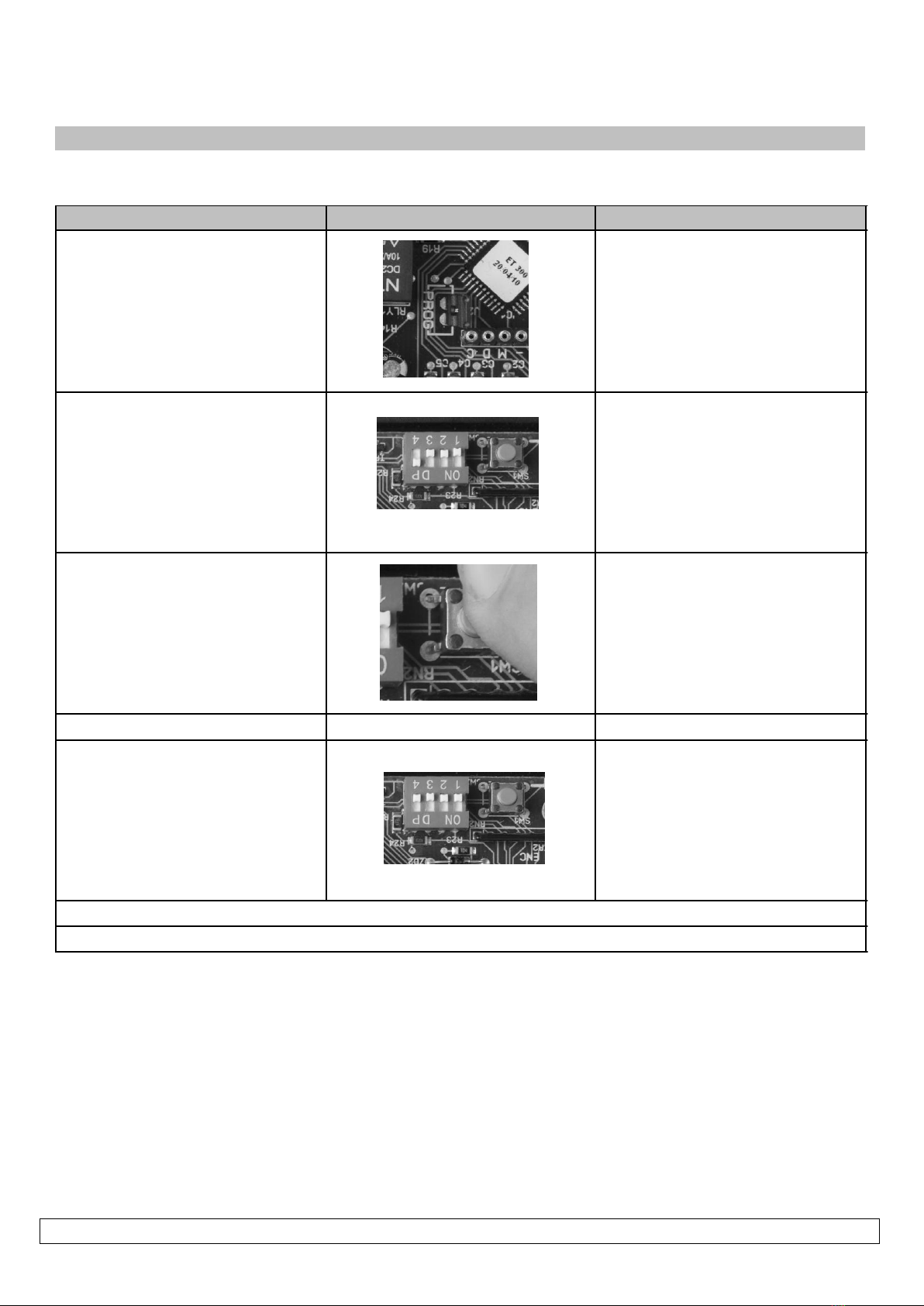
Changing switch type for safety beam input:-
Default:- Normally open
Action Response
2 beeps
After confirmation beeps Continuous beep
Continuous beep off
To change again without leav ing programming, repeat from point 2.
Remov e program jumper or continue to another programming option
1. Program jumper on
2. Dip-switch 1 and 2 on
3. Press and release Set button
Beeps confirm change
1 beep = N/C
2 beeps = N/O (Default)
4. Dip-switch 1 and 2 off

UMPETHA 082009/072010.014
20
Collision/obstruction/hindrance while opening. (All modes)
If a collision, obstruction or hindrance is encountered before the full open position is reached while opening, the gate will stop, back off and
wait for the next trigger input, before closing slowly. The status LED will flash rapidly once stationery after backing off of collision. Closing
trigger clears the status LED indication. For trigger responses see page mode selection on page 23.
Collision/obstruction/hindrance while closing. (All modes)
If a collision, obstruction or hindrance is encountered while closing, the gate will stop and reverse to the fully open position. The status LED
will flash rapidly once stationery after opening away from the collision. The next trigger input starts the gate closing slowly. Closing trigger
clears the status LED indication. For trigger responses see mode selection on page 24.
Multiple collision/obstruction lock-outs. (All modes)
On encountering 4 consecutive obstructions while closing the gate, the UMPETHA will not reverse back to the full open position. The response
will be a 5 sec beep tone, followed by a gentle momentary reverse away from the obstruction. The unit will now begin a mandatory 30sec
lockout whereby the only response to any trigger input will result in a tone so long as the trigger button is held. After 30sec a trigger input will
result in a repeat of the 5 sec beep and the gate opening 1 meter or to the full open position whichever is reached first. The unit will once
again lock out. This time the user must manual release the unit and test the travel by hand before attempting any further automation of the
gate.
The Status LED will flash rapidly throughout this procedure indicating a multiple obstruction lock-out has occurred.
Releasing the gearbox and re-engaging it will clear the LED status and the multiple obstruction lock-out routine.
Collision with closed stopper due to faulty or missing closed limit. (All modes)
If no limit input is made when expected (as calculated by the programmed run time) the UMPETHA will not reverse back to the open position
as it normally would when obstructed. It will however stop at the point of impact with the closed catch and emit a 5sec long beep tone. At
the next valid opening trigger the UMPETHA will re-emit the 5sec long beep tone and only open the gate by ±1 meter. This will allow for the
user to be able to enter the property and manually override the gate. The magnet actuator and limit can now be checked. If not
corrected and further attempts are made to operate the UMPETHA with a faulty closed limit condition the same routine will be repeated on
every operation.
If the user continues to attempt to operate the gate without manually releasing the gearbox while the gate is at the ±1meter position, the
result will only be a repeat of the 5sec beep tone.
Default: - 5KgF max resistance
Action Response
Repeat if necessary.
Adjusting safety obstruction sensing leve l:-
1. Rotate Load pot to new
sensing level.
Clockwise = heav ier gate
resistance
Anti-clockwise = lighter gate
resistance
2. Press and release Set button
to test level
Beeps confirm successful change
1 beep = 5kg resistance (Default)
2 beeps = 10kg resistance
3 beeps = 15kg resistance
4 beeps = 20kg resistance
5 beeps = 22kg resistance (max)
3. After audible confirmation.
Gate runs according to mode
selected.
(See operating mode selection on
page 24)
The load sensing level will also be confirmed audibly on any initial trigger after a full power up or manual
release.
Table of contents
Other E.T. Systems Garage Door Opener manuals


