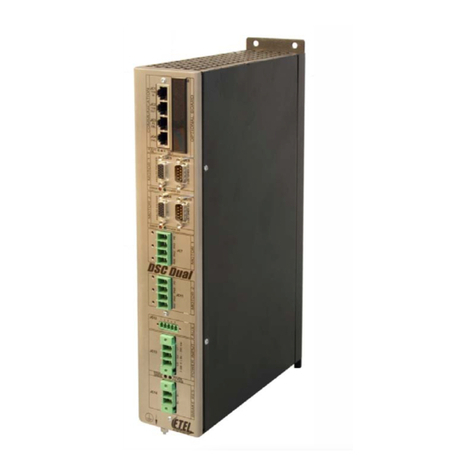
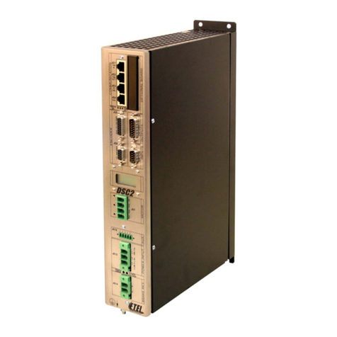
E-Tel DSCDL Series User manual

-~
ARTISAN
®
~I
TECHNOLOGY
GROUP
Your definitive source
for
quality
pre-owned
equipment.
Artisan Technology
Group
Full-service,
independent
repair
center
with
experienced
engineers
and
technicians
on staff.
We
buy
your
excess,
underutilized,
and
idle
equipment
along
with
credit
for
buybacks
and
trade-ins
.
Custom
engineering
so
your
equipment
works
exactly as
you
specify.
•
Critical
and
expedited
services
•
Leasing
/
Rentals/
Demos
• In
stock/
Ready-to-ship
•
!TAR-certified
secure
asset
solutions
Expert
team
ITrust
guarantee
I
100%
satisfaction
All
tr
ademarks,
br
a
nd
names, a
nd
br
a
nd
s a
pp
earing here
in
are
th
e property of
th
e
ir
r
es
pecti
ve
ow
ner
s.
Find the Etel DSCDL332-131 at our website: Click HERE

Copyright ETEL SA. All rights reserved. Reproduction, adaptation or translation of this document is prohibited without prior written permission.
ETEL SA makes no warranty for the use of its products and assume no responsibility for any errors which may appear in this document.
ETEL SA retains the right to make any change to these specifications at any time, without notice.
THE NETHERLANDS
ETEL B.V.
Copernicuslaan 34
NL-6716 BM Ede
Phone : +31 (0)318 495 200
Fax : +31 (0)318 495 210
AMERICAS
ETEL Inc.
333 E. State Parkway,
US - Schaumburg
IL 60173-5337
Phone : +1 847 519 3380
Fax : +1 847 490 0151
E-mail : info@etelusa.com
GERMANY
ETEL GmbH
Schillgasse 14
DE-78661 Dietingen
Phone : +49 (0)741 17453-0
Fax : +49 (0)741 17453-99
HEADQUARTERS
SWITZERLAND
ETEL S.A.
Zone industrielle
CH-2112 Môtiers
Phone : +41 (0)32 862 01 23
Fax : +41 (0)32 862 01 01
http://www.etel.ch
FRANCE
ETEL S.A.
89 rue Henri Rochefort
FR-91025 Evry cedex
Phone : +33 (0)1 64 97 98 05
Fax : +33 (0)1 64 97 30 56
E-mail : etel@etel.fr
ITALY
ETEL S.A.
Piazza della Repubblica 11
IT-28050 Pombia
Phone : +39 0321 958 965
Fax : +39 0321 957 651
E-mail : etel@etelsa.it
SWITZERLAND
ETEL S.A.
Zone industrielle
CH-2112 Môtiers
Phone : +41 (0)32 862 01 33
Fax : +41 (0)32 862 04 12
AUSTRIA (Sales rep)
I+L ELEKTRONIK GmbH
Vibrütteweg 9
AT-6840 Gotzis
Phone : +43 55 23 645 42
Fax : +43 55 23 645 424
E-mail : b.hoerburger@iul-
elektronik.at
ISRAEL (Sales rep)
MEDITAL COMOTECH Ltd
7 Leshem St. - Ramat Siv
IL-49170 Petach tikva
Phone : +972 3 923 3323
Fax : +972 3 923 1666
E-mail : comotech@medital.co.il
Hardware Manual
DSCDL 904 ver. D
DSCDL
Two axes position controller
Two axes position controller
Artisan Technology Group - Quality Instrumentation ... Guaranteed | (888) 88-SOURCE | www.artisantg.com

THIS PAGE IS INTENTIONALLY LEFT BLANK
Artisan Technology Group - Quality Instrumentation ... Guaranteed | (888) 88-SOURCE | www.artisantg.com

ETEL Doc. - Hardware Manual # DSCDL 904 / Ver D / 20/12/05
DSCDL Hardware Manual
Direct Drives & Systems 3
Table of contents
1. Introduction . . . . . . . . . . . . . . . . . . . . . . . . . . . . . . . . . . . . . . . . . . . . . . 6
1.1 Safety . . . . . . . . . . . . . . . . . . . . . . . . . . . . . . . . . . . . . . . . . . . . . . . . . . . . . . . . . . 6
1.2 DSCDL presentation . . . . . . . . . . . . . . . . . . . . . . . . . . . . . . . . . . . . . . . . . . . . . . 7
1.2.1 Working principle . . . . . . . . . . . . . . . . . . . . . . . . . . . . . . . . . . . . . . . . . . . . . . . . . . . . . . . . . 7
1.2.2 Applications . . . . . . . . . . . . . . . . . . . . . . . . . . . . . . . . . . . . . . . . . . . . . . . . . . . . . . . . . . . . . 7
1.2.3 General operating conditions . . . . . . . . . . . . . . . . . . . . . . . . . . . . . . . . . . . . . . . . . . . . . . .7
1.2.4 Transport and storage conditions . . . . . . . . . . . . . . . . . . . . . . . . . . . . . . . . . . . . . . . . . . . 7
1.2.5 Interfaces possibilities . . . . . . . . . . . . . . . . . . . . . . . . . . . . . . . . . . . . . . . . . . . . . . . . . . . . . 7
2. Models characteristics . . . . . . . . . . . . . . . . . . . . . . . . . . . . . . . . . . . . . 9
2.1 Outline and dimensions . . . . . . . . . . . . . . . . . . . . . . . . . . . . . . . . . . . . . . . . . . . 9
2.2 Block schematics . . . . . . . . . . . . . . . . . . . . . . . . . . . . . . . . . . . . . . . . . . . . . . . . 10
2.3 Ratings . . . . . . . . . . . . . . . . . . . . . . . . . . . . . . . . . . . . . . . . . . . . . . . . . . . . . . . . . 11
2.4 Mounting systems – Installation requirements . . . . . . . . . . . . . . . . . . . . . . . . 12
2.5 Ordering information . . . . . . . . . . . . . . . . . . . . . . . . . . . . . . . . . . . . . . . . . . . . . 14
3. Electrical interface . . . . . . . . . . . . . . . . . . . . . . . . . . . . . . . . . . . . . . . . 15
3.1 Encoder connectors . . . . . . . . . . . . . . . . . . . . . . . . . . . . . . . . . . . . . . . . . . . . . . 16
3.1.1 Connectors JC5 and JC6: Position encoders . . . . . . . . . . . . . . . . . . . . . . . . . . . . . . . . . . 16
3.2 Inputs / outputs connectors . . . . . . . . . . . . . . . . . . . . . . . . . . . . . . . . . . . . . . . . 19
3.2.1 Connectors JC12 and JC13: Digital inputs / outputs . . . . . . . . . . . . . . . . . . . . . . . . . . . . 19
3.2.2 Connector JC7: Analog inputs . . . . . . . . . . . . . . . . . . . . . . . . . . . . . . . . . . . . . . . . . . . . . . 20
3.3 Communication connectors . . . . . . . . . . . . . . . . . . . . . . . . . . . . . . . . . . . . . . . 22
3.3.1 Connector JC1: Turbo-ETEL-Bus input . . . . . . . . . . . . . . . . . . . . . . . . . . . . . . . . . . . . . . . 23
3.3.2 Connector JC2: Turbo-ETEL-Bus output . . . . . . . . . . . . . . . . . . . . . . . . . . . . . . . . . . . . . . 23
3.3.3 Connector JC3: ETEL-Bus-Lite2 serial communication . . . . . . . . . . . . . . . . . . . . . . . . . . 23
3.3.4 Connector JC4: Download key . . . . . . . . . . . . . . . . . . . . . . . . . . . . . . . . . . . . . . . . . . . . . . 24
3.4 Motor connectors . . . . . . . . . . . . . . . . . . . . . . . . . . . . . . . . . . . . . . . . . . . . . . . . 25
3.4.1 Connectors JC8 and JC9: Motor connection . . . . . . . . . . . . . . . . . . . . . . . . . . . . . . . . . . . 25
3.5 Power connector . . . . . . . . . . . . . . . . . . . . . . . . . . . . . . . . . . . . . . . . . . . . . . . . . 26
3.5.1 Connector JC10: Power supply input . . . . . . . . . . . . . . . . . . . . . . . . . . . . . . . . . . . . . . . . . 26
3.6 Optional boards connector . . . . . . . . . . . . . . . . . . . . . . . . . . . . . . . . . . . . . . . . 26
3.6.1 Connector JC11: Depends on the type of board . . . . . . . . . . . . . . . . . . . . . . . . . . . . . . . . 26
3.7 Cables . . . . . . . . . . . . . . . . . . . . . . . . . . . . . . . . . . . . . . . . . . . . . . . . . . . . . . . . . 27
3.7.1 Manufacturing . . . . . . . . . . . . . . . . . . . . . . . . . . . . . . . . . . . . . . . . . . . . . . . . . . . . . . . . . . . . 27
3.8 Axis number selection . . . . . . . . . . . . . . . . . . . . . . . . . . . . . . . . . . . . . . . . . . . . 28
3.9 LEDs meaning . . . . . . . . . . . . . . . . . . . . . . . . . . . . . . . . . . . . . . . . . . . . . . . . . . . 29
Artisan Technology Group - Quality Instrumentation ... Guaranteed | (888) 88-SOURCE | www.artisantg.com

DSCDL Hardware Manual
4Direct Drives & Systems
ETEL Doc. - Hardware Manual # DSCDL 904 / Ver D / 20/12/05
THIS PAGE IS INTENTIONALLY LEFT BLANK
Artisan Technology Group - Quality Instrumentation ... Guaranteed | (888) 88-SOURCE | www.artisantg.com

ETEL Doc.- Hardware Manual # DSCDL 904 / Ver D / 20/12/05
DSCDL Hardware Manual
Direct Drives & Systems 5
Record of revisions, document # DSCDL 904 x
Documentation concerning the DSCDL:
• DSCDL Hardware Manual (Specifications & electrical interfaces) # DSCDL 904 D
• Operation & Software Manual (DSCDL's setup, use and programming) # DSC2P 903 x
• DSO-RAC2 Hardware Manual (DSO-RAC2 principle) # DSORAC2 904 x
• EBL2 Communication Manual (EBL2 principle, message mapping) # EBL2 908 x
• DSCDL Service Manual (Maintenance of the fuses) # DSCDL 905 x
Document revisions
Issue (x) Date Modified
Ver A 14.10.02 First version
Ver B 25.11.03
Updated version
- New hardware version
- Additional safety precautions in accordance with the UL & CE standards
Ver C 16.04.04
Updated version
- New hardware version (DSCDL3xx-xxx)
- EnDat encoder
Ver D 20.12.05 Updated version
- Additional detailed descriptions
Artisan Technology Group - Quality Instrumentation ... Guaranteed | (888) 88-SOURCE | www.artisantg.com

DSCDL Hardware Manual
6Direct Drives & Systems
ETEL Doc. - Hardware Manual # DSCDL 904 / Ver D / 20/12/05
1. Introduction
This document concerns a two axes digital position controller of ETEL's DSCxx family: the DSCDL also called
'controller' in this document.
The purpose of this manual is to give details regarding the specifications, installation, interfacing and hardware
items. All details for proper connections (power supply, motor, encoder connection, etc...) are provided herein.
Detailed information concerning the programming of the controller is provided in the corresponding 'Operation
& Software Manual'.
The information given in this manual is valid for type # D S C D L 3 x x - x x x C and later.
Remark: The updates between two successive versions are highlighted with a modification stroke in the
margin of the manual.
1.1 Safety
Please, read all the safety precautions listed in this manual before handling the
DSCDL:
• Never use the DSCDL for purposes other than those described in this manual.
• A competent and trained technician must install and operate the DSCDL, in accordance with all specific
regulations of the respective country concerning both safety and EMC aspects.
• Troubleshooting and servicing are permitted only by ETEL's technicians and agreed distributors.
• Operating the DSCDL will make the motor move. Keep away from all moving parts to avoid
injuries!
• The safety symbols placed on the DSCDL or written in the manuals must be respected.
• If the DSCDL is integrated into a machine, the manufacturer of this machine must establish that it fulfils the
89/336/EEC directive on EMC before operating the controller.
Caution: Signals a danger for the DSCDL. Can be destructive for the material.
A danger for the operator can result from this.
Caution: Indicates electrostatic discharges (ESD), dangerous for the DSCDL.
The components must be handled in an ESD protected environment only.
Artisan Technology Group - Quality Instrumentation ... Guaranteed | (888) 88-SOURCE | www.artisantg.com

ETEL Doc.- Hardware Manual # DSCDL 904 / Ver D / 20/12/05
DSCDL Hardware Manual
Direct Drives & Systems 7
1.2 DSCDL presentation
1.2.1 Working principle
The DSCDL is a digital position controller. It has been designed for direct drive applications. It includes on a
single board, the control circuits, the power stage and all the necessary interfaces for the communication, the
encoders and the inputs/outputs for two motors.
1.2.2 Applications
The DSCDL can drive two single or/and two-phase motors. The DSCDL can drive brushless and DC motors.
They must also be implemented with analog (incremental or absolute (EnDat 2.1)) or TTL encoders available
on the market. It is also possible to drive stepper motors in open loop (no need of encoder in this case) with
firmware from version 1.06A.
1.2.3 General operating conditions
The DSCDL is designed to operate in a non-aggressive and clean environment, with a humidity rate ranging
between 10% and 85%, an altitude < 2000m (6562 ft), and a temperature ranging between + 15°C (59°F) and
+ 30°C (86°F). The DSCDL must be connected to an electrical network of overvoltage category 2 (refer to EN
50178 and UL 804 standards for more information). The electronics must be in an enclosure respecting a
pollution degree of 2 (refer to UL 508C and EN 50178 standards for more information). The DSCDL is not
designed or intended for use in the on-line control of air traffic, aircraft navigation and communications as well
as critical components in life support systems or in the design, construction, operation and maintenance of any
nuclear facility.
1.2.4 Transport and storage conditions
During the transport and the storage, the controller must remain inside its original packaging. The transport
conditions must respect the class 2K3 of the IEC 60721-3-2 standard (temperature between -25°C and +70°C,
and humidity < 95% without condensation) and the storage conditions must respect the class 1K2 of the IEC
60721-3-1 standard (temperature between +5°C and +45°C, and humidity between 5 and 85% without
condensation).
1.2.5 Interfaces possibilities
Motor and its position encoder
To control the position (in closed loop) of a rotary and/or linear motor, the DSCDL needs a signal coming from
an analog (incremental or absolute (EnDat 2.1)) or a TTL encoder linked to this or these motor(s). It is also
possible to drive stepper motors in open loop (no need of encoder in this case).
Communication
The user can set the DSCDL with a PC (Win 9x/2000/NT/XP) using the ETEL Tools (ETT) software through
the ETEL-Bus-Lite2 (RS232 / RS422) communication port. Refer to the 'EBL2 Communication Manual' for
more information.
The DSCDL also includes ETEL's Turbo-ETEL-Bus (TEB) which is a high speed field bus based on an Ethernet
100 Mbps chip. It includes all features to interpolate complex movements with several synchronized DSCDLs,
if ETEL's DSMAX motion controller is installed in a PC and linked to the TEB. If ETEL Tools is installed on the
same PC than the DSMAX (or DSTEB) board, all the DSCDLs can be set through the TEB. The user can 'daisy
chain' up to 31 nodes on the TEB (15 DSCDLs (30 axes) and one DSMAX (or DSTEB) board).
Caution: The TEB is not compatible with Ethernet boards available on the market. Therefore, do not
connect the TEB on the Ethernet port of your PC.
Inputs / outputs
The customer's inputs / outputs are digital signals coming from a CNC machine-tool, a PLC or a joystick for
example (refer to the connection diagram next page).
The electrical interface details are given in §3.
Artisan Technology Group - Quality Instrumentation ... Guaranteed | (888) 88-SOURCE | www.artisantg.com

DSCDL Hardware Manual
8Direct Drives & Systems
ETEL Doc. - Hardware Manual # DSCDL 904 / Ver D / 20/12/05
Connection diagram:
Rotary or linear motor for M2
Rotary or linear motor for M1
Rotary / linear incremental or
absolute (EnDat 2.1) analog /
TTL encoder for motor M1
Communication with PC/CNC/
PLC (setup with ETT or ComET
software or 'host' commands)
Customers inputs / outputs
(CNC, PLC or joystick ...)
ETEL's DSCDLs
15 slaves (max)
+ DSMAX (or DSTEB)
External
power supply
Optional boards
Rotary / linear incremental or
absolute (EnDat 2.1) analog /
TTL encoder for motor M2
Artisan Technology Group - Quality Instrumentation ... Guaranteed | (888) 88-SOURCE | www.artisantg.com

ETEL Doc.- Hardware Manual # DSCDL 904 / Ver D / 20/12/05
DSCDL Hardware Manual
Direct Drives & Systems 9
2. Models characteristics
Two models of DSCDL are available, according to the needs:
1. Rack format with plate heat sink
2. Rack format with extruded heat sink
These 2 models are dedicated to be mounted inside a standard 6U rack case. They do not include any power
supply board and need to be powered through their DC power connector (JC10) by an external power supply.
There are two different sizes of DSCDL rack format: the DSCDL3x1-xxx (10F wide) and the DSCDL3x2-xxx
(14F wide).
2.1 Outline and dimensions
Refer to the following chapters for details about the connectors:
JC1 (see §3.3.1)JC5(see§3.1.1)JC8(see§3.4.1)JC11(see§3.6.1)
JC2 (see §3.3.2)JC6(see§3.1.1)JC9(see§3.4.1)JC12(see§3.2.1)
JC3 (see §3.3.3)JC7(see§3.2.2) JC10 (see §3.5.1)JC13(see§3.2.1)
JC4 (see §3.3.4)
261.80
50.60
Standard 6U 10F
Unit: [mm]
Weight: 1.1 Kg
164.00
164.00
261.80
70.80
Standard 6U 14F
Unit: [mm]
Weight: 2 Kg
Artisan Technology Group - Quality Instrumentation ... Guaranteed | (888) 88-SOURCE | www.artisantg.com

DSCDL Hardware Manual
10 Direct Drives & Systems
ETEL Doc. - Hardware Manual # DSCDL 904 / Ver D / 20/12/05
2.2 Block schematics
In the DSCDL rack format, all parts are on a single board: the servo board. They need to be powered by an
external power supply. This power supply must meet all the specifications written in §2.3.
On the servo board, the power part and the control part are not galvanically separated. The inputs and outputs
are insulated from the control part by opto-couplers.
Remark: M1 and M2 represent the motor 1 and the motor 2 respectively.
Caution: The GND (marked 0V) is internally connected to the DSCDL front panel which is
connected to the ground (PE).
SERVO BOARD
A / D conversion
V+
GND
M1
P1+
+2.5
/3.3V
DIP switch
AXIS #
M1
M2
V-
GND
Vaux
DC
M
O
T
O
R
O
U
T
P
U
T
JC8
JC9
P1-
P2+
P2-
M2
PE
P1+
P1-
P2+
P2-
PE
PE
E
X
T
E
R
N
A
L
P
O
W
E
R
S
U
P
P
L
Y
Fuse Fuse Fuse
Fuse
Fuse
Fuse
GND GND GND
DC
Thermostat
Digital control
0V+5V
Linear power stage
Linear power stage
ETEL-Bus-Lite2
IN / OUT
TEB
IN / OUT
JC1 to 3 JC5 JC6
Analog/EnDat 2.1/
TTL encoder input
M2
Analog/EnDat 2.1/
TTL encoder input
M1
Digital
inputs M1
Digital
outputs M1
JC12 JC13
Digital
inputs M2
Digital
outputs M2
Optional
board
DSO-HIO
JC11
JC7
Analog
input M1
Analog
input M2
Artisan Technology Group - Quality Instrumentation ... Guaranteed | (888) 88-SOURCE | www.artisantg.com

ETEL Doc.- Hardware Manual # DSCDL 904 / Ver D / 20/12/05
DSCDL Hardware Manual
Direct Drives & Systems 11
2.3 Ratings
There is one type of 10F wide rack format (the DSCDL331-xxx) and one type of 14F wide rack format (the
DSCDL332-xxx).
All the specifications are given for an ambient temperature ranging from +15°C (59°F) to +30°C (86°F)
and with an air flow of 2 m/s (400 LFM) inside the rack case:
Remark: The values given in the following table are valid for each motor.
(1): Continuous current can be reached only with forced air cooling (external fan necessary: refer to §2.4)
(2): With optional board mounted on the DSCDL, no external device connected to the I/O. The current can
change depending on the type(s) of encoder(s) used.
Remark: The values given in the above-mentioned table are given for a sinusoidal output current with a
frequency higher than 0.5 Hz. The losses induced by a AC current are shared between the
transistors. A DC current heat up only some of the power elements and can induce their
breakdown after 10 minutes if the current is near the maximum full load.
DSCDL POWER FEATURES
Characteristics DSCDL331-13x DSCDL332-13x
Output to the motor
(per motor)
Voltage ±36VDC
Current range on product label 1.2 Arms / 2.8 Arms (1s) 2.4 Arms / 3.6 Arms (1s)
One-phase motor
Max. full load current
1.5(1) A
(1.06 Arms)
2.3(1) A
(1.62 Arms)
One-phase motor
Max overload current during 2 seconds
4(1) A
(2.82 Arms)
5(1) A
(3.53 Arms)
Two-phase motor
Max. full load current
1.7(1) A
(1.2 Arms)
3.5(1) A
(2.47 Arms)
Two-phase motor
Max overload current during 2 seconds
4(1) A
(2.82 Arms)
5(1) A
(3.53 Arms)
Power supply input
DC voltage ±36VDC
Max. DC current (at ±36VDC) 5A(2) 10 A(2)
Auxiliary supply input
DC voltage +15VDC to +36VDC
Max. current at 15VDC 1.5 A(2)
Max. current at 36VDC 750 mA(2)
Maximum current measurable by the controller 6.25 A 6.25 A
DSCDL CONTROL FEATURES
General
Motion profile and command
management sampling time 500 µs
Current loop sampling time 13.89 µs (72 KHz)
Position loop sampling time 55.55 µs (18 KHz)
Motion profiles Trapezoidal / S-curve / Sine / look-up table /
interpolated (DSMAX)
32 bits floating point DSP Dual SHARC Digital Signal Processor
Standard
interfaces
ETEL-BUS-LITE 2 host (PC) communication RS232 or RS422 / 115'200 bps
Turbo-ETEL-Bus multi-axis communication 100 Mbps (based on Ethernet components)
Position
encoders
interfaces
EnDat 2.1 compatible RS485
Analog 1 Vptp Max. 400KHz in. / up to 32768 (x4) interpolation factor
TTL encoder possible Max 400KHz (period frequency)
Encoder limit switch (EHO + ELS) TTL signal
Artisan Technology Group - Quality Instrumentation ... Guaranteed | (888) 88-SOURCE | www.artisantg.com

DSCDL Hardware Manual
12 Direct Drives & Systems
ETEL Doc. - Hardware Manual # DSCDL 904 / Ver D / 20/12/05
2.4 Mounting systems – Installation requirements
The DSCDL rack formats are dedicated to be mounted inside a rack case system.
Warning: The rack case with the controllers has the following electrical safety degree: IP 20
(according to EN 60529 standard). To respect this degree, each empty slot (if a
controller is not present in the rack case) must be closed by a front panel.
The rack case must be in an enclosure respecting a pollution degree of 2 (refer to
UL 508C and EN 50178 standards for more information).
The rack formats are mounted vertically inside a rack case. Here is an example:
In the solution outlined above, height DSCDL3x1-xxx are present in a rack case (powered by an external power
supply not included in the above-mentioned drawing).
The rack case systems should be protected against any splashes of liquid and any contacts with smoke and
dust. It must be installed inside a closed cabinet and screwed on a metallic plate, connected to the ground,
where no vibration will occur.
U s e r ' s
inputs / outputs
Digital input, insulated 4 per motor
(+8 with DSO-HIO optional board but shared between both motors)
Digital output. insulated 2 per motor
(+8 with DSO-HIO optional board but shared between both motors)
Analog input 1 per motor (+4 depending on the DSO-HIO optional board version
but shared between both motors)
Analog output 0 (+4 depending on the DSO-HIO optional board version but shared
between both motors)
Software /
programmability
ETEL Tools software for setting / monitoring Windows 9x / XP / 2000 / NT
DLL files (C / C++ / VB / LV) Windows 9x / XP / 2000 / NT / QNX4 / QNX6
User's programmable sequence 4096 lines per axis
Firmware update RS232 / Turbo-ETEL-Bus
DSCDL CONTROL FEATURES
465.10
265.90
261.80 (6U)
426.72 (84F)
483.00 (19'')
190.50
Rack case depth: 240 (without the depth of the handle) Unit: [mm]
Artisan Technology Group - Quality Instrumentation ... Guaranteed | (888) 88-SOURCE | www.artisantg.com

ETEL Doc.- Hardware Manual # DSCDL 904 / Ver D / 20/12/05
DSCDL Hardware Manual
Direct Drives & Systems 13
Fresh air is necessary to cool the controllers inside the rack case (the flow depends on the user application). It
is recommended to install fans in the cabinet to guarantee an air flow (the fan power depends on the user
application). Caution: some fans may perturb the current measurement of the controller if they are too
close to the rack case. If this problem occurs, use another type of fan or increase the distance between
the fan and the rack case while ensuring the air flow mentioned hereafter. The air flow inside ETEL's rack
cases with fans is equal to minimum 2 m/s (400 LFM) (the fans, used with the rack case, have an air flow of
94.2 CFM). Refer to the 'DSO-RAC2 Hardware Manual' for more information about the rack case.
This drawing shows a rack case with rack formats, inside a cabinet:
The following distances are recommended: A = 100 [mm] (drawing out of scale).
Dust filter
Artisan Technology Group - Quality Instrumentation ... Guaranteed | (888) 88-SOURCE | www.artisantg.com

DSCDL Hardware Manual
14 Direct Drives & Systems
ETEL Doc. - Hardware Manual # DSCDL 904 / Ver D / 20/12/05
2.5 Ordering information
Here is the ordering information describing the meaning of each digit present on the label of the DSCDL:
Remark: Not all the combinations are possible.
D S C D L331-111X-0 0 0
Family product:
DSCDL: Linear position controller
Encoder type:
3 = Analog (1Vptp) or absolute (EnDat 2.1) or TTL
Power output:
3 = 1.2 Arms / 2.8 Arms (1s) for 10F rack
2.4 Arms / 3.6 Arms (1s) for 14F rack
Assembly:
1 = Rack format with plate heat sink and frontplate of 10F
2 = Rack format with extruded heat sink and frontplate of 14F
Reserved for future use
Power supply input:
3 = ±36VDC
Standard option:
1 = Not UL recognized
2 = UL recognized
By default, the DSCDL3 is delivered without UL recognition
Hardware version
Customer modification
000 means ’standard product’
Artisan Technology Group - Quality Instrumentation ... Guaranteed | (888) 88-SOURCE | www.artisantg.com

ETEL Doc.- Hardware Manual # DSCDL 904 / Ver D / 20/12/05
DSCDL Hardware Manual
Direct Drives & Systems 15
3. Electrical interface
This chapter describes the pin assignment for every connector. More detailed explanations for proper
connections are given in each case.
There are six groups of connectors, according to their function:
Encoders connectors (see §3.1).
Inputs / outputs connectors (see §3.2).
Communication connectors (see §3.3).
Motor connectors (see §3.4).
Power connector (see §3.5).
Optional boards connector (see §3.6).
Caution: Before connecting or disconnecting a cable on one of these connectors or touching
the controller, turn off all the power supplies and wait 2 minutes to allow the
internal DC bus capacitors to discharge.
Caution: All the inputs/outputs cables must be insulated (no contact) from the power and
the mains.
The inputs and outputs must be connected to an Extra Low Voltage circuit only
(SELV).
Most inputs and outputs are not galvanically insulated from the GND.
The motor connectors must always be correctly screwed onto the DSCDL.
Caution: All the connectors must be handled in an ESD protected environment, only.
Remark: In the next paragraphs, connectors with male pins are indicated with the •symbol (full), and
female pins are represented with the οsymbol (empty).
Artisan Technology Group - Quality Instrumentation ... Guaranteed | (888) 88-SOURCE | www.artisantg.com

DSCDL Hardware Manual
16 Direct Drives & Systems
ETEL Doc. - Hardware Manual # DSCDL 904 / Ver D / 20/12/05
3.1 Encoder connectors
3.1.1 Connectors JC5 and JC6: Position encoders
Caution: The encoder cable(s) must be insulated (no contact) from the power and the mains.
The inputs and outputs of this connector are not galvanically insulated from the GND.
The inputs and outputs must be connected to an Extra Low Voltage circuit only
(SELV).
Caution: The encoder connectors must be handled in an ESD protected environment, only.
Remark: The encoder cable(s) connected to the DSCDL must be shielded (see §3.7.1).
3 different types of encoder can be connected to each encoder connector of a DSCDL: either an
incremental analog encoder 1 Vptp, or an analog absolute encoder (EnDat 2.1) or a TTL encoder.
3.1.1.1 Incremental analog encoder (1 Vptp)
The incremental analog encoder has 1Vptp signals with a load resistor R0=120Ω. It determines the motor
position thanks to two sinusoidal signals with a 90° phase-shift (sine and cosine). A third signal, the index (also
called reference mark) gives the absolute motor position:
D-SUB, 15 pins, high density, female
ENCODER Pin # Signal Function Interface
1 Reserved Do not connect
2 Reserved Do not connect
3 Reserved Do not connect
4 +5VDC Encoder supply output (protected by fuse F2 of 1A)
5 GND Encoder supply output (0V)
6 COS - Cosine - signal input
7 SIN - Sine - signal input
8 IDX - Index - signal input
9 Reserved Do not connect
10 EHO Encoder home switch input (TTL signal)
11 ELS Encoder limit switch input (TTL signal)
12 GND Encoder supply output (0V)
13 COS + Cosine + signal input
14 SIN + Sine + signal input
15 IDX + Index + signal input
Position
Position
Position
Sine
Cosine
Index
+0.5V
+0.5V
-0.5V
-0.5V
0V
0V
Reference mark acquisition zone
ENCODER
1
5
15
11
JC5 & JC6
COS +
SIN +
IDX +
COS -
SIN -
IDX - R
R
R0
C
C
DSCDL
Artisan Technology Group - Quality Instrumentation ... Guaranteed | (888) 88-SOURCE | www.artisantg.com

ETEL Doc.- Hardware Manual # DSCDL 904 / Ver D / 20/12/05
DSCDL Hardware Manual
Direct Drives & Systems 17
Remark: The +5VDC encoder supply output is protected by the fuse F2 (1A) on JC5 and JC6.
JC5 is used to connect the encoder of motor 1 and JC6 for the one of motor 2.
Refer to the corresponding 'Operation & Software Manual' for more information about the use
of the EHO and ELS signals.
3.1.1.2 Absolute analog encoder (EnDat 2.1)
The EnDat 2.1 is an absolute encoder. It has 1Vptp signals with a load resistor R0=120Ω. Its signals are
similar to the incremental encoders (without the index), but it additionally includes a RS485 serial link (EIA
standard, EnDat 2.1 interface) for the absolute position measure: EDT (serial data) and ECL (clock). The ECL
(clock) signal is received from the DSCDL. From its first falling edge (latch signal), the absolute position will
be defined within one incremental signal period (depends on the encoder type).
Remark: The +5VDC encoder supply output is protected by the fuse F2 (1A) on JC5 and JC6.
The cable used with an absolute analog encoder (EnDat 2.1) must have power wires with a
minimum diameter to guarantee a sufficient voltage at the terminals of the encoder (refer to the
data sheet of the encoder for more information).
JC5 is used to connect the encoder of motor 1 and JC6 for the one of motor 2.
3.1.1.3 TTL encoder
Caution: It is possible to connect a TTL encoder on this connector but the input frequency is
limited to 400KHz because the interface is an analog one.
TTL encoders measure the motor position with 2 phase-shifted TTL signals. Each change of state of one of the
signals corresponds to an increment of the motor position. A third signal (index) gives the motor absolute
position. The encoder TTL signals have to be compatible with the EIA standard RS422. These signals have
the following form:
D-SUB, 15 pins, high density, female
ENCODER Pin # Signal Function Interface
1EDT+
EnDat serial data I/O + / RS485
2ECL+
EnDat clock output + / RS485
3ECL-
EnDat clock output - / RS485
4+5VDC
Encoder supply output (protected by fuse F2 of 1A)
5GND
Encoder supply output (0V)
6COS-
Cosine - signal input
7 SIN - Sine - signal input
8Reserved
Do not connect
9EDT-
EnDat serial data I/O - / RS485
10 Reserved Do not connect
11 Reserved Do not connect
12 GND Encoder supply output (0V)
13 COS + Cosine + signal input
14 SIN + Sine + signal input
15 Reserved Do not connect
ENCODER
1
5
15
11
JC5 & JC6
COS +
SIN +
COS -
SIN -
R
R
R0
C
C
DSCDL
Artisan Technology Group - Quality Instrumentation ... Guaranteed | (888) 88-SOURCE | www.artisantg.com

DSCDL Hardware Manual
18 Direct Drives & Systems
ETEL Doc. - Hardware Manual # DSCDL 904 / Ver D / 20/12/05
The +5V encoder supply output is protected by fuse F2 (1A) on JC5 and JC6.
Remark: JC5 is used to connect the encoder of motor 1 and JC6 for the one of motor 2.
Refer to the corresponding 'Operation & Software Manual' for more information about the use
of the EHO and ELS signals.
D-SUB, 15 pins, high density, female
ENCODER Pin # Signal Function Interface
1 Reserved Do not connect
2 Reserved Do not connect
3 Reserved Do not connect
4+5V
Encoder supply output (protected by fuse F2 of 1A)
5GND
Encoder supply output (0V)
6UA2-
TTL2 - signal input
7UA1-
TTL1 - signal input
8UA0-
TTL0 - signal input
9 Reserved Do not connect
10 EHO Encoder home switch input (TTL signal)
11 ELS Encoder limit switch input (TTL signal)
12 GND Encoder supply output (0V)
13 UA2 + TTL2 + signal input
14 UA1 + TTL1 + signal input
15 UA0 + TTL0 + signal input
Signal TTL 1 (UA1)
Signal TTL 2 (UA2)
Index TTL 0 (UA0)
Reference mark acquisition zone
ENCODER
1
5
15
11
JC5 & JC6
COS +
SIN +
IDX +
COS -
SIN -
IDX - R
R
R=120Ω
C
C
DSCDL
Artisan Technology Group - Quality Instrumentation ... Guaranteed | (888) 88-SOURCE | www.artisantg.com

ETEL Doc.- Hardware Manual # DSCDL 904 / Ver D / 20/12/05
DSCDL Hardware Manual
Direct Drives & Systems 19
3.2 Inputs / outputs connectors
3.2.1 Connectors JC12 and JC13: Digital inputs / outputs
Caution: The digital inputs/outputs cable must be insulated (no contact) from the power and
the mains.
The digital inputs and outputs must be connected to an Extra Low Voltage circuit only
(SELV).
The digital inputs and outputs are galvanically insulated from the GND by
opto-couplers.
Caution: These connectors must be handled in an ESD protected environment, only.
Remark: The digital inputs/outputs cable(s) connected to the DSCDL must be shielded (see §3.7.1).
The DSCDL has 4 digital inputs (DIN1, DIN2, DIN9 and DIN10) and 2 digital outputs (DOUT1 and DOUT2) per
motor. Every digital input and output is opto-coupled. DIN2 is opto-coupled through a high speed opto-
couplers (100 ns).
Only inputs and outputs interface is considered here. Refer to the corresponding 'Operation & Software
Manual' for more information about the use of these inputs and outputs.
3.2.1.1 Digital inputs
The digital inputs switch to ’1’ when a voltage ranging between +12VDC and +28VDC is applied between pins
DIN+ of the corresponding input and GNDext.
The digital inputs switch to ‘0’ when a zero voltage is applied between pins DIN+ of the corresponding input
and GNDext.
Remark: When using an external ‘positive limit switch’, connect it to DIN10.
When using an external ‘negative limit switch’, connect it to DIN9.
When using an external ‘home switch’, connect it to DIN2.
The auxiliary supply can be external to the controller, as shown below:
3.2.1.2 Digital outputs
To use a digital output, a voltage should previously be supplied to the external auxiliary supply (+Vext). This
voltage should range between +12VDC and +28VDC. The maximum total current provided by the digital
outputs is limited to 500 mA (limited by fuse F1).
It is recommended to use an external auxiliary supply (+Vext) as shown below (in this case, the logical value
‘1’ will correspond to +Vext and ‘0’ to GND ext).
Remark: This diagram shows the use of DOUT1, but it is the same with the DOUT2
External
supply
DSCDL
DIN1 +
GNDext
1
5
DSCDL
+Vext
(+12VDC → +28VDC)
+Vext
DOUT1
GNDext
6
7
5DOUT1
Artisan Technology Group - Quality Instrumentation ... Guaranteed | (888) 88-SOURCE | www.artisantg.com
This manual suits for next models
3
Table of contents
Other E-Tel Controllers manuals
Popular Controllers manuals by other brands

Segway
Segway InfoKey installation instructions
Philips
Philips Dynalite DDBC516FR installation manual

Contemporary Research
Contemporary Research ICC1-232 Specifications
Whelen Engineering Company
Whelen Engineering Company Wireless Traffic Advisor Installation guides
LS
LS XEL-BSSRT/F/H installation guide
dooch
dooch Q-Drive NQ-0400-S user guide
