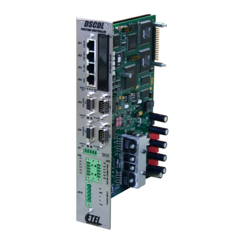
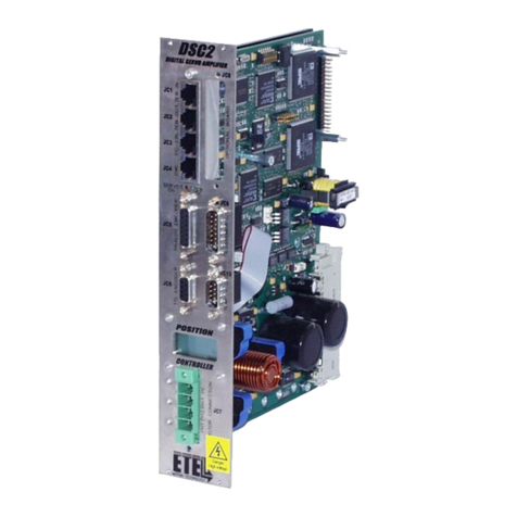
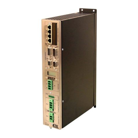
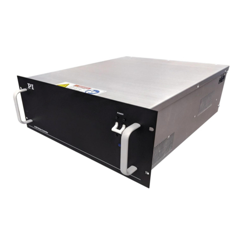
E-Tel DSC Series User manual

-~
ARTISAN
®
~I
TECHNOLOGY
GROUP
Your definitive source
for
quality
pre-owned
equipment.
Artisan Technology
Group
Full-service,
independent
repair
center
with
experienced
engineers
and
technicians
on staff.
We
buy
your
excess,
underutilized,
and
idle
equipment
along
with
credit
for
buybacks
and
trade-ins
.
Custom
engineering
so
your
equipment
works
exactly as
you
specify.
•
Critical
and
expedited
services
•
Leasing
/
Rentals/
Demos
• In
stock/
Ready-to-ship
•
!TAR-certified
secure
asset
solutions
Expert
team
ITrust
guarantee
I
100%
satisfaction
All
tr
ademarks,
br
a
nd
names, a
nd
br
a
nd
s a
pp
earing here
in
are
th
e property of
th
e
ir
r
es
pecti
ve
ow
ner
s.
Find the Etel DSCDP131-111D at our website: Click HERE

Copyright ETEL SA. All rights reserved. Reproduction, adaptation or translation of this document is prohibited without prior written permission.
ETEL SA retains the right to make any change to these specifications at any time, without notice.
DSCDP Hardware Manual
DSCDP-
Hardware-VerG
Two axes position controller
Two axes position controller
Artisan Technology Group - Quality Instrumentation ... Guaranteed | (888) 88-SOURCE | www.artisantg.com

THIS PAGE IS INTENTIONALLY LEFT BLANK
Artisan Technology Group - Quality Instrumentation ... Guaranteed | (888) 88-SOURCE | www.artisantg.com

ETEL Doc. - Hardware Manual # DSCDP / Ver G / 6/1/11
DSCDP Hardware Manual 3
Table of contents
1. Introduction . . . . . . . . . . . . . . . . . . . . . . . . . . . . . . . . . . . . . . . . . . . . . . 6
1.1 Safety . . . . . . . . . . . . . . . . . . . . . . . . . . . . . . . . . . . . . . . . . . . . . . . . . . . . . . . . . . 6
1.2 DSCDP presentation . . . . . . . . . . . . . . . . . . . . . . . . . . . . . . . . . . . . . . . . . . . . . . 7
1.2.1 Working principle . . . . . . . . . . . . . . . . . . . . . . . . . . . . . . . . . . . . . . . . . . . . . . . . . . . . . . . . . 7
1.2.2 Applications . . . . . . . . . . . . . . . . . . . . . . . . . . . . . . . . . . . . . . . . . . . . . . . . . . . . . . . . . . . . . 7
1.2.3 General operating conditions . . . . . . . . . . . . . . . . . . . . . . . . . . . . . . . . . . . . . . . . . . . . . . .7
1.2.4 Transport and storage conditions . . . . . . . . . . . . . . . . . . . . . . . . . . . . . . . . . . . . . . . . . . . 7
1.2.5 Interfaces possibilities . . . . . . . . . . . . . . . . . . . . . . . . . . . . . . . . . . . . . . . . . . . . . . . . . . . . . 7
2. Models characteristics . . . . . . . . . . . . . . . . . . . . . . . . . . . . . . . . . . . . . 10
2.1 Rack format . . . . . . . . . . . . . . . . . . . . . . . . . . . . . . . . . . . . . . . . . . . . . . . . . . . . . 10
2.1.1 Outline and dimensions . . . . . . . . . . . . . . . . . . . . . . . . . . . . . . . . . . . . . . . . . . . . . . . . . . . . 10
2.1.2 Block schematics . . . . . . . . . . . . . . . . . . . . . . . . . . . . . . . . . . . . . . . . . . . . . . . . . . . . . . . . . 11
2.1.3 Ratings . . . . . . . . . . . . . . . . . . . . . . . . . . . . . . . . . . . . . . . . . . . . . . . . . . . . . . . . . . . . . . . . . 12
2.1.4 Mounting systems – Installation requirements . . . . . . . . . . . . . . . . . . . . . . . . . . . . . . . . . 14
2.2 Housed format with power supply . . . . . . . . . . . . . . . . . . . . . . . . . . . . . . . . . . 16
2.2.1 Outline and dimensions . . . . . . . . . . . . . . . . . . . . . . . . . . . . . . . . . . . . . . . . . . . . . . . . . . . . 16
2.2.2 Block schematics . . . . . . . . . . . . . . . . . . . . . . . . . . . . . . . . . . . . . . . . . . . . . . . . . . . . . . . . . 17
2.2.3 Ratings . . . . . . . . . . . . . . . . . . . . . . . . . . . . . . . . . . . . . . . . . . . . . . . . . . . . . . . . . . . . . . . . . 18
2.2.4 Mounting systems – Installation requirements . . . . . . . . . . . . . . . . . . . . . . . . . . . . . . . . . 19
2.3 Ordering information . . . . . . . . . . . . . . . . . . . . . . . . . . . . . . . . . . . . . . . . . . . . . 21
3. Electrical interface . . . . . . . . . . . . . . . . . . . . . . . . . . . . . . . . . . . . . . . . 22
3.1 Encoder connectors . . . . . . . . . . . . . . . . . . . . . . . . . . . . . . . . . . . . . . . . . . . . . . 23
3.1.1 Connectors JC5 and JC6: Position encoders . . . . . . . . . . . . . . . . . . . . . . . . . . . . . . . . . . 23
3.2 Inputs / outputs connectors . . . . . . . . . . . . . . . . . . . . . . . . . . . . . . . . . . . . . . . . 27
3.2.1 Connectors JC9 and JC10: Customer inputs / outputs . . . . . . . . . . . . . . . . . . . . . . . . . . 27
3.3 Communication connectors . . . . . . . . . . . . . . . . . . . . . . . . . . . . . . . . . . . . . . . 30
3.3.1 Connector JC1: Turbo-ETEL-Bus input . . . . . . . . . . . . . . . . . . . . . . . . . . . . . . . . . . . . . . . 31
3.3.2 Connector JC2: Turbo-ETEL-Bus output . . . . . . . . . . . . . . . . . . . . . . . . . . . . . . . . . . . . . . 31
3.3.3 Connector JC3: ETEL-Bus-Lite2 serial communication . . . . . . . . . . . . . . . . . . . . . . . . . . 31
3.3.4 Connector JC4: Download key . . . . . . . . . . . . . . . . . . . . . . . . . . . . . . . . . . . . . . . . . . . . . . 32
3.4 Motor connectors . . . . . . . . . . . . . . . . . . . . . . . . . . . . . . . . . . . . . . . . . . . . . . . . 33
3.4.1 ETEL motor cables numbering system . . . . . . . . . . . . . . . . . . . . . . . . . . . . . . . . . . . . . . . 33
3.4.2 Connector JC7 and JC11: Motor connection . . . . . . . . . . . . . . . . . . . . . . . . . . . . . . . . . . . 33
3.5 Power connectors . . . . . . . . . . . . . . . . . . . . . . . . . . . . . . . . . . . . . . . . . . . . . . . . 34
3.5.1 Connector JC15: Rack format, power supply input . . . . . . . . . . . . . . . . . . . . . . . . . . . . . 34
3.5.2 Connector JC13: Housed format, power supply input . . . . . . . . . . . . . . . . . . . . . . . . . . . 35
3.5.3 Connector JC12: Housed format, auxiliary supply input . . . . . . . . . . . . . . . . . . . . . . . . . 36
Artisan Technology Group - Quality Instrumentation ... Guaranteed | (888) 88-SOURCE | www.artisantg.com

4 DSCDP Hardware Manual
ETEL Doc. - Hardware Manual # DSCDP / Ver G / 6/1/11
3.5.4 Connector JC14: Housed format, brake resistor . . . . . . . . . . . . . . . . . . . . . . . . . . . . . . . 37
3.6 Optional boards connector . . . . . . . . . . . . . . . . . . . . . . . . . . . . . . . . . . . . . . . 37
3.6.1 Connector JC8: Depends on the type of board . . . . . . . . . . . . . . . . . . . . . . . . . . . . . . . . 37
3.7 Cables . . . . . . . . . . . . . . . . . . . . . . . . . . . . . . . . . . . . . . . . . . . . . . . . . . . . . . . . 38
3.7.1 Manufacturing . . . . . . . . . . . . . . . . . . . . . . . . . . . . . . . . . . . . . . . . . . . . . . . . . . . . . . . . . . . 38
3.8 Axis number selection . . . . . . . . . . . . . . . . . . . . . . . . . . . . . . . . . . . . . . . . . . . 39
3.9 LEDs meaning . . . . . . . . . . . . . . . . . . . . . . . . . . . . . . . . . . . . . . . . . . . . . . . . . . 40
4. Service and support . . . . . . . . . . . . . . . . . . . . . . . . . . . . . . . . . . . . . . . 41
Artisan Technology Group - Quality Instrumentation ... Guaranteed | (888) 88-SOURCE | www.artisantg.com

ETEL Doc.- Hardware Manual # DSCDP / Ver G / 6/1/11
DSCDP Hardware Manual 5
Record of revisions concerning the DSCDP manual:
Documentation concerning the DSCDP:
• DSCDP Hardware Manual (Specifications & electrical interfaces) # DSCDP 904 G
• Operation & Software Manual (DSCDP's setup, use & programming) # DSC2P 903 x
• DSO-PWS User's Manual (Power module installation and specifications) # DSOPWS 902 x
• DSO-RAC2 Hardware Manual (DSO-RAC2 principle) # DSORAC2 904 x
• EBL2 Communication Manual (EBL2 principle, messages mapping) # EBL2 908 x
Remark: By default, the DSCDP is delivered without UL recognition.
Document revisions
Issue (x) Date Modified
Ver A 05.06.02 First version
Ver B 24.09.03
Updated version
- New housed format (see §2.2 and §3.5)
- Brake resistor as well as power stage and short-circuit relays on housed model (see §3.5.2,
§3.5.3 and §3.5.4)
- New signals on JC4 connector (§3.3.4)
- Additional safety precautions in accordance with the UL and CE standards
Ver C 19.12.03 Updated version
- Housed format is UL certified
Ver D 31.03.04 Updated version
- Housed format dimensions modified (see §2.2.1)
Ver E 01.11.04 Updated version
-Digital Hall effect sensor implemented (see §3.2.1.1)
Ver F 19.12.05 Updated version
- Additional detailed descriptions
Ver G 06.01.11 Updated version:
- New UL certification laboratory (TUV)
The DSCDP position controllers have been successfully tested and evaluated to
meet the UL 508C for US market and CSA-C22.2 N°14-05 for canadian market.
This standard describes the fulfillment by design of minimum requirements for
electrically operated power conversion equipment which is intended to eliminate the
risk of fire, electrical shock, or injury to persons being caused by such equipment.
Artisan Technology Group - Quality Instrumentation ... Guaranteed | (888) 88-SOURCE | www.artisantg.com

6 DSCDP Hardware Manual
ETEL Doc. - Hardware Manual # DSCDP / Ver G / 6/1/11
1. Introduction
This document concerns a two axes digital position controller of ETEL's DSCxx family: the DSC Dual position
controller or DSCDP also called 'controller' in this document.
The purpose of this manual is to give details regarding the specifications, installation, interfacing and hardware
items. All details for proper connections (power supply, motor, encoder connection, etc...) are provided herein.
Detailed information concerning the programming of the controller is provided in the corresponding 'Operation
& Software Manual'.
The information given in this manual is valid for type # D S C D P x x x - x x x E and later.
Remark: The updates between two successive versions are highlighted with a modification stroke in the
margin of the manual.
1.1 Safety
Please, read all the safety precautions listed in this manual before handling the
DSCDP:
• Never use the DSCDP for purposes other than those described in this manual.
• A competent and trained technician must install and operate the DSCDP, in accordance with all specific
regulations of the respective country concerning both safety and EMC aspects.
• Troubleshooting and servicing are permitted only by ETEL's technicians and agreed distributors.
• Operating the DSCDP will make the motor move. Keep away from all moving parts to avoid
injuries!
• The safety symbols placed on the DSCDP or written in the manuals must be respected.
• If the DSCDP is integrated into a machine, the manufacturer of this machine must establish that it fulfils the
89/336/EEC directive on EMC before operating the controller.
Warning:Signals a danger of electrical shock to the operator.
Can be fatal for a person.
Caution: Signals a danger for the DSCDP. Can be destructive for the material.
A danger for the operator can result from this.
Caution: Indicates electrostatic discharges (ESD), dangerous for the DSCDP.
The components must be handled in an ESD protected environment only.
Remark: The DSCDP associated to its motor connector complies with the 89/336/EEC directive on EMC
and the 73/23/EEC low voltage directive.
Artisan Technology Group - Quality Instrumentation ... Guaranteed | (888) 88-SOURCE | www.artisantg.com

ETEL Doc.- Hardware Manual # DSCDP / Ver G / 6/1/11
DSCDP Hardware Manual 7
1.2 DSCDP presentation
1.2.1 Working principle
The DSCDP is a digital position controller. It has been designed for direct drive applications. Its power bridge
PWM switching is determined by the motor position encoder. The DSCDP includes on a single board, the
control circuits, the power bridge and all the necessary interfaces for the communication, the encoders and the
inputs/outputs for two motors. The housed model includes also a power supply on the same board, inside the
same housing.
1.2.2 Applications
The DSCDP can drive two, single-phase, two-phase or/and three-phase motors. You can obtain brushless
torque and linear motors from ETEL, as well as moving coils and moving magnets. The DSCDP can drive these
motors and also brushless motors, DC motors, steppers (only if three-phase motors are star-connected). They
must also be implemented with analog (incremental or absolute (EnDat 2.1)) or TTL encoders available on the
market. Digital Hall effect sensor can also be connected to the controller (with firmware from version 1.12A). It
is also possible to drive stepper motors in open loop (no need of encoder in this case) with firmware from
version 1.14A.
1.2.3 General operating conditions
The DSCDP is designed to operate in a non-aggressive and clean environment, with a humidity rate ranging
between 10% and 85%, an altitude < 2000m (6562 ft), and a temperature ranging between +15°C (59°F) and
+40°C (104°F) for the rack format or +30°C (86°F) for the housed format. The DSCDP must be connected to
an electrical network of overvoltage category 2 (refer to EN 50178 and UL 840 standards for more information)
and is suitable for use on a circuit capable of delivering not more than 5000 Arms, symmetrical amperes, 400
volts maximum. The electronics must be in an enclosure respecting a pollution degree of 2 (refer to UL 508C
and EN 50178 standards for more information). The DSCDP is not designed or intended for use in the on-line
control of air traffic, aircraft navigation and communications as well as critical components in life support
systems or in the design, construction, operation and maintenance of any nuclear facility.
1.2.4 Transport and storage conditions
During the transport and the storage, the controller must remain inside its original packaging. The transport
conditions must respect the class 2K3 of the IEC 60721-3-2 standard (temperature between -25°C and +70°C,
and humidity < 95% without condensation) and the storage conditions must respect the class 1K2 of the IEC
60721-3-1 standard (temperature between +5°C and +45°C, and humidity between 5 and 85% without
condensation).
1.2.5 Interfaces possibilities
Motor and its position encoder
To control the position (in closed loop) of a rotary and/or linear motor, the DSCDP needs a signal coming from
an analog (incremental or absolute (EnDat 2.1)) or a TTL encoder linked to this or these motor(s). It is also
possible to drive stepper motors in open loop (no need of encoder in this case).
Communication
The user can set the DSCDP with a PC (Win 9x/2000/NT/XP) using the ETEL Tools (ETT) software through
the ETEL-Bus-Lite2 (RS232 / RS422) communication port. Refer to the 'EBL2 Communication Manual' for
more information.
The DSCDP also includes ETEL's Turbo-ETEL-Bus (TEB) whichis a high speed field bus based on an Ethernet
100 Mbps chip. It includes all features to interpolate complex movements with several synchronized DSCDPs,
if ETEL's DSMAX motion controller is installed in a PC and linked to the TEB. If ETEL Tools is installed on the
same PC than the DSMAX (or DSTEB) board, all the DSCDPs can be set through the TEB. The user can 'daisy
chain' up to 31 nodes on the TEB (15 DSCDPs (30 axes) and one DSMAX (or DSTEB) board).
Caution: The TEB is not compatible with Ethernet boards available on the market. Therefore, do not
connect the TEB on the Ethernet port of your PC.
Inputs / outputs
The customer's inputs / outputs are digital signals coming from a CNC machine-tool, a PLC or a joystick for
example (refer to the connection diagram next page).
The electrical interface details are given in §3.
Artisan Technology Group - Quality Instrumentation ... Guaranteed | (888) 88-SOURCE | www.artisantg.com

8 DSCDP Hardware Manual
ETEL Doc. - Hardware Manual # DSCDP / Ver G / 6/1/11
Connection diagram:
Rack format
Rotary or linear motor for M2
Rotary or linear motor for M1
Rotary/linearincrementalor
absolute (EnDat 2.1) analog
/ TTL encoder for motor M1
Communication with PC/CNC/
PLC(setupwithETTorComET
software or 'host' commands)
Customers inputs / outputs
(CNC, PLC or joystick ...)
ETEL's DSCDP
15 slaves (max.)
+ DSMAX (or DSTEB)
Optional board
Rotary/ linearincrementalor
absolute (EnDat 2.1) analog
/ TTL encoder for motor M2
Artisan Technology Group - Quality Instrumentation ... Guaranteed | (888) 88-SOURCE | www.artisantg.com

ETEL Doc.- Hardware Manual # DSCDP / Ver G / 6/1/11
DSCDP Hardware Manual 9
Housed format
Rotary or linear motor for M2
Rotary or linear motor for M1
Communication with PC/CNC/
PLC (setupwithETTorComET
software or 'host' commands) Customers inputs / outputs
(CNC, PLC or joystick ...)
ETEL's DSCDP
15 slaves (max.)
+ DSMAX (or DSTEB)
Optional board
Auxiliary
power supply
Mains
Braking resistor
Rotary/ linearincremental or
absolute (EnDat 2.1) analog
/ TTL encoder for motor M1
Rotary/ linearincremental or
absolute (EnDat 2.1) analog
/ TTL encoder for motor M2
Artisan Technology Group - Quality Instrumentation ... Guaranteed | (888) 88-SOURCE | www.artisantg.com

10 DSCDP Hardware Manual
ETEL Doc. - Hardware Manual # DSCDP / Ver G / 6/1/11
2. Models characteristics
Three models of DSCDP are available, according to the needs:
1. Rack format with plate heat sink (refer to §2.1)
2. Rack format with extruded heat sink (refer to §2.1)
These 2 models are dedicated to be mounted inside a standard 6U rack case. They do not include any power
supply board and need to be powered through their DC power connector (JC15) by an external power supply
(the ETEL DSO-PWS power module, e.g.), ideally installed inside the rack case.
3. Housed format with power supply (refer to §2.2)
This controller is a 'stand alone' controller. It includes a complete controller with its power supply inside the
same housing. The main difference between the rack formats and the housed format concerns the power
supply connectors.
2.1 Rack format
There are two different sizes of DSCDP rack format: the DSCDPxx1–xxx (10F wide) and the DSCDPxx2–xxx
(14F wide).
2.1.1 Outline and dimensions
Refer to the following chapters for more details about the connectors:
JC1 (see §3.3.1)JC4(see§3.3.4)JC7(see§3.4.2) JC10 (see §3.2.1)
JC2 (see §3.3.2)JC5(see§3.1.1)JC8(see§3.6.1) JC11 (see §3.4.2)
JC3 (see §3.3.3)JC6(see§3.1.1)JC9(see§3.2.1) JC15 (see §3.5.1)
164.00
261.80
50.60
Standard 6U 10F
Unit: [mm]
261.80
164.00
Standard 6U 14F
Unit: [mm]
70.80
Weight: 1.1 Kg Weight: 2.0 Kg
Artisan Technology Group - Quality Instrumentation ... Guaranteed | (888) 88-SOURCE | www.artisantg.com

ETEL Doc.- Hardware Manual # DSCDP / Ver G / 6/1/11
DSCDP Hardware Manual 11
2.1.2 Block schematics
In the DSCDP rack formats, all parts are on a single board: the servo board. They need to be powered by an
external power supply. The power supply developed by ETEL (refer to the 'DSO-PWS User's Manual' for
more information) is designed to fit most applications. If you use another power supply, it must meet all the
specifications written on the next page. On the servo board, the power part and the control part are galvanically
separated. The inputs and outputs are insulated from the control part by opto-couplers.
Remark: M1 and M2 represent the motor 1 and the motor 2 respectively.
(*): it is possible to plug an EnDat 2.1 encoder (D-Sub 15 pins high density connector) but only
with the DSCDP3xx-xxx version.
Caution: The GND is internally connected to the DSCDP front panel which is connected to the
ground (PE).
The power GND is not connected to the ground (PE).
ETEL-Bus-Lite2
IN / OUT
TEB
IN / OUT
Digital control
DIP switch
AXIS #
Digital
inputs M1
Digital
outputs M1
Optional
board
Analog(*) / TTL
encoder input M1
Fuse
CAN bus
MACRO bus
PROFIBUS
DSO-HIO
Fuse
JC1 to 3 JC5 JC6 JC9 JC10 JC8
IGBT drive
unit
(POWER)
galvanic
insulation
Current
measure.
PH1 & 3
PH1
PH2
PH3
Thermostat
PE
DC DC
DC DC
Fuse
Over / under
voltage
JC7
M
O
T
O
R
O
U
T
P
U
T
Fuse
Fuse
Overcurrent
detection
IGBT power bridge
M1
JC15
E
X
T
E
R
N
A
L
P
O
W
E
R
S
U
P
P
L
Y
+Vpwr
GNDpwr
+Vaux
GNDaux
P
O
W
E
R
I
N
P
U
T
M
O
V
M
O
V
PH1
PH2
PH3
PE JC11
IGBT power bridge
M2
M1
M2
IGBT drive
unit
Current
measure.
PH1 & 3
galvanic
insulation
(CONTROL)
Analog(*) / TTL
encoder input M2
Digital
inputs M2
Digital
outputs M2
Fuse SERVO BOARD
Artisan Technology Group - Quality Instrumentation ... Guaranteed | (888) 88-SOURCE | www.artisantg.com

12 DSCDP Hardware Manual
ETEL Doc. - Hardware Manual # DSCDP / Ver G / 6/1/11
2.1.3 Ratings
To meet the specifications listed below, it is recommended to use an ETEL power supply (DSO-PWS). There
are two different types of 10F wide rack formats (the DSCDPx21-xxx and the DSCDPx31-xxx) and one type of
14F wide rack format (the DSCDPx32-xxx).
All the specifications are given for an ambient temperature ranging from +15°C (59°F) to +40°C (104°F)
and with an air flow of 2 m/s (400 LFM) inside the rack case:
Remark: The values given in the following table are valid for each motor.
(1): Continuous current can be reached only with forced air cooling (external fan necessary: refer to §2.1.4).
(2): With optional board mounted on the DSCDP, no external device connected to the I/O. The current can
change depending on the type(s) of encoder(s) used.
Note: for DSCDPxxx-x2x, the DC current is equal to 450 mA at 48 VDC.
Remark: With PWM at 18 kHz, the current ripple in the motor is at 36 kHz.
With two-phase motor, the current in 'motor phase 1- / 2-' (pin 3 of JC7 and JC11 connectors) is
equal to (√2 x motor phase 1+) or (√2 x motor phase 2+). Be careful to use the suitable cable
diameter.
DSCDP POWER FEATURES for RACK FORMAT
Characteristics DSCDPx21-xxx DSCDPx31-xxx DSCDPx32-xxx
Output to the motor
(per motor)
Voltage (up to) 400 VDC
Current range on product label 3 Arms / 7.5 Arms (1s) 3.5 Arms / 15 Arms (1s) 7 Arms / 15 Arms (1s)
Three-phase motor
Max. full load current
PWM at 18 kHz
4.9(1) A
(3.5 Arms) 4.9(1) A
(3.5 Arms) 11(1) A
(7.5 Arms)
Three-phase motor
Max.overload current
during 2 seconds
PWM at 18 kHz
11 A
(7.5 Arms) 21 A
(14.9 Arms) 21A
(14.9 Arms)
Two-phase motor
Max. full load current
PWM at 18 kHz
4.9(1) A
(3.5 Arms) 4.9(1) A
(3.5 Arms) 11(1) A
(7.5 Arms)
Two-phase motor
Max.overload current
during 2 seconds
PWM at 18 kHz
9 A
(6.4 Arms) 19 A
(13.5 Arms) 19A
(13.5 Arms)
One-phase motor
Max. full load current
PWM at 18 kHz
4.9(1) A
(3.5 Arms) 4.9(1) A
(3.5 Arms) 11(1) A
(7.5 Arms)
One-phase motor
Max.overload current
during 2 seconds
PWM at 18 kHz
11 A
(7.5 Arms) 21 A
(14.9 Arms) 21A
(14.9 Arms)
Current ripple frequency 36 kHz
Power supply input DC voltage 24 - 400 VDC
Auxiliary supply input
for DSCDPxxx-x1x
DC voltage 120 - 340 VDC
Max. current at 120 VDC 200 mA(2)
Max. current at 340 VDC 70 mA(2)
Auxiliary supply input
for DSCDPxxx-x2x
DC voltage 24 - 55 VDC
Max. current at 24 VDC 1 A(2)
Max. current at 55 VDC 500 mA(2)
Maximum current measurable by the controller 12.5 A 25 A 25 A
Artisan Technology Group - Quality Instrumentation ... Guaranteed | (888) 88-SOURCE | www.artisantg.com

ETEL Doc.- Hardware Manual # DSCDP / Ver G / 6/1/11
DSCDP Hardware Manual 13
DSCDP CONTROL FEATURES for RACK FORMAT
General
Motion profile and command
management sampling time 500 µs
Current loop sampling time 55.56 µs
Position loop sampling time 55.56 µs
Motion profiles Trapezoidal / S-curve / sine / look-up table / ...
interpolated (DSMAX)
32 bits floating point DSP Dual SHARC Digital Signal Processor
Standard
interfaces
ETEL-BUS-LITE 2 host (PC) communication RS232 or RS422 / 115'200 bps
Turbo-ETEL-Bus multi-axis communication 100 Mbps (based on Ethernet components)
CAN interface option with DSO-CAN board
PROFIBUS interface option with DSO-PRO board
MACROBUS interface option with DSO-MAC board
Position
encoders
interfaces
Analog 1Vptp
TTL encoder possible Max. 400kHz in. / up to 2'048 (x4) interpol. factor (per motor)
Max. 400KHz (per motor)
EnDat 2.1 compatible input (EDT + ECL) RS485 (from rack format version DSCDP3xx-xxxE)
Encoder limit switch (EHO + ELS) TTL signal (from rack format version DSCDP3xx-xxxE)
User's
inputs / outputs
Digital input, insulated 4 per motor
(+ 8 with DSO-HIO optional board but shared between both motors)
Digital output, insulated 2 per motor
(+ 8 with DSO-HIO optional board but shared between both motors)
Analog input 0 (+ 4 depending on the DSO-HIO optional board version but
shared between both motors)
Analog output 0 (+ 4 depending on the DSO-HIO optional board version but
shared between both motors)
Software /
programmability
ETEL Tools software for setting / monitoring Windows 9x / 2000 / NT / XP
DLL files (C / C++ / VB / LV) Windows 9x / 2000 / NT / XP / QNX4 / QNX6
User's programmable sequence 4096 lines per axis
Firmware update RS232, Turbo-ETEL-Bus
Artisan Technology Group - Quality Instrumentation ... Guaranteed | (888) 88-SOURCE | www.artisantg.com

14 DSCDP Hardware Manual
ETEL Doc. - Hardware Manual # DSCDP / Ver G / 6/1/11
2.1.4 Mounting systems – Installation requirements
The DSCDP rack formats are dedicated to be mounted inside a rack case system.
Warning: The rack case with the controllers and the power supply has the following electrical
safety degree: IP 20 (according to EN 60529 standard). To respect this degree, each
empty slot (if a controller is not present in the rack case) must be closed by a front
panel. The rack case must be in anenclosure respecting a pollution degree of 2 (refer
to UL 508C and EN 50178 standards for more information).
The rack formats are mounted vertically inside a rack case. Here is an example
In the solution outlined above, seven DSCDPxx1-xxx are powered by a DSO-PWS (ETEL's power supply).
The rack case systems should be protected against any splashes of liquid and any contacts with smoke and
dust. It must be installed inside a closed cabinet and screwed on a metallic plate, connected to the ground,
where no vibration will occur.
Fresh air is necessary to cool the controllers inside the rack case (the flow depends on the user application). It
is recommended to install fans in the cabinet to guarantee an air flow (the fan power depends on the user
application). Caution: some fans may perturb the current measurement of the controller if they are too
close to the rack case. If this problem occurs, use another type of fan or increase the distance between
the fan and the rack case while ensuring the air flow mentioned hereafter. The air flow inside ETEL's rack
cases with fans is equal to minimum 2 m/s (400 LFM) (the fans, used with the rack case, have an air flow of
94.2 CFM). Refer to the 'DSO-RAC2 Hardware Manual' for more information about the rack case.
465.10
265.90
261.80 (6U)
426.72 (84F)
483.00 (19'')
190.50
Unit: [mm]
Rack case depth: 240 (without the depth of the handle)
Artisan Technology Group - Quality Instrumentation ... Guaranteed | (888) 88-SOURCE | www.artisantg.com

ETEL Doc.- Hardware Manual # DSCDP / Ver G / 6/1/11
DSCDP Hardware Manual 15
This drawing shows a rack case with rack formats, inside a cabinet:
The following distances are recommended: A = 100 [mm] (drawing out of scale).
Dust filter
Artisan Technology Group - Quality Instrumentation ... Guaranteed | (888) 88-SOURCE | www.artisantg.com

16 DSCDP Hardware Manual
ETEL Doc. - Hardware Manual # DSCDP / Ver G / 6/1/11
2.2 Housed format with power supply
There is one size of DSCDP housed format: the DSCDPxx4-xxx (72 x 224 x 376 mm).
2.2.1 Outline and dimensions
Remark: 2 mm must be added to the above-mentioned width of the controller to take the screw heads into
account.
Refer to the following chapters for details about the connectors:
JC1 (see §3.3.1)JC5(see§3.1.1) JC9 (see §3.2.1) JC12 (see §3.5.3)
JC2 (see §3.3.2)JC6(see§3.1.1) JC10 (see §3.2.1) JC13 (see §3.5.2)
JC3 (see §3.3.3)JC7(see§3.4.2) JC11 (see §3.4.2) JC14 (see §3.5.4)
JC4 (see §3.3.4)JC8(see§3.6.1)
14
6
13 46
348
363.5
Unit: [mm]
weight: 5 Kg
6.5
6.5
∅6.5
224
72
Artisan Technology Group - Quality Instrumentation ... Guaranteed | (888) 88-SOURCE | www.artisantg.com

ETEL Doc.- Hardware Manual # DSCDP / Ver G / 6/1/11
DSCDP Hardware Manual 17
2.2.2 Block schematics
The housed format contains two boards: the servo board and the power supply board. On the servo board, the
power part and the control part are galvanically separated. The inputs and outputs are insulated from the
control part by opto-couplers.
Caution: The GND is internally connected to the DSCDP front panel which is connected to the
ground (PE).
The power GND is not connected to the ground (PE).
ETEL-Bus-Lite2
IN / OUT
TEB
IN / OUT
Digital control
DIP switch
AXIS #
Digital
inputs M1
Digital
outputs M1
Optional
board
Analog(*) / TTL
encoder input M1
Fuse
CAN bus
MACRO bus
PROFIBUS
DSO-HIO
Fuse
JC1 to 3 JC5 JC6 JC9 JC10 JC8
IGBT drive
unit
(POWER)
galvanic
insulation
Current
measure.
PH1 & 3
PH1
PH2
PH3
Thermostat
PE
DC DC
DC DC
Fuse
Over / under
voltage
JC7
M
O
T
O
R
O
U
T
P
U
T
Fuse
Fuse
Overcurrent
detection
IGBT power bridge
M1
JC13
+Vaux
GNDaux
P
O
W
E
R
I
N
P
U
T
M
O
V
PH1
PH2
PH3
PE
JC11
IGBT power bridge
M2
M1
M2
IGBT drive
unit
Current
measure.
PH1 & 3
galvanic
insulation
(CONTROL)
Analog(*) / TTL
encoder input M2
Digital
inputs M2
Digital
outputs M2
Fuse
Fan
L1
L2
L3
PE
Optional short-
circuit relay
+24 VDC GNDaux
Over
voltage
Fuse
M
O
V
Inrush
limit
Ext.
brake
resistor
≥40Ω
JC14
Filter
JC12
POWER
A
U
I
N
P
U
T
STAGE
+
-
XRELAY
SERVO BOARD
Artisan Technology Group - Quality Instrumentation ... Guaranteed | (888) 88-SOURCE | www.artisantg.com

18 DSCDP Hardware Manual
ETEL Doc. - Hardware Manual # DSCDP / Ver G / 6/1/11
2.2.3 Ratings
There are two different types of DSCDP housed formats: the DSCDPx24-xxx and the DSC2Px34-xxx.
All the specifications are given for an ambient temperature ranging from +15°C (59°F) to +30°C (86°F):
Remark: The values given in the following table are valid for each motor.
(1): With optional board mounted on the DSCDP, no external device connected to the I/O. The current can
change depending on the type(s) of encoder(s) used. A current equal to about twice the above-mentioned
value can be necessary to switch on the controller (because of the trigger pulse).
Remark: With PWM at 18 kHz, the current ripple in the motor is at 36 kHz.
With two-phase motor, the current in 'motor phase 1- / 2-' (pin 3 of JC7 and JC11 connectors) is
equal to (√2 x motor phase 1+) or (√2 x motor phase 2+). Be careful to use the suitable cable
diameter.
For an ambient temperature exceeding +30°C, a derating of 0.3 A per degree must be applied on
the above-mentioned current values
The values given in the above-mentioned table are given for a sinusoidal output current with a
frequency higher than 0.5 Hz. The losses induced by a AC current are shared between the
transistors. A DC current heat up only some of the IGBTs and can induce their breakdown after
10 minutes if the current is near the maximum full load.
DSCDP POWER FEATURES for HOUSED FORMAT
Characteristics DSCDPx24-xxx DSCDPx34-xxx
Output to the motor
(per motor)
Voltage (up to) 400 VDC
Current range on product label 3 Arms / 7.5 Arms (1s) 7 Arms / 15 Arms (1s)
Three-phase motor
Max. full load current
PWM at 18 kHz
4.9 A
(3.5 Arms) 10 A
(7 Arms)
Three-phase motor
Max. overload current during 2 seconds
PWM at 18 kHz
11 A
(7.7 Arms) 21 A
(14.9 Arms)
Two-phase motor
Max. full load current
PWM at 18 kHz
4.9 A
(3.5 Arms) 9 A
(6.3 Arms)
Two-phase motor
Max. overload current during 2 seconds
PWM at 18 kHz
9 A
(6.4 Arms) 18 A
(12.7 Arms)
One-phase motor
Max. full load current
PWM at 18 kHz
4.9 A
(3.5 Arms) 8 A
(5.6 Arms)
One-phase motor
Max. overload current during 2 seconds
PWM at 18 kHz
11 A
(7.7 Arms) 16 A
(11.3 arms)
Current ripple frequency 36 kHz
Power supply input
AC voltage (single or three-phase) 84 - 280 VAC
Max. AC current at 1x or 3x 84 - 280 VAC 1x or 3x 6 A
Max. inrush current per phase at 280 VAC 15 Apeak
Auxiliary supply input DC voltage 24 VDC
Max. current at 24 VDC 1 A(1)
Maximum current measurable by the controller 12.5 A 25 A
Artisan Technology Group - Quality Instrumentation ... Guaranteed | (888) 88-SOURCE | www.artisantg.com

ETEL Doc.- Hardware Manual # DSCDP / Ver G / 6/1/11
DSCDP Hardware Manual 19
2.2.4 Mounting systems – Installation requirements
Warning: The housed format has the following electrical safety degree: IP 20 (according to EN
60529 standard).
The housed format must be installed in an enclosure respecting a pollution degree of
2 (refer to UL 508C and EN 50178 standards for more information).
The controllers should be protected against any splashes of liquid and any contacts with smoke and dust. They
must be installed inside a closed cabinet and screwed on a metallic plate, where no vibration will occur. The
ground of the controller(s) must be connected prior to any other connections.
A fan is already present in the housing of the housed format. Nevertheless, it is recommended to install fans
in the cabinet to guarantee an air flow (the fan power depends on the user application).
DSCDP CONTROL FEATURES for HOUSED FORMAT
General
Motion profile and command
management sampling time 500 µs
Digital current loop sampling time 55.56 µs
Position loop sampling time 55.56 µs
Motion profiles Trapezoidal / S-curve / sine / look-up table / interpolated (DSMAX)
32 bits floating point DSP Dual SHARC Digital Signal Processor
Power stage relay Relay cutting the + 15 VDC voltage of the power part
Brake resistor External > 40Ωwith thermal switch protection
Standard
interfaces
ETEL-BUS-LITE 2 host (PC) communication RS232 or RS422 / 115'200 bps
Turbo-ETEL-Bus multi-axis communication 100 Mbps (based on Ethernet components)
CAN interface option with DSO-CAN board
PROFIBUS interface option with DSO-PRO board
MACROBUS interface option with DSO-MAC board
Position
encoders
interfaces
Analog 1Vptp
TTL encoder possible Max. 400kHz in. / Up to 2'048 (x4) interpolation factor (per motor)
Max. 400kHz (per motor)
EnDat 2.1 compatible input (EDT + ECL) RS485
Encoder limit switch (EHO + ELS) TTL signal
User's
inputs / outputs
Digital input, insulated 4 per motor
(+ 8 with DSO-HIO optional board but shared between both motors)
Digital output, insulated 2 per motor
(+ 8 with DSO-HIO optional board but shared between both motors)
Analog input 0 (+ 4 depending on the DSO-HIO optional board version but
shared between both motors)
Analog output 0 (+ 4 depending on the DSO-HIO optional board version but
shared between both motors)
Software /
programmability
ETEL Tools software for setting / monitoring Windows 9x / 2000 / NT / XP
DLL files (C / C++ / VB) Windows 9x / 2000 / NT / XP / QNX4 / QNX6
User's programmable sequence 4096 lines per axis
Firmware update RS232 / Turbo-ETEL-Bus
Option Motor's short-circuit relay Relay short-circuiting the motor's phases
Artisan Technology Group - Quality Instrumentation ... Guaranteed | (888) 88-SOURCE | www.artisantg.com
Other manuals for DSC Series
1
This manual suits for next models
1
Table of contents
Other E-Tel Controllers manuals
