E2S D1 J2 Series User manual

_______________________________________________________________________________________________________________________________
European Safety Systems Ltd. Impress House, Mansell Road, Acton, London W3 7QH [email protected] Tel: +44 (0)208 743 8880
www.e2s.com Fax: +44 (0)208 740 4200
Document No. D191-00-501-IS Issue 218-01-2021 Sheet 1 of 5
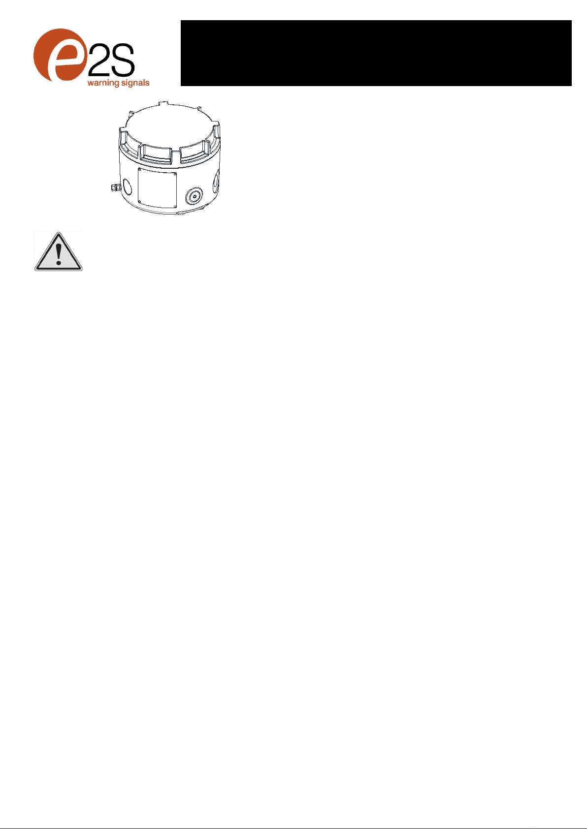
INSTRUCTION MANUAL
D1xJ2 Junction Box
For use in Hazardous Locations
1) Warnings
•DO NOT OPEN WHEN AN EXPLOSIVE
ATMOSPHERE IS PRESENT
•DO NOT OPEN WHEN ENERGISED
•POTENTIAL ELECTROSTATIC CHARGING
HAZARD - CLEAN ONLY WITH A DAMP
CLOTH
•DO NOT PAINT
•TO REDUCE THE RISK OF IGNITION OF
HAZARDOUS ATMOSPHERES, THE FIRST
CONDUIT RUN MUST HAVE A SEALING
FITTING CONNECTED WITHIN 18 INCHES
OF ENCLOSE. SUBSEQUENT CONDUIT
RUNS MUST HAVE A SEALING FITTING
CONNECTED AS CLOSE AS PRACTICAL TO
THE WALL OF THE ENCLOSURE, BUT IN
NO CASE MORE THAN THE SIZE OF THE
CONDUIT OR 50MM, WHICHEVER IS THE
LESSER.
•TO PREVENT IGNITION OF GROUP A, B, C
AND D ATMOSPHERES - SEE
INSTRUCTION FOR CHEMICAL
COMPATIBILITY
Avertissement:
•NE PAS OUVRIR UN PRESENCE
D’ATMOSPHERE EXPLOSIVE
•NE PAS OUVRIR ENERGIE
•DANGER POTENTIEL CHARGE
ÉLECTROSTATIQUE - NETTOYER
UNIQUEMENT AVEC UN CHIFFON HUMIDE
•NE PAS PEINTURER
•POUR RÉDUIRE LE RISQUE
D'INFLAMMATION DES ATMOSPHÈRES
DANGEREUSES, LE PREMIER CONDUIT DE
CONDUIT DOIVENT AVOIR UN RACCORD
D'ÉTANCHÉITÉ RACCORDÉ À MOINS DE 18
POUCES DE L'ENFERMEMENT. POUR
SUBSÉQUENT LES CONDUITES DE
CONDUIT LA DISTANCE ENTRE LA
SURFACE DE LA MASSE DE REMPLISSAGE
AU PLUS PRÈS DE L’ENVELOPPE DOIT
ÊTRE AUSSI PETITE QUE CE QUI EST
RÉALISABLE MAIS EN AUCUN CAS
SUPÉRIEURE À LA PLUS PETITE DES
DIMENSIONS CORRESPONDANT À LA
TAILLE DU CONDUIT OU À 50 MM.
•POUR PRÉVENIR L'INFLAMMATION DES
ATMOSPHÈRES DES GROUPES A, B, C ET
D-VOIR L'INSTRUCTION POUR LA
COMPATIBILITÉ CHIMIQUE
2) Rating & Marking Information
2.1 NEC & CEC Class / Division Ratings for US / Canada
The D1xB2J2 Junction Box complies with the following
standards:
UL 1203 (Ed. 5) 2018
CSA C22.2 No. 30-M1986 (Ed. 3) 2016
CSA C22.2 No. 25 (Ed. 4) 2017
CSA C22.2 No. 205 (Ed. 3) 2017
The D1xJ2 Junction Box is rated as follows:
Class I Div 1 Group ABCD T4A Ta -55°C to +80°C
Class I Div 1 Group ABCD T5 Ta -55°C to +75°C
Class I Div 1 Group ABCD T6 Ta -55°C to +60°C
Class II Div 1 Group EFG T4A Ta -55°C to +80°C
Class III Div 1 Ta -55°C to +80°C
Installation must be carried out in compliance with the
National Electric Code / Canadian Electric Code
2.2 NEC Class / Zone ratings US
The D1xJ2 Junction Box complies with the following
standards:
UL 60079-0 (Ed. 6) 2017
UL 60079-1 (Ed. 7) 2015
UL 60079-31 (Ed. 2) 2015
The D1xB2J2 Junction Box is rated as follows:
Class I Zone 1 AEx db IIC T4 Ta -55°C to +80°C
Class I Zone 1 AEx db IIC T5 Ta -55°C to +70°C
Class I Zone 1 AEx db IIC T6 Ta -55°C to +55°C
Zone 21 AEx tb IIIC T106°C Ta -55°C to +80°C
Installation must be carried out in compliance with the
National Electric Code.
2.3 CEC Class / Zone ratings Canada
The D1xJ2 Junction Box complies with the following
standards:
CAN/CSA C22.2 No. 60079-0 (Ed. 3) 2015
CAN/CSA C22.2 No. 60079-1 (Ed. 3) 2016
CAN/CSA C22.2 No. 60079-31 (Ed. 2) 2015
The D1xB2J2 Junction Box is rated as follows:
Ex db IIC T4 Ta -55°C to +80°C
Ex db IIC T5 Ta -55°C to +70°C
Ex db IIC T6 Ta -55°C to +55°C
Ex tb IIIC T106°C Ta -55°C to +80°C
Installation must be carried out in compliance with the
Canadian Electric Code
2.4 ATEX / IECEx certification
The D1xJ2 Junction Box complies with the following
standards:

_______________________________________________________________________________________________________________________________
European Safety Systems Ltd. Impress House, Mansell Road, Acton, London W3 7QH [email protected] Tel: +44 (0)208 743 8880
www.e2s.com Fax: +44 (0)208 740 4200
Document No. D191-00-501-IS Issue 218-01-2021 Sheet 2 of 5
Flame Path internal thread on
base shown hatched
Flame Path external thread on
lid shown hatched
EN IEC60079-0:2018 / IEC60079-0:2017 (Ed 7)
EN60079-1:2014 / IEC60079-1 (Ed. 7) (2014)
EN60079-31:2014 / IEC60079-31 (Ed. 2) (2013)
The D1xJ2 Junction Box is rated as follows:
Ex db IIC T4 Gb Ta -55°C to +80°C
Ex db IIC T5 Gb Ta -55°C to +70°C
Ex db IIC T6 Gb Ta -55°C to +55°C
Ex tb IIIC T106°C Db Ta -55°C to +80°C
Model No.: D1xJ2
Certificate No. DEMKO 19 ATEX 2009X
IECEx ULD 19.0006X
ATEX Mark, Equipment
Group and Category:
CE Marking
Notified Body No.:
The units can be installed in locations with the following
conditions:
Area Classification Gas:
Zone 1
Explosive gas air mixture likely to occur in
normal operation.
Zone 2
Explosive gas air mixture not likely to occur
in normal operation, and if it does, it will only
exist for a short time.
Gas Groupings:
Group IIA
Propane
Group IIB
Ethylene
Group IIC
Hydrogen and Acetylene
Temperature Classification:
T1
450ºC
T2
300ºC
T3
200ºC
T4
135ºC
T5
100ºC (Up to 70°C ambient)
T6
85ºC (Up to 55°C ambient)
Dust Groupings:
Group IIIA
Combustible Flyings
Group IIIB
Non-conductive Dust
Group IIIC
Conductive Dust
Maximum Surface Temperature for Dust Applications:
106ºC
Equipment Category: 2G / 2D
Equipment Protection Level: Gb, Gc, Db, Dc
Ambient Temperature Range: -55°C to +80°C
The junction box must only be installed by suitably qualified
personnel in accordance with the latest issues of the relevant
standards:
EN60079-14 / IEC60079-14: Explosive atmospheres -
Electrical installations design, selection and erection
EN60079-10-1 / IEC60079-10-1: Explosive atmospheres -
Classification of areas. Explosive gas atmospheres
EN60079-10-2 / IEC60079-10-2: Explosive atmospheres -
Classification of areas. Explosive dust atmospheres
CSA C22.1, Canadian Electrical Code, Part I, Safety
Standard for Electrical Installations, Section 32
NFPA 70, and the National Fire Alarm and signaling Code,
NFPA 72
The installation of the units must also be in accordance with
any local codes that may apply and should only be carried
out by a competent electrical engineer who has the
necessary training.
2.2 Ingress Protection Ratings
The product is rated for ingress Protection as follows:
IP rating per EN60529: IP66
Type rating per UL50E / NEMA250: 4 / 4X / 3R / 13
Suitable for exposure to Acetone , Ammonium Hydroxide ,
Diethyl Ether , Ethyl Acetate , Ethylene Dichloride , Furfural,
n-hexane , Methyl Ethyl Ketone , Methanol , 2-NitroPropane
and Toluene.
To maintain the ingress protection rating, the cable entries
must be fitted with suitably rated, certified cable entry and/or
blanking devices during installation.
2.3 Electrical Ratings
It is important that a suitable power supply is used to run the
equipment. The power supply selected must have the
necessary capacity to provide the input current to all the units.
The input current will vary according to the voltage input level.
3) Special Conditions of Use
The enclosure coating is non-conductive and may generate an
ignition-capable level of electrostatic charges under certain
extreme conditions. The user should ensure that the
equipment is not installed in a location where it may be
subjected to external conditions (such as high pressure steam)
which might cause a buildup of electrostatic charges on non-
conducting surfaces. Additionally, cleaning of the equipment
should be done only with a damp cloth.
Flame Path Positions
Model No. Voltage Range
Max.
Power
Max Current
D1xJ2T01
60Vdc max /
260Vac 50/60Hz
max.
10W
20A
D1xJ2D01
10A
D1xJ2M01
2813
II 2G
II 2D

_______________________________________________________________________________________________________________________________
European Safety Systems Ltd. Impress House, Mansell Road, Acton, London W3 7QH [email protected] Tel: +44 (0)208 743 8880
www.e2s.com Fax: +44 (0)208 740 4200
Document No. D191-00-501-IS Issue 218-01-2021 Sheet 3 of 5
3/4" NPT BOTTOM ENTRY
FOR POLE MOUNTING
M20x1.5 SIDE ENTRY
2 OFF POSITIONS
MARKED #
3/4" NPT SIDE ENTRY
2 OFF POSITIONS
MARKED *
117.5 [4.63]
7.0 [0.28]
45.0°
2 OFF FEET SUPPLIED IN STOWED POSITION
SUITABLE FOR POLE OR BRACKET
MOUNTING BEACON
RETAINED BY 2 OFF M5 SCREWS PER FOOT
166.0 [6.54]
83.0 [3.27]
Ø9 [Ø0.36]
BASE CONFIGURED WITH MOUNTING
FEET SET OUT FOR SURFACE MOUNTING
2 OFF FEET CONFIGURED WITH MOUNTING
FEET SET OUT FOR SURFACE MOUNTING
RETAINED BY 2 OFF M5 SCREWS PER FOOT
4) Installation
There are no restrictions on unit orientation.
4.1 Safe Installation Requirements
To maintain the ingress protection rating and mode of
protection, the cable entries must be fitted with suitably
certified cable entry and/or blanking devices during
installation. If conduit is used for installation, seal conduit
within 18 inches from the enclosure.
If entries are fitted with adaptors they must be suitably certified
for the application. Fitting of blanking elements into adaptors
is not permitted.
Check that the ‘O’ ring seal is in place before replacing the
explosionproof cover.
5) Location and Mounting
The Junction Box should only be fixed to services that can
carry the weight of the unit.
The D1xJ2X Junction box can be mounted using one of three
methods.
1. The Junction Box can be surface mounted by removing,
rotating and reinstalling the stowed mounting lugs. These
are suitable for 6mm diameter fixings.
a. Remove 2 x M5 fasteners per
mounting lug
b. Reverse and rotate lug and
reseat onto enclosure
c. Secure lug using the 2 x M5
Fasteners
2. Alternatively the Junction Box can be conduit mounted
using the ¾”NPT entry on the base of the unit.
3. Additionally, the Junction Box can be mounted using the
ratchet adjustable stainless-steel wall bracket assembly.
This is available as an accessory – part code: SP77-0001.
Dimensions in mm[in.]
Fig. 1 Fixing Location for Junction Box
6) Access to the Enclosure
In order to connect the electrical supply cables to the junction
box, it is necessary to open the explosion proof enclosure.
Loosen the locking grub screw in the junction box cover and
then remove the lid to gain access to the chamber. This can
be achieved by unscrewing the cover, taking extreme care
not to damage the threads when doing so.
Fig. 2 Accessing the Enclosure.
On completion of the installation the flameproof threads should
be inspected to ensure that they are clean and that they have
not been damaged during installation. Ensure the O-ring seal
is in place and undamaged.
When fitting the flameproof cover ensure the thread is
engaged correctly. Fully tighten the cover all the way, ensure
no gap is visible between the cover and base of the enclosure.
7) Selection of Cable, Cable Glands, Blanking
Elements & Adapters
When selecting the cable size, consideration must be given to
the input current that each unit is carrying (see section 2.3).
The cable size selected must have the necessary capacity to
provide the input current to all of the units connected to the
line.
The entries are 2-off M20 x 1.5 thread & 5-off ¾” NPT thread
If a high IP (Ingress Protection) rating is required then a
suitable sealing washer must be fitted under the cable glands
or blanking plugs.
For use in explosive dust atmospheres, a minimum ingress
protection rating of IP6X must be maintained.
For use in explosive gas atmospheres, a minimum ingress
protection rating of IP54 must be maintained.
Junction Box
Cover
Warning – High voltage may be present,
risk of electric shock. DO NOT open when
energised, disconnect power before
opening.
Warning –Hot surfaces. External surfaces
and internal components may be hot after
operation, take care when handling the
equipment.
3/4" NPT
Entry
M20 Entry
3/4" NPT
Conduit
Entry

_______________________________________________________________________________________________________________________________
European Safety Systems Ltd. Impress House, Mansell Road, Acton, London W3 7QH [email protected] Tel: +44 (0)208 743 8880
www.e2s.com Fax: +44 (0)208 740 4200
Document No. D191-00-501-IS Issue 218-01-2021 Sheet 4 of 5
NPT plugs should be greased before insertion.
For high ambient temperatures the cable entry temperature
or the cable branching point temperature may exceed 60ºC
and therefore suitable heat resisting cables and cable glands
must be used, with a rated service temperature of at least the
values stated below:
Max Ambient
temperature
(°C)
45
50
55
60
65
70
75
80
Req. cable
gland rating
(°C)
65
70
75
80
85
90
95
100
8) Cable Connections
The units have 2-off M20 x 1.5 threaded entries and 5-off ¾”
NPT x 14 threaded entries.
Electrical connections are to be made into the terminal blocks
or DIN-rail mounted inside the junction box enclosure. See
section 5 of this manual for access to the enclosure.
Wires having a cross sectional area between 0.5 mm² to
2.5mm² can be connected to each terminal way. If fitting 2-off
wires to one terminal way the sum of the 2-off wires must be a
maximum cross sectional area of 2.5mm². For Terminals strip
wires to 5mm, for DIN rails strip to 8mm. Wires may also be
fitted using ferrules. Terminal screws need to be tightened
down with a tightening torque of 0.4Nm / 3.5lb-in and DIN rails
screws to 0.56 Nm / 5 Lb-in. When connecting wires to any
terminals great care should be taken to dress the wires so that
when the cover is inserted into the chamber the wires do not
exert excess pressure on the terminal blocks. This is
particularly important when using cables with large cross
sectional areas such as 2.5mm².
9) Variants
The D1xJ2 Junction boxes are available pre-fitted with 12-way
terminal (Fig. 3a) or DIN Rail (Fig. 3b) connections. A
D1xJ2M01 custom module variant is also available, please
refer to the website for further info.
Fig. 3a – D2xJ2T01 12-way terminal block variant.
Fig. 3b – D2xJ2D01 12-way DIN Rail variant.
10) Earthing
The unit has an external and an internal earth terminal, (please
see fig 4).
Internal earthing connections should be made to the internal
Earth terminal in the base of the housing using a ring crimped
terminal to secure the earth conductor under the earth clamp.
The earth conductor should be at least equal in size and rating
to the incoming power conductors.
External earthing connections should be made to the M5 earth
stud, using a ring crimp terminal to secure the earth conductor
to the earth stud. The external earth conductor should be at
least 4mm2 in size.
Fig. 4: Internal & External Earth Locations
11) Typical Example of 2-way Beacon Wiring
through Junction Box
Internal Earth
Terminal
External Earth
Stud
Note: D1xJ2D01 shown. DIN Rail Earth
terminals are colour coded Green/Yellow.
INPUT
Beacon 2 Beacon 1
-+ -+
- + - +
Beacon 2 Beacon 1
TO BEACONS
E E
Beacon 1 Beacon 2
INPUT
E E
Beacon 2 Beacon 1
TO BEACONS
Fig 5 Wiring Example

_______________________________________________________________________________________________________________________________
European Safety Systems Ltd. Impress House, Mansell Road, Acton, London W3 7QH [email protected] Tel: +44 (0)208 743 8880
www.e2s.com Fax: +44 (0)208 740 4200
Document No. D191-00-501-IS Issue 218-01-2021 Sheet 5 of 5
12) Maintenance, Overhaul & Repair
Maintenance, repair and overhaul of the equipment should
only be carried out by suitably qualified personnel in
accordance with the current relevant standards:
EN60079-19 / IEC60079-19 Explosive atmospheres -
Equipment repair, overhaul and reclamation
EN 60079-17 / IEC60079-17 Explosive atmospheres -
Electrical installations inspection and maintenance
To avoid a possible ELECTROSTACTIC CHARGE the unit
must only be cleaned with a damp cloth.
Units must not be opened while an explosive atmosphere is
present.
If opening the unit during maintenance operations a clean
environment must be maintained and any dust layer removed
Flameproof joints are not intended to be repaired.
This manual suits for next models
4
Table of contents