EA EA-HV 900 Series User manual

实验室电源供应器系列
Laboratory Power Supply Series
EA-HV 9000
Art. Nr.: 26100103 - 114


© EA Elektro-Automatik, DE-41747 Viersen, Helmholtzstr. 31-33, Tel. 02162-3785-0, Fax. 02162-16230
3
技术规格 / Technical specifications
EA-HV 9000系列的技术规格 / Technical specications Series HV 9000
输入电源 / Mains input 90...264VAC / 50/60Hz
输入电流损耗 / Input current consumption 最大10Aeff (230V)
效率 / Efciency cosϕ ≥0.98
干扰抑制 / Interference suppression EN 50081 第2部分 和EN 50082-2
各端子 / Terminals Sub-D模拟接口 / Analogue interface Sub-D
输入端 / Inputs
目标电压与电流 0...10V / Target values U & I
参考电压 + 10V / Reference voltage
连锁回路 / Interlock loop
输出端 / Outputs
监控电压和电流 0...10V / Monitors U & I
参考电压 + 10V / Reference voltage
高压输出端 / High voltage output 带额外接地插座的高压同轴插座
High voltage coaxial socket with additional grounding socket
电压控制 / VOLTAGE CONTROL
可调范围 / Adjustment range 0...100%
调整精度 / Regulationaccuracy
±10%输入电压时的误差 / Difference at input voltage ≤0.05%
无负载-满载时的误差 / No load - full load - difference ≤0.05%
50%负载电流跳跃时的击穿电压 / 约/ approx. 2%
Voltage breakdown at 50% load current leap
负载改动为50%时的设定时间 /
Setting time at 50% load change: ≤ 2ms
动态内阻 / Dynamic internal resistance
1...10Hz ≤ 0.2% 的/ of RLnom )*
10...100Hz ≤ 1% 的/ of RLnom )*
100...10.000Hz ≤ 10% 的/ of RLnom )*
运行8小时以上的稳定度 / Stabilityover8hrs ≤ 0.01%
温度稳定度 / Temperaturestability ≤ 50ppm/K
纹波 / Ripple ≤ 0.05%
电流控制 / CURRENT CONTROL
调整范围 / Adjustment range 0...100%
调整精度 / Regulationaccuracy
±10%输入电压时的误差 / Difference at input voltage +10% ≤ 0.05%
短路/满载时的误差 / Difference short-circuit/full load ≤ 0.05%
运行8小时以上的稳定度 / Stabilityover8hrs ≤ 0.05%
温度稳定度 / Temperaturestability ≤ 500ppm/K
纹波 / Ripple ≤ 0.05%
显示 / DISPLAY
电压显示精确度/Accuracyofvoltageindication ±0.2%+2位数 / Digits
电流显示精确度/Accuracyofcurrentindication ±1%+2位数 / Digits
模拟接口 / ANALOGUE INTERFACE
输入Uset的精确度/ Accuracy of input Uset < 0.4%
输入Iset 的精确度/ Accuracy of input Iset < 1,3%
输出Umon的精确度 / Accuracy of output Umon < 0.5%
输出Imon的精确度 / Accuracy of output Imon < 1%
IEEE接口 / IEEE Interface
分辨率 / Resolution 12 位/ Bit
错误/Error ±1LSB
尺寸(长 宽 高) / Dimensions (W H D) 19'', 3U, 466mm
(* RLnom = Umax / Imax
型号
Model
输出电压
Output voltage
输出电流
Output current
输出功率
Output power
产品编号
Article number
EA-HV 9000-1K2-2000
EA-HV 9000-2K-2000
EA-HV 9000-4K-500
EA-HV 9000-6K-2000
EA-HV 9000-12K-2000
1200V
2000V
4000V
6000V
12kV
1,67A
1A
500mA
350mA
170mA
2000W
2000W
2000W
2000W
2000W
26100103
26100104
26100114
26100105
26100106

© EA Elektro-Automatik, DE-41747 Viersen, Helmholtzstr. 31-33, Tel. 02162-3785-0, Fax. 02162-16230
4
基本信息 / General
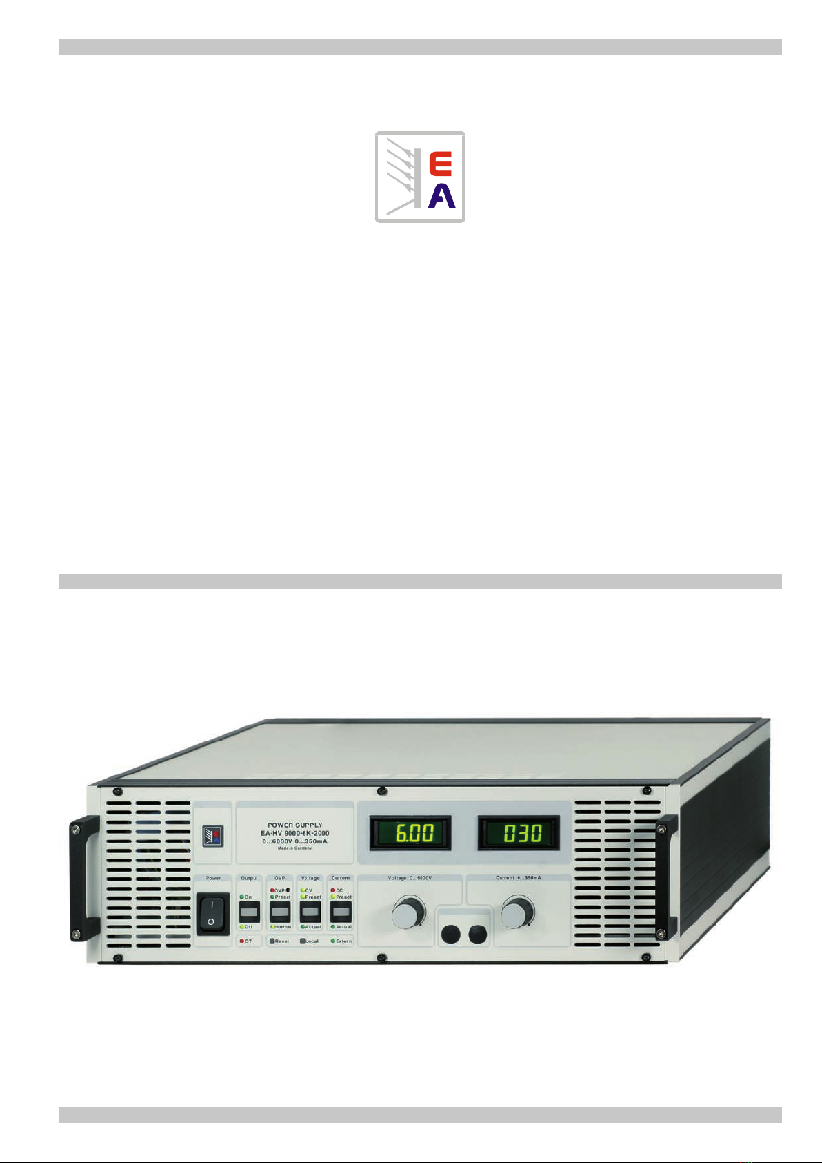
High Voltage Power Supplies Series EA-HV 9000
The power supplies of the series HV9000arefrequency
modulated resonance converters. The push-to-push switch-
ing frequencies are up to 200kHz in the power range of 500
to 2000W. Because the trapezoid shaped voltage is switched
whenpassingzerotheefciencyoftheswitchingstageis
nearly99%.Thismodernconceptinconnectionwithmulti
regulation loops allows the construction of precise high
voltage systems up to 12kV with outstanding regulation
performances. The mains input is 90...264V/50-60Hz with
an active power factor correction.
Function
The units are delivered as desktop versions, but can be modi-
edto19"rackswiththeincludedkit.Voltageandcurrent
are adjusted with 10-turn potentiometers, the values can be
presetinstandbymodeandaredisplayedondigitalmeters.
TheoperationmodesareindicatedbyLEDs.Theoutput
voltageandcurrentcanbeexternallysetbymeansofan
external voltage of 0...10V for 0...rated value (PLC control).
The two external monitor outputs (U & I) each provide an
output voltage of 0...10V for 0...rated value.
InconnectionwiththeIEEE.2interfacepracticallyallsystems
applications are possible. An interlock loop is available on
the programming terminal.
The units of the series HV9000areashover-andcontinu-
ous short-circuit-proof, whereas voltage and current are still
adjustable from 0...100%. On a large fallback of the output
voltage the unit is switched off for a short time and than
automaticallystartingslowly againfrom0Vtothepreset
voltage.Theenergyreachingtheoutputisthereforereduced
to a minimum. So applications with tubes, plasma-gas de-
charging processes and capacitor charging are possible.
The output ripple is less than 5x10⁻⁴ Vpp on max. rated output
current. The ripple depends on the actual output current. On
30% of the rated output current (600 Watts output power)
the ripple is less than 1x10⁻⁴ Vpp.
For special applications a unit with extreme low ripple
<0.01% is available.
高压电源系列 EA-HV 9000
HV9000系列电源实际为调频谐振转换器。在500至2000W
的功率范围内,其推至推式开关频率可高达200kHz。由于
梯形电压过零时会被转换,转换阶段效率将近99%。该先
进理念结合多个调整回路,从而可构建高达100kV的精确高
压系统,并具有突出的调整性能。输入电源为90...264V/50-
60Hz,带主动式功率因素校正。
功能
本机出厂时为桌面式结构,用随附套件可改装成19"机柜
式。通过10圈电位器调节电压和电流,在待机模式下可磔
僊数值,并显示于数字表上。操作模式通过LED灯指示出
来。输出电压和电流也可通过0...10V外部电压对0...额定值
(PLC控制)进行设置。两外部监控输出脚(U & I)对应0...
额定值分别供应0...10V的输出电压。
接上IEEE.2接口,所有系统应用都可实现。编程端子上有
一个联锁线圈。
HV9000系列产品有法蹶和连续短路保护,反之可从
0...100%调节电压和电流。当发现输出电压大量回落时,
产品会短时关闭后再自动开启,电压从0V慢慢上升至预设
值。故到达输出端的能量被减至最小。所以完全可以应用
于电子管、等离子气体的放电加工和电容的充电。
额定输出电流最大时的纹波小于5x10⁻⁴Vpp 。它由实际输出电
流决定。比如:为额定电流的30%时,犴波小于1x10⁻⁴
Vpp
。
针对特殊应用,还可将产品纹波减至<0.01%的超低值。

© EA Elektro-Automatik, DE-41747 Viersen, Helmholtzstr. 31-33, Tel. 02162-3785-0, Fax. 02162-16230
5
描述 / Description
Instruments
The units are equipped with separate illuminated 3½ digit
13mm LCD volt- and amperemeters. In both cases it is
possible to independently switch between the value set,
the actual value or the OVP value.
Remote adjustment of the output voltage
Theoutputvoltagecanbeexternallysetbymeansofan
external voltage of 0...10V for U0 ...Umax. The terminals for
the external programming are on the rear of the unit.
Remote adjustment of the output current
Theoutputcurrentcanbeexternallysetbymeansofan
external voltage of 0...10V for 0...10V for I0...Imax. The termi-
nals for the external programming are on the rear of the unit.
IEEE bus
As an option, the units can be equipped with an IEEE bus
interface or an Ethernet interface. The connection terminals
are located on the rear of the unit. Further details about
measuring and control features of the IEEE or Ethernet
option are available in the option's user instruction manual.
High voltage output
The high voltage output is located on the rear of the unit.
Because of the wide output voltage range there are different
outputcongurationsregardigtheterminationofpolarisa-
tion. These are as follows:
Models 1.2kV to 12kV
The output is equipped with a high voltage connector Y-
seriesfromLEMO.Thepolaritycanbereversedinternally
(only by EA specialists).
Bydefault,the"–“isinternalconnectedtoPE,so"+"iscon-
nected with the center wire of the HV connector. The screen
is connected to PE. The center wire leads the high voltage,
thescreenmaynotbeusedasapartoftheloadwire.
The screen may not be used as load connection. The
return line must be connected to the PE terminal. GND
is always connected to PE.
Part numbers (LEMO):
HV socket ERA 1Y405
HV plug FFA 1Y405
HV lead 106330
仪表
本产品配有分别显示电压和电流的3½数字式、13mm发光
LCD。这两仪表可自主切换显示设定值、实际值或过压保
护值。
输出电压的远程调节
可通过0...10V外部电压对U0 ...Umax输出电压从外部设定。
外部编程端位于产品后板。
输出电流的远程调节
可通过0...10V外部电压对I0 ...Imax输出电流从外部设定。外
部编程端位于产品后板。
IEEE总线
还可选择为本机配上一IEEE总线接口或以太网接口。连接
端位于产品后面。关于IEEE总线或以太网接口选项的测量
和控制特征,可参考用户说明书选项部分。
高压输出端
高压输出端位于产品后板。由于宽范围的输出电压,针对
终端极性不同会有不同的输出配置。具体如下:
1.2kV至12kV型号
此类产品的输出端配有一由LEMO公司制造的Y型高压连
接器。可从内部反接其极性(仅EA公司专业人员方可执
行)。
默认状态下,"–“从内部连到PE,故"+"就连到HV连接器的
中性线。中性线输出高电压,屏蔽线不可用作负载线的一
部分。
屏蔽线不可用做负载连接。回流线必须接到PE端子
上。GND一直连到PE。
元件编号(LEMO):
HV-插座 ERA 1Y405
HV-插头 FFA 1Y405
HV-导线 106330

© EA Elektro-Automatik, DE-41747 Viersen, Helmholtzstr. 31-33, Tel. 02162-3785-0, Fax. 02162-16230
6
描述 / Description
输出端
带HV后缀并配有LEMO连接器的产品型号,随同产品一起
的连接线其屏蔽支线已接地。只有中性线才输出电流。屏
蔽线不可用做负载线。
负载仅可与HV线的中性线(Hi)和负输出端(Lo)相连。如果
负载器要与本机的地相连,必须使用安全的接地器(有PE
标志)。
过压保护 (OVP)
本系列所有产品都有过压保护功能。用电位器从前板可在最
大额定电压的1%到101%范围内设定任何数值。
激活"OVP"开关后预设OVP值显示于电压表上,且"Preset"
LED灯亮。
若因某个原因输出电压高过预设电压(如:操作错误,元件
不良,外部供有电压),换接式振荡器被锁定,不再供应电
量到输出端,且 "OVP"灯亮。要想OVP恢复至正常值,必
须激活“Reset”按钮。
待机操作 (Standby)
可用"Output"按钮关闭输出电压。开关上的LED指示直流输
出状态,但是仅针对手动控制模式。"Off"LED灯亮=输出为
零。"On"LED灯亮=输出被激活。.
注意!LED灯在远程控制模式不指示直流输出
状态!
电压和电流的调节
待机模式下用10圈精密电位器可预设电压和电流值。分别
激活"Voltage"和“Current”推动开关,对应的“ Preset”LED
灯亮,预设值则显示于仪表上。"Actual"灯指示实际值已显
示于仪表上。
Outputs
On units with HV and LEMO-connection sockets the screen
ofthesuppliedconnectioncableisearthed.Onlythecenter
wire leads the output current. The screen must not be
used as load cable.
Theloadmustonlybeconnectedtothecenterwireofthe
HV cable (Hi) and to the negative output (Lo). In case a
load unit should be connected to the earth of the unit use
thesafetygroundconnector(PE-sign).
Overvoltage protection (OVP)
All units are equipped with an overvoltage protection as
standard.Anyvaluebetween1%and101%ofthemax.
rated voltage can be set with the trimmer on the front panel.
The preset OVP value is indicated on the voltmeter after
activating the "OVP" switch and the "Preset" LED lights on.
Iftheoutputvoltagebecomes,foranyreason,higherthan
the preset voltage (e.g. operators fault, defective compo-
nents, external voltage), the switching oscillator is blocked,
andnofurtherenergycomestotheoutput.TheLED"OVP"
lightson.ToresettheOVPtonormal,the“Reset”button
must be activated.
Standby operation
The output voltage can be switched off with the push-button
"Output". The LEDs on the switch indicate the DC output
condition,butonlyduringmanualcontrol.TheLED"Off"
lights on = output zero. The LED "On" lights on = output
active.
Attention! The LEDs do not indicate the DC
output condition in remote control!
Voltage and current adjustment
Thevaluesofthevoltageandcurrentcanbepresetinstandby
modebymeansof10-turnprecisionpotentiometers. The
push switches "Voltage"respectively“Current”mustbe
activated,thecorrespondingLED“Preset”lightsonandthe
preset value is indicated on the meters. The LEDs "Actual"
indicatethattheactualvaluesaredisplayedonthemeters.

© EA Elektro-Automatik, DE-41747 Viersen, Helmholtzstr. 31-33, Tel. 02162-3785-0, Fax. 02162-16230
7
安装
操作产品前,需检查产品外壳、控制件等是否有机械损
坏。
必须使用所供Sub-D插头来连接。
如发现有任何损坏,不可将产品连到市电。打开产品前断
开电源插头。
应由受训工程人员执行本机的服务、维修或校正。
本机仅能在铭板规定电压下操作。如需更换保险丝,有一
点极其重要,即:仅能用与原厂所配保险丝规格和外形尺
寸相同的保险丝来替换。
更换保险丝时应将本机与市电断开。
接地
本机仅可在接地良好的电源插头下操作。因为它通要过电
源线的地线作为产品引线的地。该安全特征不可因无接地
线的扩展线而中断。
制冷
任何时候都必须保持空气流通顺畅,这点非常重要。
注意!
本产品会产生危险电压。故非受训人员不能操作改产
品,也不可打开产品外壳!
过温保护 (OT)
如果产品过热(如:风扇坏,进风孔和排气孔太脏等),产
品将自动关闭,且"OT"灯会亮。产品冷却后又自动打开。
OT LED会指示模拟接口的LOCK信号没有连接。
环境条件
操作过程中,不论是满载操作还是恒定值操作,环境温度
应在0...50°C之间。储存温度可为-40°C和+70°C。相对湿
度不应超过90%,且无凝露。
Installation
Beforetakingtheunitintooperationitisnecessarytoinspect
thehousing,thecontrolsetc.forsignsofphysicaldamage.
The supplied Sub-D plug must be connected.
Ifanydamageisfound,theunitmaynotbeoperatedonthe
mains. Disconnect the mains plug before opening the unit.
Servicing, repairs or calibrations should only be carried
out by trained engineers.
Theunitmustbeoperatedonlyonthevoltagestipulated
onthetypeplate.Ifitisnecessarytochangethefuse,itis
imperativethatitisonlyreplacedbyoneofsamevalueand
physicaldimensionsastheoriginalsuppliedfuse.
The unit must be disconnected from the mains whilst
replacing the fuse.
Grounding
Theunitmayonlybeoperatedusingaproperlywiredand
grounded mains plug as the grounding of the unit leads
viatheearth lineofthepowercable.This safetyfeature
mustnotbedisabledbyusinganextensioncablewithout
a ground lead.
Cooling
It is important that the air circulation remains unimpeded
at all times.
ATTENTION!
The unit generates hazardous voltages. It must not
be operated by untrained personnel and not with
open cover!
Overtemperature protection (OT)
If the unit is overheated (e.g. fan defective, ventilation in-
andoutlets dirty etc.), it willautomaticallyswitchoffand
the LED "OT" will light on. After cooling down the unit will
switchonautomatically.
The OT LED also indicates that the LOCK signal on the
analog interface (rear side of device) is not bridged.
Ambient conditions
During operation, at full load or constant operation, the
ambienttemperaturemayliebetween0...50°C.Thestorage
temperature can be between -40°C and +70°C. The relative
humidityshouldnotexceed90%,non-condensing.
描述 / Description

© EA Elektro-Automatik, DE-41747 Viersen, Helmholtzstr. 31-33, Tel. 02162-3785-0, Fax. 02162-16230
8
描述 / Description
设定电压和电流
输出电压和电流可通过前板的两个电位器进行粗调和细
调。操作模式由两LED灯指示出来:
“CV” = 恒压 (绿灯)
“CC” = 恒流 (红灯)
输出电压(外部电压)的远程设定
远程设定输出电压时,需按表格连接0...10V外部控制电
压。0V外部电压相当于输出端上的0V电压。10V外部电压
则相当于电源的额定输出电压。根据14页引脚分布连接外
部电压。
此时前板上电压调节用电位器失去作用。
输出电流的远程设定
远程设定最大输出电流时,需连接一0...10V外部控制电
压。0V外部电压相当于输出端上的0A电流。10V外部电压
则相当于电源的额定输出电流。根据14页引脚分布连接外
部电压。
此时前板上电流调节用电位器失去作用。
经数字接口的远程控制
本机还可配上一IEEE总线接口或以太网接口。利用该接口可
用电脑控制电压和电流。手动操作与远程控制之间的转换由
发送给机器的第一个指令而自动转换。电源上的"EXTERN"
灯指示为外控状态。
若需转回手动模式,可使用"LOCAL"按钮(仅针对IEEE总
线)。或者用*RST指令,它也可重设接口,并将产品转回
手动控制。
如果数字接口因某个原因没有反应,可关闭产品然后再次
打开。
本型号电源具有下列功能:
测量实际电压/电流
设定电压/电流值
待机(输出开/关)
电流控制激活(CC)
Setting voltage and current
Output voltage and output current are adjustable with two
potentiometers coarse and ne on the front panel. The
operationmodeisindicatedbytwoLEDs:
"CV" = ConstantVoltage(green)
"CC" = ConstantCurrent(red)
Remote setting of the output voltage (ext. voltage)
For remote setting of the output voltage connect a external
control voltage of 0...10V according to the table. An external
voltage of zero volt (0V) is equivalent to 0V on the output,
10V external is equivalent to the nominal output voltage
of the power supply. The external voltage is connected
according to the pin assignment on page 14.
The potentiometer for voltage adjustment on the front panel
is out of function.
Remote setting of the output current
For remote setting of the max. output current connect a
external control voltage of 0...10V. An external voltage of
zero volt (0V)is equivalent to 0A on the output, 10V external
is equivalent to the nominal output current of the power
supply.Theexternalvoltageisconnectedaccordingtothe
pin assignment on page 14.
The potentiometer for current adjustment on the front panel
is out of function.
Remote control via digital interface (optional)
ThedevicecanbeoptionallyequippedwithanIEEEbus
or Ethernet interface. With this interface it is possible to
controlvoltageandcurrentbymeansofacomputer.The
change-over between manual operation and remote control
happensautomaticallywiththerstcommandthatissent
tothedevice.TheLED"EXTERN"onthepowersupplywill
indicate the state of the external control.
Toswitchbacktomanualoperation,pushbutton"LOCAL"
can be used (only with the IEEE bus).Alternatively, the
command *RST will also reset the interface and switch the
device back to manual control.
Incasethedigitalinterfacedoesnotreactanymore,dueto
anyreason,switchtheunitoffandonagain.
Followingfunctionsareavailablewiththispowersupply:
Measure actual values of voltage/current
Set values of current/voltage
Standby(outputon/off)
Current Control Active (CC)

© EA Elektro-Automatik, DE-41747 Viersen, Helmholtzstr. 31-33, Tel. 02162-3785-0, Fax. 02162-16230
9
B模式的指示
如果 "CV"灯亮,本机可当恒压源操作。而"CC"灯则指示产
品可当恒流源操作。这两种操作可自动转换。
过载保护和电流调整
输出端有连续短路保护功能。最大输出电流可从零连续上
调至额定电流值。
功率因素校正 (PFC)
主动式功率因素校正电路在电源输入端能达到大于0.98的功
率因素值。因此无功电流几乎为零,有功电流为正弦形状。
远端编程输出电压和电流
通过模拟接口可从外部控制输出电压和电流,也可监控它们
的实际值。最大额定电压和电流值被标准化成10V,且精确
度<0.2%。各个输出端都有监控信号。
引脚 7 = IMON
引脚 8 = UMON
监控线尾部应焊接一电阻(如:100k)和电容(
如:470nF)进行终止。监控输出端有短路保护,允许最
大负载为1mA。连接线应屏蔽。屏蔽线必须连到引脚10
(GND)。
15针Sub-D插头外壳接到PE,但不可连到监控线的屏蔽线
上。
电压和电流值都可通过高阻抗控制输入脚设定。
所供15针Sub-D插头的3和4脚(电压)与5和6(电流)脚需
空着。+参考2脚要连到电位器的一边,0V参考1脚则连到它
的另外一边。电位器的滑动件需分别连到UPS 3脚(电压)
和IPS 5脚。2脚和4脚不连。
远程开/关
本机可通过控制输入脚SB(9脚)转至待机模式(输出电
压被关断)。利用继电器接点或三极管的开集将9脚连到
+5V 12脚即可实现。断开该连接后,输出被再次打开,并
上升至预设值。
Mode indication
If the LED "CV" is lit, the unit operates as a constant volt-
age source, while the LED "CC" indicates that the unit is
operating as a constant current source. The change-over
happensautomatically.
Overload protection and current regulation
The output is protected against a continuous short-circuit.
The max. output current is continuously adjustable from
zero up to the rated current.
Power factor correction (PFC)
The active power factor correction circuit achieves a power
factor on the mains input of better than 0.98. So the reac-
tivecurrentbecomesnearlytozeroandtheactivecurrent
is sine wave shaped.
Remote programming of output voltage and current
Itispossibletocontroloutputvoltageandcurrentexternally
via the analogue interface as well to monitor the actual
valuesexternally.Themaximumratedvoltageandcurrent
valuesarestandardizedto10Vwithanaccuracyof<0.2%.
The monitor signals are available on the respective outputs.
Pin 7 = IMON
Pin 8 = UMON
Theendofthe monitorcableshouldbeterminatedby a
resistor (e.g. 100k Ohm) and a capacitor (e.g. 470nF). The
monitor outputs are short-circuit protected and the max.
load is 1mA. The cable should be screened. The screen
must be connected to Pin 10 (GND).
The housing of the 15-pole Sub-D plug is connected to PE
and may not be connected to the screen of the monitor
cable.
The voltage and current values can both be set via the high
impedance controle inputs.
The connections on the supplied 15-pole plug on Pin 3
and 4 (Voltage) and Pin 5 and 6 (current) must be opened.
The + reference Pin 2 is to be connected to one side of a
potentiometer and the 0V reference Pin 1 to the other side
of the potentiometer. The slider of the potentiometer must
be connected to UPS Pin 3 (Voltage) resp. to IPS Pin 5
(Current). Pin 2 and Pin 4 are not connected.
Remote on/off
Through the control input SB (Pin 9) the unit can be switched
intostandbymode(outputvoltageoff).Thisiseffectedby
connectingPin9to+5VPin12througharelaycontactor
a transistor with open collector. After opening this connec-
tion the output is switched on again and rises up to the
preset value.
描述 / Description

© EA Elektro-Automatik, DE-41747 Viersen, Helmholtzstr. 31-33, Tel. 02162-3785-0, Fax. 02162-16230
10
操作控制件 / Operating controls
前板
1. 电源开关
2. 输出开/关(待机)切换开关
位于On时= 打开输出电压
位于Off时= 关闭输出电压
3. 复位开关
用于恢复至OVP值。.
4. Preset/Normal OVP切换开关
开关位于"Preset"时,可用螺丝刀转动电位器 OVP (No. 5)
设定所需OVP极限值。设定完成后需调回正常操作模式!
5. OVP极限设定用电位器
该电位器用于设置OVP极限电压。
6. Local-本机开关
该开关可将IEEE总线模式调回标准模式。
7. Preset/Actual电压切换开关
开关位于"Preset"时,电压表13指示预设电压,用电位器9
可调节。位于“Actual”时,指示实际电压。
8. Preset/Actual电流切换开关
开关位于"Preset"时,电流表14指示最大预设输出电流,
用电位器12可调节。位于“Actual”时,指示实际电流。
9. 电压调节用电位器
该电位器用于调节输出电压。
10. 电流调节用电位器
该电位器用于调节最大输出电流。
11. 电压表
电压表显示预设电压、实际电压和OVP电压。
12. 电流表
电流表显示预设和实际输出电流。
Front panel
1. Mains switch
2. Switch output on/off (standby)
Position on = output voltage on
Position off = output voltage off
3. Reset switch
Serves to reset the OVP.
4. Switch Preset/Normal OVP
Inposition"Preset"thedesiredOVPthresholdcanbeset
bymeansofascrewdriverwiththetrimmerOVP(No.5)
Switch back to normal operation after setting it!
5. Trimmer for setting OVP threshold
This trimmer sets the OVP threshold voltage.
6. Local
This switch is used to switch from IEEE bus mode back to
standard mode.
7. Switch Preset/Actual Voltage
In position Preset the voltmeter 13 indicates the preset
voltage, adjusted with potentiometer 9. In position Actual
the actual voltage is indicated.
8. Switch Preset/Actual current
In position Preset the amperemeter 14 indicates the preset
max. output current, adjusted with potentiometer 12. In
positionActualtheactualcurrentisdisplayed.
9. Potentiometer Voltage
Potentiometer for the output voltage adjustment.
10. Potentiometer Current
Potentiometer for the max. output current.
11. Voltmeter
The voltmeter displays the preset, actual and the OVP
voltages.
12. Ammeter
Theammeterdisplaysthepresetandtheactualvalueof
the output current.

© EA Elektro-Automatik, DE-41747 Viersen, Helmholtzstr. 31-33, Tel. 02162-3785-0, Fax. 02162-16230
11
前视图 / Front view
1 2 3 4 65 87 9 10
11 12
1 电源开关 / Mains switch
2 输出:开/关(待机)/Output:on/off(standby)
3 复位开关(重置 IEEE总线) / Reset (resets the IEEE bus)
4 Preset/Normal (调节 OVP值)切换开关 / Preset/Normal (adjustment OVP)
5 OVP极限调节用电位器 / Adjusting the OVP threshold
6 Local切换开关 (调回正常模式)(onlyIEEE)/Switchbacktonormalmode(onlyIEEE)
7 Preset/Actual 电压切换开关 / Voltage
8 Preset/Actual 电流切换开关 / Current
9 电压调节用电位器 / Voltage adjustment
10 电流调节用电位器 / Current adjustment
11 电压表 / Voltmeter
12 电流表 / Amperemeter

© EA Elektro-Automatik, DE-41747 Viersen, Helmholtzstr. 31-33, Tel. 02162-3785-0, Fax. 02162-16230
12
后视图 / Rear view
IEEE BUS
RS 232 - 9pol.
Analogue Interface
15 pol.
Mains
Output terminals
LOHI

© EA Elektro-Automatik, DE-41747 Viersen, Helmholtzstr. 31-33, Tel. 02162-3785-0, Fax. 02162-16230
13
模拟接口
模拟接口各引脚连接 (Sub-D, 15针)
1 0V-参考
2 + 参考 (0...10V)
3 UPS (预设输入电压电位器 0...10V)
4 UPOT (预设输出电压电位器 0...10V)
5 IPS (预设输入电流电位器 0...10V)
6 IPOT (预设输出电流电位器 0...10V)
7 IMON (实际输出电流 0...10V)
8 UMON (实际输出电压 开 0...10V)
9 SB (待机) 控制输入: +5V = 待机, offen = 打开
10 GND (GND/外部编程用0V)
11 LOCK (安全回路/当HV负载用时失效)
12 +5V 输出(待机模式下连到9脚)
13 不连接
14 +15V 输出
15 不连接
正常操作的基本设定
正常操作时,模拟接口需进行下列连接:
3脚- 4脚,
5脚- 6脚,
10脚- 11脚
随附产品的Sub-D插头已做了上述连接。
后板输出端
HI (HV插座) 按照极性不同(标准为+),连接中心触点的+ 或–输出脚。屏蔽线连到安全地PE,但
决不可连到负载上。
LO (黑色) –输出脚
(黄色) PE安全地,负载的回路
接口 (按照设置)
24针插座 IEEE-Bus接口 (如有配)
9针Sub-D连接器 RS-232接口 (如有配)
15针Sub-D连接器 模拟接口 (需一直插上)
RJ45连接器 Ethernet-以太网端口 (如有配)

© EA Elektro-Automatik, DE-41747 Viersen, Helmholtzstr. 31-33, Tel. 02162-3785-0, Fax. 02162-16230
14
Analogue interface
Pin connection on the analogue interface, Sub-D 15 pole
1 0V-Reference
2 + Reference (0...10V)
3 UPS (Input preset voltage potentiometer 0...10V
4 UPOT (output preset voltage potentiometer 0...10V
5 IPS (Input pre set current potentiometer 0...10V)
6 IPOT (output pre set current potentiometer 0...10V)
7 IMON (output actual value current 0...10V)
8 UMON (output actual value voltage 0...10V)
9 SB(Standby)controlinput:+5V=OFF(standby),open=ON
10 GND (GND/0V for external programming)
11 LOCK(safetyloop/inhibitforHVload)
12 +5Voutput(forstandbymodeconnecttopin9)
13 N.C.
14 +15V output
15 N.C.
Fundamental settings for normal operation
For normal operation the following connections must be carried out on the analogue interface:
Pin 3 - Pin 4,
Pin 5 - Pin 6,
Pin 10 - Pin 11
TheseconnectionsarealreadymadeattheincludedSub-Dplug.
Output terminals on the rear side
HI(HVsocket) +or–outputonthecentralcontact,dependingon
polarity(standardis+).Thescreenisconnectedtothe
safetygroundPEandmayneverbeconnectedtotheload.
LO (black) –output
(yellow) PEsafetyearth,returnpathfortheload
Interfaces (according to setup)
24-pole socket IEEE bus interface (if equipped)
9-pole Sub-D connector RS-232 interface (if equipped)
15-poleSub-Dconnector Analogueinterface(mustalwaysbeplugged)
RJ45 connector Ethernet port (if equipped)

© EA Elektro-Automatik, DE-41747 Viersen, Helmholtzstr. 31-33, Tel. 02162-3785-0, Fax. 02162-16230
15
提示 / Hints
提示
- 电源插头必须插进无障碍电源插座上。
- 输出端的极性可通过PCB"UMPOLER"从内部反接。
该操作仅可由受训人员来执行。
- 300V以上型号的0V-HV输出端与安全接地器PE从内部
相连。若输出端已反接,则+输出端要接到安全接地器
PE。
- 用螺丝刀可从前板调节过压保护值(OVP)。按下"Preset"
按钮该数值可显示于电压表上。若OVP被激活,可激
活"Reset"按钮使本产品恢复至正常模式。
- 随附插头必须一直插到模拟接口插座上。见14页。
Hints and tips
- The mains plug must be connected into a free acces-
sible mains socket.
- Thepolarityoftheoutputcanbeinternallyreversedby
meansofthePCB"UMPOLER".
Thismayonlybecarriedoutbytrainedpersonnel.
- Onunitsabove300Vthe0V-HVoutputisinternally
connectedwiththesafetygroundconnectorPE.
In case the output has been reversed, than the +
outputisconnectedtothesafetyground
connector PE.
- The overvoltage protection (OVP) can be adjusted on
thefrontpanelbymeansofascrewdriver.Thevalue
can be indicated on the voltmeter after pressing the
"Preset"button.IncasetheOVPisactivated,theunit
canberesettonormaloperationbyactivatingthe"Re-
set"button.
- The included plug must always be plugged in to the
analogue interface socket. See page 14.


EA-Elektro-Automatik GmbH & Co. KG
研发 - 生产 - 销售一体化
Development - Production - Sales
Helmholtzstraße 31-33
41747 Viersen
Germany
Tel: +49 2162 / 37 85-0
Fax: +49 2162 / 16 230
www.elektroautomatik.cn
This manual suits for next models
5
Table of contents
Other EA Power Supply manuals
Popular Power Supply manuals by other brands

Thermal Dynamics
Thermal Dynamics Pak Master 75XL Plus Service manual

Xigmatek
Xigmatek VECTOR manual

Conductix-Wampfler
Conductix-Wampfler 91008-111-3130923 operating instructions

VOLTCRAFT
VOLTCRAFT SPS-1000I operating instructions

Altronix
Altronix AL600UL3 quick start guide

Cosel
Cosel LMA Series instruction manual