Eagle 1403 User manual

Rev. 4.0 2/97
MODEL 1403 REMOTE CONTROL RELAY MODULE
INSTALLATION MANUAL
1.0 GENERAL.
The Model 1403 REMOTE CONTROL RELAY MODULE provides four SPDT relays which can be controlled from
the central station. Two Model 1403's can be daisy-chained to provide eight (8) relay control outputs. Relays can
be configured for momentary or latching operation; momentary delay can be programmed long or short. There is a
master set and reset command.
2.0 REQUIREMENTS.
2.1 POWER.
Operating Voltage: 9 to 14 VDC.
Current Draw (standby): 20 mA.
Current Draw (all set): 170 mA.
2.2 SYSTEM
The Eagle Model 1403 requires the following hardware:
1) Eagle Two Way Audio Verification Module (1403 ready)
--- or ---
2) Eagle Remote Arm/Disarm Module (Models 1404 or 1407)
3.0 CONNECTIONS.
3.1 REQUIRED CONNECTIONS.
INTERCONNECT CABLE. Connect one end of the two conductor wire included with the Model 1403 to the “IN”
connector on the Model 1403. Connect the other end of the cable to the “1403” connector on the 1250 or P7 on
the Model 1241 or to P1 on the Model 1404. See appropriate manual to connecting Eagle modules for further
instructions.
POWER CONNECTIONS. The Model 1403 requires +12VDC and GROUND connections. These connections
may be made to any +12VDC supply available including the Model 1241 or Model 1404 terminal strips.
3.2 OPTIONAL CONNECTIONS.
MULTIPLE MODEL 1403's. If it is desired to use more than one (1) Model 1403, an additional Model 1403 may be
interconnected via the two conductor cable in a daisy chain configuration. Connector P2 is the output on Model
1403 for additional modules. Connect P2 of the first module to P1 of the second module. BE SURE TO
CONFIGURE EACH MODULE TO DIFFERENT NUMBER BANKS (1 through 4 or 5 through 8) FOR REMOTE
CONTROL (See paragraph 4.1.)

2
TERMINAL 1
TERMINAL 2
P7
P1
+12
GND
RY1
NO
RY1
NC
RY1
COM
RY2
NO
RY2
NC
RY2
COM
RY3
NO
RY3
COM
RY3
NC
RY4
NO
RY4
COM
RY4
NC
EAGLE SECURITY PRODUCTS
MODEL
NOT NOT
USED USED
12345678
12345678
P2
24VAC
ON
OFF
123456
SW1
1241 1403
MODEL
THERMOSTAT
POWER
WARM UP
THERMOSTAT
NORMAL
THERMOSTAT
( SET TO 50 )
( SET TO 72 )
TYPICAL APPLICATION
RAISES TEMPERATURE OF
A BUILDING WITH A
SIMPLE PHONE CALL. ADDITIONAL
MODEL 1403
4.0 CONFIGURATION.
4.1 MODEL 1403 DIP SWITCHES.
The dip switches on the Model 1403 may be configured to best suit the application. The adjustable
parameters include momentary or latching; momentary duration; activation digits used.
SWITCHES 1 - 4: control whether the relay is momentary or latching.
SW1 - OFF = RELAY 1 LATCHING
ON = RELAY 1 MOMENTARY
SW2 - OFF = RELAY 2 LATCHING
ON = RELAY 2 MOMENTARY
SW3 - OFF = RELAY 3 LATCHING
ON = RELAY 3 MOMENTARY
SW4 - OFF = RELAY 4 LATCHING
ON = RELAY 4 MOMENTARY
SWITCH 5: Controls relay bank; high or low.
SW5 - OFF = RELAYS 1-2-3-4 (low bank)
ON = RELAYS 5-6-7-8 (high bank)
Switch 5 controls which four digits control the module. If switch 5 is OFF then commands 1
through 4 control the module. If switch 5 is ON then commands 5 through 8 control the module. If two
modules are used, it is desirable to have one module on each setting thus giving eight (8) independent
'zones'. If both modules are set to the same range, then two relays will be activated with each command.
SWITCH 6: Controls momentary duration, if selected.
SW6 - OFF = MOMENTARY ACTIVATION DURATION = 350 mSEC
ON = MOMENTARY ACTIVATION DURATION = 1.5 SEC

3
5.0 OPERATION.
5.1 RELAY ACTIVATION / DE-ACTIVATION.
Once the communication link has been established via a Two Way Voice Module or a Remote Arm/disarm Module,
the Model 1403 REMOTE CONTROL RELAY MODULE can be accessed and commanded via a Touch-Tone
command. Each command consists of two digits. The first digit is the #. This is followed by a single number
ranging from 1to 8. Dip switch 5 sets which group of four numbers command the module. All valid and
accepted commands are responded to with an acknowledgment 'beep'.
Example. If you have configured the module for a low bank (digits 1through 4) and you wish to activate relay
three press #then 3on the phone touch pad. If the command sent was a valid command and the module
accepted the command, it will generate an acknowledgment 'beep'.
5.2 ACKNOWLEDGMENT BEEPS.
The Model 1403 generates two different acknowledgment beeps. The tone generated is dependent on the
command sent and the state of the relay being commanded. If the relay is a momentary relay, then any valid
activation will generate a 'beep bop'. If the relay is a latching relay then the state of the relay will determine the
type of beep sent. If the relay is not currently set and a command is sent to set the relay, then the module will
generate a 'bop, bop/beep'. If the relay is currently set and a command is sent to reset the relay, then the module
will generate a 'beep bop' as an acknowledgment. Master set and master reset tones follow the latching tones.
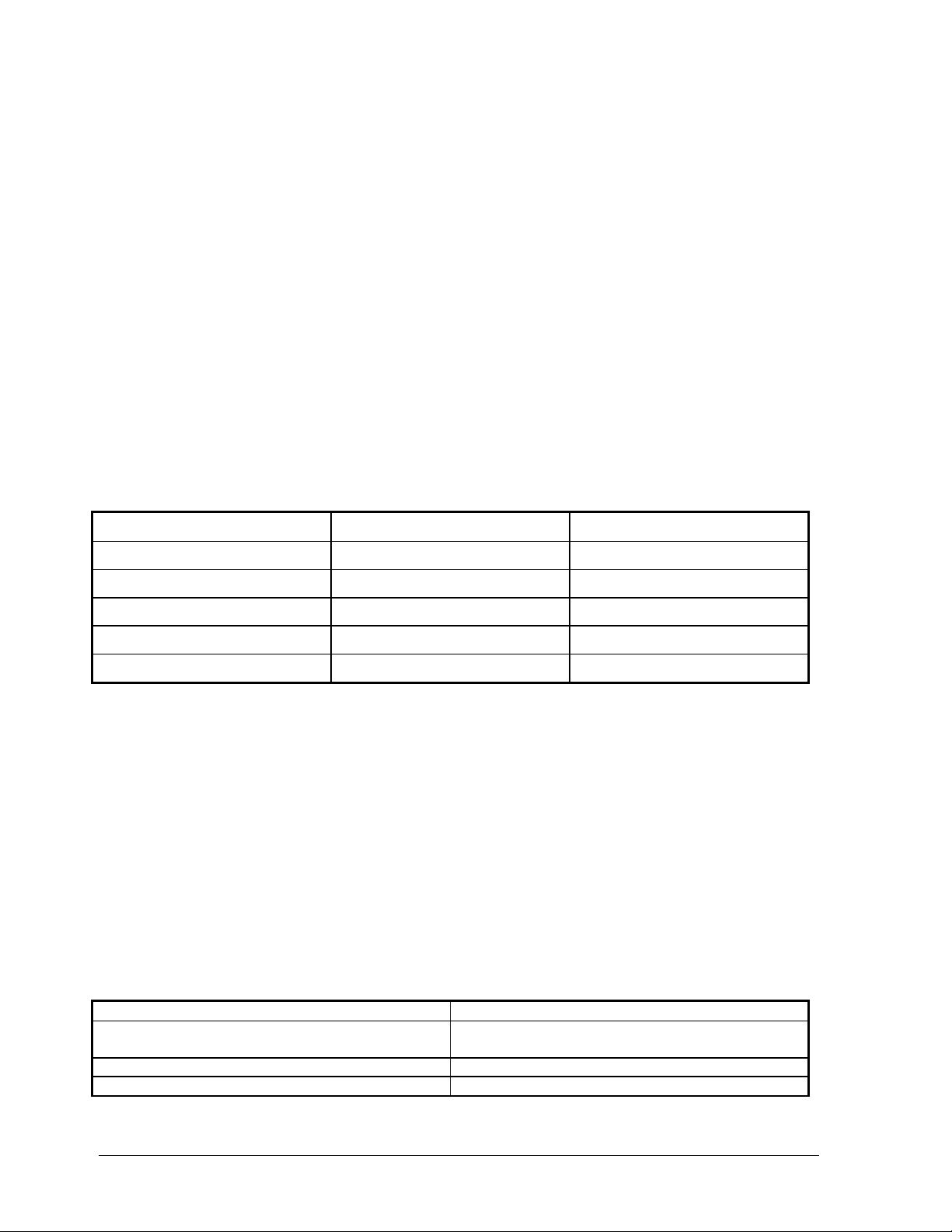
The following chart summarizes the acknowledgment beeps.
RELAY TYPE / COMMAND CURRENT STATUS TYPE OF BEEP
LATCHING SET BEEP / BOP
LATCHING RESET BOP, BOP / BEEP
MOMENTARY N / A BEEP / BOP
MASTER SET N / A BEEP / BOP
MASTER RESET N / A BOP, BOP / BEEP
5.3 MASTER SET / RESET COMMANDS.
The Model 1403 has two commands which are master set and reset commands. The master set command will set
or activate ALL relays. This includes momentary and latching relays. A momentary relay will energize for the
duration to which it is programmed (see switch 6). Latching relays will latch into their energized state. Any relays
which are already in their energized state when the master set command sent will not be effected.
The master reset command will de-activate or de-energize ALL latching relays. That is, all relays which are
energized will be de-energized after the master reset command. The master reset command does not effect relays
which are programmed momentary.
Both the master set and reset commands are two digit commands. The master set command is a #followed by
an *. The master reset command is a #followed by another #.
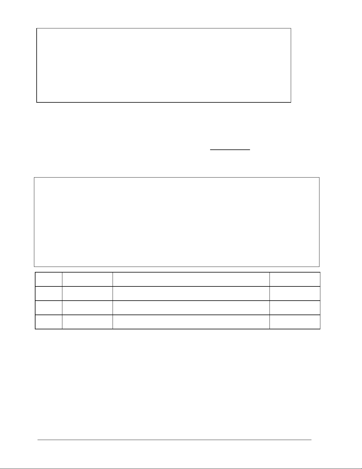
COMMAND SUMMARY
COMMAND FUNCTION
#'number' Commands relay identified by 'number' to
set or reset
# # Master RESET
# * Master SET
Features and specifications subject to change without notification.

4
LIMITED WARRANTY
Eagle Security Products, Inc. warrants that the products of its manufacture shall be free from defects in materials or workmanship to one
year from the date of invoice if such goods have been properly installed, are subject to normal proper use, and have not been modified in
any manner whatsoever. Upon return of the defective product to the nearest Eagle Security Products dealer, Eagle Security Products will,
at its sole discretion, either repair or replace, at no cost to the customer, such goods as may be of defective material or workmanship.
Customers outside the United States are to return products to their distributor for repair.
EAGLE SECURITY PRODUCTS, INC. SHALL NOT UNDER ANY CIRCUMSTANCES BE LIABLE FOR ANY INCIDENTAL OR
CONSEQUENTIAL DAMAGES ARISING FROM LOSS OF PROPERTY OR OTHER DAMAGE OR LOSSES OWING TO THE FAILURE
OF EAGLE SECURITY PRODUCTS' PRODUCTS BEYOND THE COST OF REPAIR OR REPLACEMENT OF ANY DEFECTIVE
PRODUCTS.
EAGLE SECURITY PRODUCTS INC. MAKES NO WARRANTY OF FITNESS OR MERCHANTABILITY AND NO OTHER WARRANTY,
ORAL OR WRITTEN, EXPRESS OR IMPLIED, BEYOND THE ONE YEAR WARRANTY EXPRESSLY SPECIFIED HEREIN.
RETURNS:
IMPORTANT: COPY, COMPLETE AND RETURN THIS FORM WITH YOUR RETURNS.
NOTE: YOU MUST OBTAIN A RMA NUMBER FROM TECH SUPPORT FROM THE FIELD BEFORE RETURNING
PRODUCT.
SECTION 1 (TO BE COMPLETED BY DEALER) DATE ............/............/............
RMA NUMBER ...........................................................................
DEALER NAME ............................................................................ PHONE NO. (........) ..........................
ADDRESS ............................................................................ FAX NO. (........) ..........................
CITY/STATE ................................................ ZIP ..................... CONTACT .....................................
SHIP TO............................................................................ SHIP REPAIRED PRODUCT VIA:
............................................................................ UPS UPS BLUE UPS RED
Y
OUR FED-EX # ..............................
SECTION 2 (TO BE COMPLETED BY DEALER)
LINE #
PART NUMBER
DESCRIBE PROBLEM
COSMETIC
REPAIR (Y/N)
1
2
3
Eagle Security Products, Inc.
11650 Genesee Street Suite #2
Alden, NY 14004-9630
web site: www.isg.net/eagle/
SALES: 800.447.E3 A2 G4 L5 E or 716.937.0095
FAX: 716.937.3127
TECHNICAL SUPPORT HOTLINE:
800.447.E3 A2 G4 L5 E
Table of contents
Other Eagle Control Unit manuals