EAGO AM219 User manual

AM219/220/221 Installation Introduction

01 Contenets
02 Safety Instruction
03-08 Component Struction and Water and Wire Instruction Diagram
05 Faucet Pipe Connecting Diagram
05-06 Installation Steps
06 Parameter
07 Control System Connecting Diagram
08 Water Testing
09 Faucet Instruction
09-10 Installation Steps and Parameter
11 Control System Connecting Diagram
12 Water Testing
13 Faucet Instruction
14-17 Control Panel Instruction
18 Notice
19 Troubleshooting
20 Maintenance Card
01
1. Safety information
Hazard symbol: this icon reminds users that product is accompanied by dangerous voltage!
Warning symbol: this icon reminds users that the product is accompanied by important operating and maintenance
instructions!
【Warming】
1. To prevent fire or electric shock, please do not expose the controller to rain or wet environment. Please do not open the
controller cover as some dangerous high voltage parts are inside the controller. Only the qualified service personnel
can be entrusted to repair the controller.
2. Any changes or modifications of the controller without expressly approved by the controller manufacturer or its authorized
are possible cause some inconvenience to the user during the usage.。
【Note】
1. Please read this manual carefully so that you know how to use this controller properly.
2. Please keep this manual after the installation. Please contact your local dealer or our service center when the controller
need to be repaired.
【Terms and Conditions】
1. Please unplug the controller plug when the controller does not use in a long time.
2. Please confirm all wires are connected correctly before turn on the power.
3. Please install the controller in dry and ventilated environment. Do not closed to heat sources, away from direct
sunlight, mechanical vibration, moisture, and dust environment. Also avoid to near heat radiation objects.
【Helpful Hints】
1. To extend the service life of the controller, continuous switching time interval must be at least 30 seconds.
2. Please turn off the power after usage.
3. Make sure the power is consistent with voltage rating of the controller. Otherwise the controller can not be used, or even
burn the controller.
4. To double-check whether the load specifications is consistent with the controller requirement .Otherwise the controller can
not be used, or even burn the controller.
5. Please turn on the controller again when the controller is crashed,
Installation Instruction 02

AC
D
E
B
F
AM219
03
AM219 Water and Wire Instruction Diagram
625
560
720
600
100
350
1580
1580
660
660
550
350
Component Struction
Power install position
Hot/Cold water inlet
install position
Skirt panel
Bathtub feet
Am219 Stainless steel
bracket
Electronic control box
Fixed clip
Suction (stainless steel)
(H-04)
½ nozzle with high
round adjustment switch
Control panel
WTC200 Water pump
(220V/50HZ)
Skirt panel glass
Chromatic light
Chromatic light
Skirt cover
New bottom jet
New side jet
1.5KW Heater
Hot/Cold water faucet
Waterproof hand
shower holder
3629-A-5 Plastic
drain
Control panel
Installation Instruction 04


Faucet Pipe Connecting Diagram
Waterfall inlet
09
AC220V/50Hz AC220V/50Hz
AC110/60HZ-240V/50Hz
AM219
AM221
1200W 1500W 15W
1501 Hand shower
Selector switch
Hot water switch Cold water switch
Cold water
Hot water
Installation step
The product use standard accessories. Please refer to production tech parameter and follow the below steps for installation:
1. Confirm the direction for the product.→2.Adjust the product for horizontal.→3. Connect the water-in and water drain.→4.Connect the power.→
5.Check and confirm.→6.Repositon.→7.Pour water and test.
1. Confirm the direction for the product
Please see to the product technique diagram and related tech parameter to connect the water drain pipe, power socket, water inlet pipe. Confirm if
there is enough space for the connection.
2.Adjust the product for horizontal
Adjust the adjustable leg of the product, turn it into horizontal level.
3. Connect the water-in and water drain
Standard figuration
Installation step
The water outlet pipe lays in the bottom of the bathtub, with diameter 38mm, the pipe could be elbow in whatever way you like. Please put the pipe into
water drain system and seal it well. Please keep the pipe running through to avoid water exhausted.
4. The power connection
This item is adjustable by the required power; Please refer to the technique parameter for the direction of the power socket. Pay attention to the water-
proof; connect the connector plugs into the socket. (Noted: the yellow-green bi-color wire from the water pump is the ground line, the diameter is 8mm.)
5. Check and confirm
After the above steps, please check the connection points are sealed or not. Clean the dirty things in the bathtub and open the water drain. Wash the
bathtub by water. In order not to stuff the water drain and jets, please do clean the dirty things before washing.
6. Reposition
Reposition the product to where you want.
7. Pour the water in, check and test before use
Confirm the bathtub is clean. Close the water drain and start storing water. When then water level is higher than the probe, turn on the bathtub and
test the functions according to the control panel instruction.
Electric parameter
Model
No. Parameter
Spare part
Rate voltage
Rate power
Rate voltage
Rate power
Water pump Ozone Bottom
light Heater Speaker
Installation Instruction 10

The product adopts the standard accessories. Please refer to the product tech parameter and follow the installation steps as below:
Confirm the product install position connect the drain connect the water inlet pipe check and clean water testing
1. Confirm the product install position
Please refer to the product tech parameter to connect the water inlet pipe, power socket and drain tube, and check if there is enough space
for the connection.
2.Connect the drain
The drain pipe is lay in the bottom of the bathtub, with diameter 38mm. The pipe could be elbowed and extended easily. Please put the pipe
into the drain system and seal it well. Please keep the pipe running through to avoid water exhausted.
3. Connect the water inlet pipe
The inlet pipe is withstand voltage netted pipe. Please connect the cold and hot water joints as shows on the connection. Do not reverse them.
In order to facilitate the future use and maintenance, please install a valve on each end of cold and hot water pipes.
4. Check and clean
Please check the connections are sealed well or not after the installation. Clean the dirt in the bathtub and open the drain to clean the bathtub.
5. Water testing
Close the drain after the bathtub is clean. Start storing water and the bathtub can be used when it isn’t leakage.
Control panel
11
Control System Connecting Diagram Water testing
Installation Instruction 12
WIRING DIAGRAM OF MASSAGE BATH CONTROLLER
Input Vollage: AC220-240V 50/60Hz
Max.total load : 15.8A
Waterproof : IPX5
Model: 16B40
Radio antenna
Cont ro l panel
Water level sensor
Temperature sensor
Water flow switch
of heater
Speaker 8Ω 15w
Light
DC12V/1W
Ozone
DC12V/8W
NL
AC power Input
Heater
AC230/Max.1.5KW
Pump
AC230V/MAX.2HP
Blower
AC230V/Max.400W
X
W
T
K
S
L
♪
1Power on/off button
2
3
Left/Decreas key
1 2 3 4
4Function selection key of rotary style
5678 9
5
6
7
8
9
Radio/Audio icons and operation status
Ozone icons and operation status
Light icons and operation status
Surfing water pump icon and operation status
Thermostatic icon and operation status
Right/Increas key

Three-piece faucet instruction and adjustment: installation way: left side is cold water, right side is hot water.
o
A. The valve is use to adjust the outlet water. The water will come out from the hand shower when it is turn left 90 ; and water
o
comes out from waterfall when it is turn to right90 ;
B. Red symbol on water inlet pipe is hot water. The H symbol is under the left & right side of the faucet handle. To turn it on by
counterclockwise. The water temperature can be adjusted by the valve. More and more cold water would be added into the
bathtub and the water temperature would be colder and colder when it is more to the right. To turn it off by clockwise. The
rotation angle is 90 °;
C. Blue symbol on water inlet pipe is cold water. The C symbol is under the left & right side of the faucet handle. To turn it on by
counterclockwise. The water temperature can be adjusted by the valve. More and more hot water would be added into the
bathtub and the water temperature would be higher and higher when it is more to the right. To turn it off by clockwise. The
rotation angle is 90 °;
D. The water is going in from the waterfall, also the water can going in from the hand shower. Usually the water going in from
the hand shower is used to clean the physical and head.
13
1. Feature Overview
Model
No.
Function
No.
Child lock function
7
6
8
9
10
11
12
13
PB3133-2012
1) Water pump surfing: AC220V/1200W 2) Bottom light : DC12V/2W
3) Heater : AC220V/1500W 4) zoneO :DC12V/6W
5) Speaker : 8Ω/15W
Hand shower Waterfall Off On Off On
Off
Usage instruction
√
1
Water pump surfing
2√
FM Radio
Bubble
3√
√
√
√
√
√
√
√
X
X
X
4
5
Heating/Thermostat
Temperature probe
Bottom light
Bluetooth
Mp3
Water level probe
Ozone
Self cleaning
Timing(60 minutes)
Note: “√" means function include; “X”means function exclude.
Device controlled by the control system
Faucet Instruction Control System Connecting Diagram
Installation Instruction 14

7.2 Touch “ 、 ” continuously when the system is on. When the cursor is on the “ ”position, touch “ ” to turn on
the radio, screen shown the current frequency and “FM”. Touch “ ” continuously again to turn it off, the current
frequency and “FM” disappear.
7.3 Touch “ ” continuously when the radio is on. When the screen shows “FM” and “MHZ” starts to adjust the
frequency.
7.3.1 Touch “ ”to add a step length(1 step length=100KHz) tuned frequency. If press the key over 2 seconds, system
will search FM program upwards, digital lock will lock the program automatically, liquid crystal displays the corresponsive
frequency; when it reaches upper limiting frequency 108.0MHz to press the key, frequency will turn to 87.5MHz.
7.3.2 Touch “ ” to reduce a step length(1 step length=100KHz) tuned frequency. If press the key over 2 seconds,
system will search FM program downwards, digital lock will lock the program automatically, liquid crystal displays the
corresponsive frequency; when it reaches lower limiting frequency 87.5MHz to press the key, frequency will turn to
108.0MHz.
7.4 Touch “ " when the radio is on. When the screen shows “VOL” starts to adjust the volume. Touch “ ”
to increase volume and touch “ ” to decrease volume. The volume range is 0-20, total 21 levels.
7.5 Frequency saving/picking out
7.5.1 Touch “ “ continuously when the screen shows “CH” and the number below starts frequency saving. Touch “
、 " to choose the saving position (1-18, total 18). Touch “ ” to save the current frequency, the screen go back to
the radio frequency.
7.5.2 Touch “ “ continuously when the screen shows “CH” and starts to pick up the frequency. Touch “ 、 " to
pick up the frequency (1-18, total 18).
7.5.3 Touch “ ” to go into the accordingly functions. If do not touch “ ”,” ”for 5 seconds, the system will exit the
current state, or touch “ ” to exit the state.
8. Thermostat heat function
8.1 To prevent water heating only in part of tub, thermostat heating function only be started when surfing water pump is started.
8.2 Touch “ 、 ” continuously when the system is on. When the cursor is on the “ ”position, touch “ ” to turn on the
heater.
8.2.1 controller will follow temperature in the massage tub and set temperature to (37℃ as default) to start or stop heating
function to control water temperature.
Temperature control rules: when water temperature ≥ settle temperature +1℃ , system stops heating; when water temperature
≤settled temperature -1℃, system starts heating.
8.3 Touch “ ” to turn off the thermostat heat function.
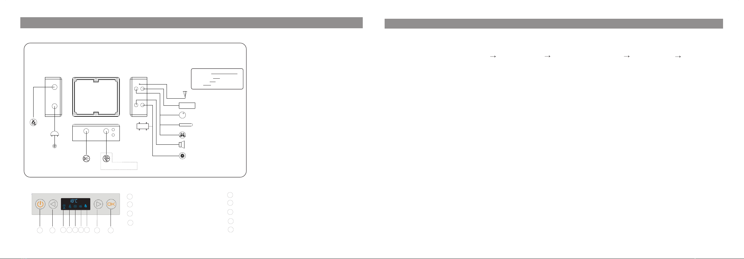
Control panel operation instruction
1. Press any function key would sound a Di Di by buzzer.
2. Power switch
2.1 When press” ”, control system starts operation, also bottom lights are on. When press this key again, control system
shutdown.
2.2 The control system will shutdown automatically after it is opened of 60 minutes.
3. Bottom light
Touch “ 、 ” continuously when the system is on. When the cursor is on the “ ”position, touch “ ” to turn on the
bottom light. Touch “ ” again to turn it off.
4. Child lock
All keys will be locked when no operate the system for 3 minutes, and the screen shows “LOCK”.Press any key for 3
seconds to unlock
all keys, and “LOCK” disappear.
5. Ozone sterilization (this function will be shutdown when the radio is turned on)
5.1 Touch “ 、 ” continuously when the system is on. When the cursor is on the “ ”position, touch “ ” to turn on
the ozone, LCD icon dynamic display. Touch “ ” again to turn it off.
5.2 The ozone will shutdown automatically after it is opened of 10 minutes.
6. Water pump surfing
6.1 There is water level test device in the control system to prevent water pump from running idle to damage water pump under
less water or without water.
6.2 Touch “ 、 ” continuously when the system is on. When the cursor is on the “ ”position, when the device test the
water level has reached to the set valve, touch “ ” to turn on the water pump, LCD icon dynamic display. Touch this key
again to turn it off.
6.3 When water level test device is lower than set valve, the water pump function can not be turn on.
6.4 When water pump is working, water level test device tests it is lower than set valve, water pump will stop working automatically.
If the device tests water level reaches set value, water pump will start working automatically.
7.FM digital radio(this function will be shutdown when the ozone is turned on)
7.1 FM broadcast receiving frequency range is 87.5MHz-180MHz.
15
Control Panel Instruction Control Panel Instruction
Installation Instruction 16

17 Installation Instruction 18
Control Panel Instruction
8.4 Temperature set
8.4.1 When system and thermostat heating function are started, Touch “ ” continuously till it displays
temperature unit ℃, and when it displays temperature value, press or to increase or decrease1 ℃; touch
or for more than 2 seconds the temperature will increase or decrease in the speed of 1℃/ 0.5 second. When
the or do not be touched for 5 seconds, the last setting temperature is the settle temperature. The temperature
shown on the system is the water temperature in the bathtub when the system is exit.
8.4.2 Temperature range: 30℃ - 45℃
8.5 When the temperature sensor is malfunction, the screen shows “E1", and a Di Di comes out. The heater can not be
turned on in this case.
1. User should follow wire diagram and specification instructions strictly to fix the product.
2. Ground wire of controller should be connected to power supply wire in well ground wire condition.
2
3. User should use 3x2.5mm or diameter wider power supply line, which meet national standard (GB); power socket
should be 30A or more than 30A, the air switch or anti-creeping switch should meet national standard (GB). The anti-
creeping switch only uses for assisting.
4. User should use extra 30A or more than 30A, the air switch or anti-creeping switch should meet national standard
(GB). The anti-creeping switch only uses for assisting.
5. Please inspect power line of control box strictly. Connect electricity after confirming.
6. Electrical equipment of illegal manufactures should not be connected to the controller; it is prohibited to take part
product, remodel lines (being sealed) or plug-in components of power box when connect to power voluntarily.
7. Connection lines of power box should follow No. and specification of plug-in components to connect, output lines
should not be connected short circuit.
8. The product should be disconnected to power after using the product in order to avoid accelerating aging by
longtime power connection.
9. Controller installation should strictly following installation instruction to fix by qualified personnel.
10. There is no repairable component in controller, please don’t try to improve by yourself. High voltage of controller
can lead to dangerous, please ask professional personnel to maintain or adjust. If user breaks any operation steps,
our company will not afford any responsibilities.
Notice

19
Maintenance Card
Add
Maintenance Card
Installation Instruction 20
Model No.
Manufacturing
Code
Customer
Name
Tel.
Add.
Agent Shop
Tel.
Purchase Date
Model No.
Purchasing
Date
Manufacturing
Code
Tel
Maintenance item:
1. Every purchase of the series products, get 1 year guarantee by the
maintenance service card and purchasing receipt since the purchasing date.
The following cases are not covered by the warranty.
A. Any damage caused by the misuse, improper maintenance.
B. Installation damage by neither the EAGO agent nor appointed installation
service organization.
C. Without 3 packets "proof, valid bill or proof of purchase.
D. Valid card, maintenance card do not match or alternation.
E. Damage by the irresistibility and irresistible natural calamities.
2. If it is the product quality problem, it will be free maintenance or change the
spare parts.
3. If the problem is not caused by the products itself or
over-exceed the one-year guarantee, it will charge the repairing fees and spare
parts costs.
The first page is kept for the customer.The second page is sent back to EAGO head office.
Maintenance Card
Add
Maintenance Card
Installation Instruction 2 0
The massage
motor or the
air motor can’t
be started.
1. Voltage is abnormal or
electric power is disconnected.
2. The air pressure switch or the
micro pneumatic switch is broken
1. Take off the cover of the jet which
does not workand clean the air pipe.
2. Turn on the air pump.
3. Check the air pump as the air pump
motor failure instruction.
The bathtub
shaking and
‘make noise.
1. The steel stand at bottom
of bathtub is not balance.
2. The fasten screws for
motor and shockproof
rubber is incomplete close.
3. Problem of motor.
1. Adjust the leg to make the steel
stand even.
2. 4 Pieces of screw and 4 shockproof
rubbers shall be provided of the motor.
Fasten the nuts.
3. Contact with your dealer or the
manufacturer.
The pump is
running, but
poor jet
action.
1. The suction net partly
blocked.
2. Not adequate water
level.
3. Adjusting valve of
function is shut down.
4. The inlet pipe of pump
exist air.
5. Other probable cause.
1. Take off the suction net with
screwdriver. Clean it to keep the water
going through smoothly.
2. Pour more water until it over flow the
senor.
3. Open the adjusting valve of function.
4.a) Open the washout valve to exhaust
the air inside the pipe,
b) Check and tighten all connection part
of the inlet pipe.
c) Close the washout valve properly.
5. The water pipe and air pipe may be
mixed up. Please contact the professional
technician to fix it.
1. Plug is off.
2. Control circuit board is
burnt.
Chrometherapy
light doesn’t
work.
Slow water
outlet
1. Supply water pressure
is low.
2. Water inlet block.
1. Check supply water pressure.
2. Clean water inlet filter.
The filter
doesn’t work
1. The rubber ring in the
filter is damage. 1. Change a new one.
Troubleshooting
Solutions
CausesMalfunctions Solutions
Causes
Malfunctions
Some water left
inside the pipe
Some models of bathtub can not drain all water out from the
pipe because of its special construction.
1. Take off the stopper of pop-up water
outlet valve, fasten the screw or adjust
the mandril to the proper place.
2. Replace with new rubber.
3. Dismantle the water outlet, level the
washer and re-install it.
1. Take off the lid of the jet, clean the
small air hole by thin wire.
2. Turn on the air pump.
3. Follow the “air pump does not operate
instruction “process to check the air pump.
1. Air pipe block.
2. Air pump is switch off.
3. Air pump does not operate.
No bubble out
from the
Hydro-massage
jet
The pop-up
water outlet
valve can't
pop-up or it is
leaking
1. The waste cover is leakage,
the screw is loose or the water
divert adjust too low.
2. The pulling cord of water
outlet is broken.
3. The washer is uneven.
This manual suits for next models
2
Table of contents
Other EAGO Bathtub manuals
Popular Bathtub manuals by other brands

Foppapedretti
Foppapedretti Soffietto Karibu Assembly instructions

M-TI
M-TI 112 Installation and operational manual

TR
TR Comfortline Service manual

Mastercare
Mastercare Integrity MB-80R installation manual

Devon & Devon
Devon & Devon Holiday Assembly instructions

Teuco
Teuco HYDROTOP F02 installation instructions

American Standard
American Standard 3052OD.0 Series Installation instructions and owner's manual

Crosswater
Crosswater Duo US-N26CS installation instructions

Fleurco
Fleurco RHAPSODY petite BRH5931 Installation and user guide

Ariel
Ariel ARIEL HW 123 user manual

DURAVIT
DURAVIT Cape Cod 7 0330 Series Mounting instructions

DURAVIT
DURAVIT Paiova 5 Mounting instructions