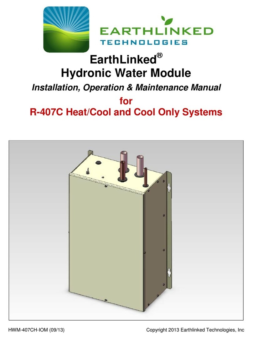
EarthLinked HWM-1836 Instruction manual

HWM-H-IOM (10/14) Copyright 2014 Earthlinked Technologies, Inc
EarthLinked®
Hydronic Water Module
Installation, Operation & Maintenance Manual
for
R-410A and R-407C
Radiant Panel Hydronic Heat Only Systems

HWM-H-IOM (10/14) Page 2
Disclaimer
This manual contains instructions for the EarthLinked®Hydronic Water Module which is
combined with other EarthLinked®system components, field specified hydronic heating
components, thermostats, storage water heaters, storage water tanks and associated
fittings, controls and piping.
EarthLinked®Technologies manufactures and sells only the EarthLinked®system
components and the performance information contained herein is based on performance
of EarthLinked®Technologies’ supplied Products.
Therefore, EarthLinked®Technologies shall not be liable for any defect, unsatisfactory
performance, damage or loss, whether direct or consequential, relative to the design,
manufacture, construction, application or installation of the above mentioned field
specified items.
Proper installation and servicing of the EarthLinked®Heating and Cooling System is
essential to its reliable performance. All EarthLinked®systems must be installed and
serviced by an ETI authorized installer. Installation and service must be made in
accordance with the instructions set forth in this manual. Failure to provide installation and
service by an ETI authorized installer in a manner consistent with the subject manual will
nullify the limited warranty coverage for the system.
Earthlinked Technologies, Inc.
4151 South Pipkin Road
Lakeland, Florida 33811
tel. 863-701-0096 ● fax 863-701-7796
info@earthlinked.com ● www.earthlinked.com
CSI # 23 80 00
IMPORTANT!
FAILURE OF THE INSTALLER TO PROVIDE ADEQUATE ANTIFREEZE
SOLUTION PROTECTION IN EARTHLINKED®RADIANT PANEL
HYDRONIC HEATING AND/OR CHILLED WATER COOLING SYSTEMS
AT THE TIME OF SYSTEM START-UP WILL VOID THE EARTHLINKED®
LIMITED WARRANTY FOR HEATING AND COOLING SYSTEMS.

HWM-H-IOM (10/14) Page 3
Table of Contents
1. Inspection/Pre-Installation........................................................................................................5
A. Inspection .............................................................................................................................5
B. Pre-Installation......................................................................................................................6
2. General System Layout............................................................................................................7
3. Application...............................................................................................................................8
4. The Primary Circuit ..................................................................................................................9
A. Plumbing...............................................................................................................................9
B. Antifreeze Protection...........................................................................................................11
C. Water Quality......................................................................................................................13
D. Storage Water Heater Sizing and Connections..................................................................14
E. HWM Dimensions and Component Information..................................................................14
F. Refrigerant Piping ...............................................................................................................16
5. Controls and Electrical...........................................................................................................17
A. Hydronic Heating Only ........................................................................................................17
B. HWM Freeze Protection Thermostat...................................................................................19
6. Start-Up .................................................................................................................................20
7. Heat Exchanger Maintenance................................................................................................22
8. Tools and Equipment.............................................................................................................26
9. Index......................................................................................................................................27

HWM-H-IOM (10/14) Page 4
List of Figures
Figure 1. Matching Component Model Numbers................................................................................ 5
Figure 2. General Layout of System Components.............................................................................. 7
Figure 3. Typical Radiant Panel Hydronic Heating System ................................................................ 8
Figure 4. Typical HWM Primary Circuit Plumbing............................................................................... 9
Figure 5a. Propylene Glycol Freeze Protection Table..................................................................... 11
Figure 5b. Hydronic System Water Quality Parameters................................................................... 13
Figure 6. Storage Tank Capacities and Pipe Sizes.......................................................................... 14
Figure 7. Hydronic Water Module (HWM) ........................................................................................ 15
Figure 8a. Minimum Water Pipe, Fitting and Strainer Sizes to Storage Water Heater...................... 16
Figure 8b. Flowmeter Kit.................................................................................................................. 16
Figure 8c. (Part 1 of 2) Electrical Field Wiring –Hydronic Heating (HWM)....................................... 17
Figure 8c. (Part 2 of 2) Electrical Field Wiring –Hydronic Heating (HWM)....................................... 18
Figure 8d. Three-Step Electrical Installation for Freeze Protection Thermostat................................ 19
Figure 9. Maximum Operating Conditions (R-410A)......................................................................... 21
Figure 10. Maximum Operating Conditions (R-407C) ...................................................................... 21
Figure 11. Minimum Heat Exchanger Water Flow Rates.................................................................. 22
Figure 12. Minimum Heat Exchanger Propylene Glycol/Water Solution Flow Rates ........................ 23
Figure 13. HWM Heat Exchanger Cleaning Set-up.......................................................................... 24

HWM-H-IOM (10/14) Page 5
1. Inspection/Pre-Installation
A. Inspection
Upon receipt of the equipment, carefully check the shipment against the bill of lading. Reference
EarthLinked®matching system component model numbers in Figure 1. Make sure all units have
been received and model numbers are the same as those ordered.
Compressor Unit
Hydronic Water Module
-018, -024, -030, -036
HWM-1836
-042, -048
HWM-4248
-054, -060, -068, -072
HWM-5472
Figure 1. Matching Component Model Numbers
Inspect the carton or crating of each unit, and inspect each unit for damage. Assure the carrier
makes proper notation of any shortages or damage on all copies of the freight bill and he
completes a common carrier inspection report. Concealed damage not discovered during
unloading must be reported to the carrier within 15 days of receipt of shipment. If not filed
within 15 days, the freight company can deny the claim without recourse. Note: it is the
responsibility of the purchaser to file all necessary claims with the carrier.
Equipment should be stored in its packaging in a clean, dry area. Store equipment in an upright
position at all times. Equipment is to be stacked in accordance with the notation on the
packaging. DO NOT remove equipment from shipping cartons until equipment is required
for installation.
Cover equipment on the job site with either shipping cartons, vinyl film or an equivalent
protective covering. In areas where painting, plastering and/or spraying has not been completed,
all due precautions must be taken to avoid physical damage to the equipment and contamination
by foreign material. Physical damage and contamination may prevent proper start-up and may
result in costly equipment clean up. Examine all equipment before installing.
IMPORTANT!
The hydronic water modules listed below can be used in HEAT ONLY
applications
Warning!
WEAR ADEQUATE PROTECTIVE CLOTHING AND PRACTICE ALL
APPLICABLE SAFETEY PRECAUTIONS WHILE INSTALLING THIS
EQUIPMENT. FAILURE TO DO SO MAY RESULT IN EQUIPMENT
AND/OR PROPERTY DAMAGE, PERSONAL INJURY OR DEATH.
Warning!
WEAR ADEQUATE PROTECTIVE CLOTHING AND PRACTICE ALL APPLICABLE SAFETEY PRECAUTIONS
WHILE INSTALLING THIS EQUIPMENT. FAILURE TO DO SO MAY RESULT IN EQUIPMENT AND/OR
PROPERTY DAMAGE, PERSONAL INJURY OR DEATH.

HWM-H-IOM (10/14) Page 6
B. Pre-Installation
Prior to installing the Hydronic Water Module and other EarthLinked®space heating and
cooling system above-ground components, you will need tools and equipment listed in
Section 8 to properly install the system.
Installation of the Hydronic Water Module must be done in accordance with this manual.
Prepare the Hydronic Water Module (HWM) for installation as follows:
1. Compare the data on the unit nameplate or packaging with ordering and shipping
information to verify the correct unit has been shipped (See Figure 1.)
2. Keep the HWM covered with the packaging until installation is begun and all plastering,
painting, etc. is finished.
3. Verify refrigerant tubing is free of kinks or dents.
4. Inspect all electrical connections. Connections must be clean and tight at the terminals.
IMPORTANT!
To avoid equipment damage, DO NOT use this equipment as a source of
heating or cooling during the construction process. The mechanical
components may become clogged with construction dirt and debris
which may cause system damage.

HWM-H-IOM (10/14) Page 7
2. General System Layout
Guidelines for the general layout of the Hydronic Water Module and other EarthLinked®system
components are shown in Figure 2.
Figure 2. General Layout of System Components

HWM-H-IOM (10/14) Page 8
3. Application
Typical application of the Hydronic Water Module to radiant panel hydronic heating is
illustrated in Figure 3.
Figure 3. Typical Radiant Panel Hydronic Heating System
IMPORTANT!
This HWM series hydronic water module may be utilized with R-104A and R-
407C systems when the only function is to heat hydronic water. See example
above. It cannot be utilized with R-410A or R-407C systems when its
function is to chill water.

HWM-H-IOM (10/14) Page 9
4. The Primary Circuit
A. Plumbing
The primary circuit in a typical HWM installation is shown in Figure 4.
Figure 4. Typical HWM Primary Circuit Plumbing
IMPORTANT!
The hydronic water module (HWM) is to be mounted on a wall or fixed
rigidly in place. The HWM is to be placed no more than 10 FEET AWAY
FROM THE STORAGE WATER HEATER. Orient the HWM with “pipes
up” only. All interconnecting water piping between the HWM and the
water tank are to be insulated with ½” wall thickness Armflex®, Insul-
Lock®or the equivalent insulation.

HWM-H-IOM (10/14) Page 10
The components are as follows:
1. Flowmeter: Model ETI-A1-116000-1 hydronic water/antifreeze solution flowmeter is
available from ETI and is field calibrated for the specific antifreeze mixture. The kit
includes calibration equipment.
2. Strainer: Models ST-1836 (for 1.5 thru 3.0 ton systems) and ST-4272 (for 3.5 thru 6.0
ton systems) are 20 mesh, brass, inline strainers, available from ETI and necessary
to trap particles and maintain proper flow through the brazed plate heat exchanger
channels.
3. Temperature Controller: Model HHK-1872 is a hydronic heating controller. This
controller can be mounted remotely and comes with a capillary tube 6 feet long,
thermal bulb, thermal paste and the NPT thermal well insert and is available from ETI.
4. Storage Water Heater: The GSTE Series storage water heaters are available from
ETI in 60, 80 and 119 US Gallon capacities, and are designed for use with the
EarthLinked®geothermal systems. They are equipped with a 4.5 kW supplemental
heater which satisfies the ETI requirement for a minimum of 20% supplemental heat.
5. Other Plumbing Components and Parts: Gate valves, unions, copper pipe, pipe
insulation, etc. meeting USA industry and local code standards are commercially
available through plumbing supply outlets.
All plumbing installations are to be in accordance with the applicable local and
national codes.
To protect the brazed plate heat exchanger from damage during cooling operation
when the heat exchanger is producing chilled water, a factory installed thermal switch
at the outlet of the heat exchanger will turn the compressor OFF when the chilled
water temperature drops to 38°F.
WARNING!
The heat exchanger must be isolated from the water system when the
system undergoes a “superchlorination” or “shock chlorination”
flushing process. Closing the isolation valves as shown in Figure 4
prior to initiating the system flushing process isolates the heat
exchanger. The water entering the heat exchanger after the system
flushing must not exceed a chlorine level consistent with the local
municipal water purification standards. Failure to isolate the heat
exchanger will damage the heat exchanger causing system failure.
Allowing highly chlorinated water to enter the heat exchanger will void
the EarthLinked®Limited Warranty.

HWM-H-IOM (10/14) Page 11
B. Antifreeze Protection
When the HWM hydronic water module is applied to radiant panel hydronic heating, the water
circulating system must be protected from potential damage due to freeze-up by utilizing an
adequate antifreeze solution. The antifreeze protection is provided by the installer prior to the
EarthLinked®system start-up.
Propylene-glycol antifreeze solution with an inhibitor is the type of antifreeze solution required
for EarthLinked® products utilized in radiant panel hydronic heating systems. These systems
shall be freeze protected consistent with the application-specific minimum temperature, as
shown in the table below. Propylene-glycol antifreeze solutions should always be in the range of
20% to 50% by volume, as indicated in the Figure 5a.
TEMPERATURE, °F
PROPYLENE GLYCOL, %
WATER SOLUTION
MULTIPLIER FACTOR (WSMF)
18
20
x 1.03
8
30
x 1.07
-7
40
x 1.11
-29
50
x 1.16
Figure 5a. Propylene Glycol Freeze Protection Table
Propylene-glycol can be purchased in the straight form and mixed with an inhibitor prior to filling
the system, or it can be purchased as inhibited propylene-glycol. The following are examples of
manufacturers for the above:
WARNING!
ALWAYS REMOVE THE ANODE ROD(S) FROM THE STORAGE WATER
TANK OR HEATER UTILIZED IN A RADIANT PANEL HYDRONIC
HEATING AND/OR COOLING SYSTEM. IF THE ANODE ROD(S) ARE NOT
REMOVED, THE PROPYLENE-GLYCOL SOLUTION WILL REACT WITH
THE ANODE ROD(S) TO CREATE PARTICLES THAT BLOCK FLOW AND
CAUSE SYSTEM FAILURE.
IMPORTANT!
Because addition of propylene-glycol to water changes the specific heat
of water, the required flow rate of propylene-glycol solution (for the
same heat transfer as water) must be increased by the water solution
multiplier factor shown in the table above. See Section 7 for details.
IMPORTANT!
FAILURE OF THE INSTALLER TO PROVIDE ADEQUATE ANTIFREEZE
SOLUTION PROTECTION IN EARTHLINKED®RADIANT PANEL
HYDRONIC HEATING SYSTEMS AT THE TIME OF SYSTEM START-UP
WILL VOID THE EARTHLINKED®LIMITED WARRANTY FOR HEATING
AND COOLING SYSTEMS.

HWM-H-IOM (10/14) Page 12
Straight propylene-glycol: Chemical Specialties, Inc. (www.chemicalspec.com/spg.html)
Inhibitor: Nu-Calgon Products, Ty-lon B20 (www.nucalgon.com/products)
Inhibited propylene-glycol: Houghton Chemical Corp., SAFE-T-THERM®,
www.houghton.com/fluids/safe-t-therm/index.html)
General guidelines for introducing propylene glycol into the water circulating system follow. The
manufacturer’s specific instructions and industry standards always take precedence when
introducing propylene-glycol to the system.
Calculate the quantity of inhibited propylene-glycol (fluid) required to achieve the
desired results.
Introduce a sufficient quantity of water to the system and pressure check to ensure a
sealed system.
Drain some water from the system to provide enough volume for the calculated
amount of fluid.
Add the correct amount of fluid and any water needed to completely refill the system,
allowing for liquid expansion due to operating temperature.
Circulate the inhibited propylene-glycol antifreeze solution for at least 24 hours to
ensure complete mixing. Check the liquid concentration to assure that the correct
mixture is obtained.

HWM-H-IOM (10/14) Page 13
C. Water Quality
Water quality in hydronic systems is important to the life and efficiency of the system. Water of
poor quality can cause a decrease in heat transfer ability and cause leaks.
Ensuring proper quality water is a key step in the installation of the hydronic water module
(HWM) and circulating water system.
Water quality parameters and the recommended ranges are listed in Figure 5b. The antifreeze
manufacturer’s water quality requirements take precedence over the ranges listed in Figure 5b.
Parameter
Optimal Conditions
Comments
Glycol Freeze
Protection
20% to 50%
Below 20% can promote the growth of bacteria.
Concentrations higher than 50% will dramatically reduce the
heat transfer ability. Glycol seepage can occur at o-rings
and seals.
Corrosion inhibitor
Molybdate inhibitor
or
Nitrite inhibitor
100-150ppm
800-1200ppm
Without the addition of Nitrite or Molybdate inhibitors,
corrosion of the metallic components will begin and
eventually lead to leaks.
pH
9-10.5 pH units
A pH below 9.0 will allow the corrosion of steel and above
10.5 will allow the corrosion of brass and copper.
Conductivity
700-3200µS/cm
Conductivity above 3500µS/cm will cause the water to
become physically abrasive and damage the o-rings.
Addition of chemicals to the water will raise the conductivity.
Hardness
100-300ppm
Artificially soft water can be aggressive to the system. The
use of unsoftened water is recommended. Do not use
distilled or purified water.
Bacteria/Mold
No Bacteria or
Mold
The growth of bacteria will cause erosion of seals and the
deposit of a bacterial slime will clog the system. Bacteria can
attack the o-rings and cause premature failure. Glycol above
20% will kill any bacteria.
Figure 5b. Hydronic System Water Quality Parameters
IMPORTANT
THE SERVICES OF A QUALIFIED WATER TREATMENT SPECIALIST
ARE REQUIRED FOR THE APPROPRIATE WATER ANALYSIS AND
TREATMENT.
IMPORTANT
THE SERVICES OF A QUALIFIED WATER TREATMENT SPECIALIST
ARE REQUIRED FOR THE APPROPRIATE WATER ANALYSIS AND
TREATMENT.
IMPORTANT!
Always follow the propylene-glycol manufacturer’s instructions
concerning the water quality specifications before filling the water
circulating system.

HWM-H-IOM (10/14) Page 14
D. Storage Water Heater Sizing and Connections
Storage water heaters are necessary with EarthLinked®radiant panel hydronic heating systems,
as typically illustrated in Figures 3 and 4.
ETI Models 60, 80 or 119 GSTE storage water heaters are configured specifically for hydronic
heating and meet all requirements for these applications.
Recommended water storage tank capacities are shown in Figure 6, based on the nominal
tonnage of the compressor unit specified.
Compressor Unit
Model/Capacity,
BTUH
HWM
Model
ETI Storage
Water Heater Size,
US Gallons
ETI Storage
Water Heater
Element Rating, kW
Minimum Nominal
Type L Hard Copper
Pipe & Fittings, inches
-018/18,000
-1836
60
4.5
3/4
-024/24,000
-1836
60
4.5
3/4
-030/30,000
-1836
60
4.5
1
-036/36,000
-1836
60
4.5
1
-042/42,000
-4248
80
4.5
1-1/2
-048/48,000
-4248
80
4.5
1-1/2
-054/54,000
-5472
80
4.5
1-1/2
-060/60,000
-5472
80
4.5
1-1/2
-072/72,000
-5472
80
4.5
1-1/2
Figure 6. Storage Tank Capacities and Pipe Sizes
E. HWM Dimensions and Component Information
The Hydronic Water Module physical dimensions as well as water solution piping connections
are illustrated in Figure 7.
IMPORTANT
A STORAGE WATER HEATER USED FOR HYDRONIC HEATING MUST
BE EQUIPPED WITH SUPPLEMENTAL ELECTRIC HEATING WITH A
RATING OF AT LEAST 20% OF THE DESIGN HEATING LOAD. FAILURE
TO DO SO WILL VOID THE EARTHLINKED®HEATING AND COOLING
SYSTEM LIMITED WARRANTY.

HWM-H-IOM (10/14) Page 15
Figure 7. Hydronic Water Module (HWM)

HWM-H-IOM (10/14) Page 16
Figure 8a lists the minimum nominal Type L hard copper pipe and fitting sizes, and the strainer
required for the primary circuit between the hot water module (HWM) and the storage water
heater.
Compressor Unit Size
& Capacity, BTUH
HWM/DWM
Models
Minimum Nominal Type L
Hard Copper Pipe and
Fittings, Inches
ETI Strainer
Model, Size
-018 (18,000)
-1836
3/4
ST-1836
1in. FPT
-024 (24,000)
3/4
-030 (30,000)
1
-036 (36,000)
1
-042 (42,000)
-4248
1-1/2
ST-4272
1-1/2in FPT
-048 (48,000)
1-1/2
-054 (54,000)
-5472
1-1/2
-060 (60,000)
1-1/2
-072 (72,000)
1-1/2
Figure 8a. Minimum Water Pipe, Fitting and Strainer Sizes to Storage Water Heater
The flow meter illustrated in Figure 4 is an important component of the system to (1) commission
the performance of the system at startup and (2) determine when maintenance to the system
strainer and/or HWM heat exchanger is required. (See Maintenance in Section 7.)
ETI part number ETI-A1-116000-1 flowmeter kit has a range of 5-50 GPM and can be field
calibrated for the appropriate antifreeze mixture for the specific application. The kit includes the
flowmeter and the 5 gallon calibration container.
The flow meter kit (see Figure 8b) may be purchased at http://www.buygpi.com/eti-a1-116000-
1.aspx.
Figure 8b. Flowmeter Kit
F. Refrigerant Piping
Refrigerant piping connections and line set sizes are listed in Figure 7.
IMPORTANT!
Maximum hot water temperature, from the Hydronic Water Module is 110°F.

HWM-H-IOM (10/14) Page 17
5. Controls and Electrical
A. Hydronic Heating Only
The electrical field wiring for the HHK-1872 temperature controller and the electric heat element
and thermostat are illustrated in Figure 8c (Part 1 of 2) and Figure 8c (Part 2 of 2).
Figure 8c. (Part 1 of 2) Electrical Field Wiring –Hydronic Heating (HWM)
IMPORTANT
When the Hydronic Water Module (HWM) is being installed with an SC or
SD Series Compressor Unit, the following Pump Wire Kit must be field
installed:
PW1-1872 for 230/208-1-60 and 230/208-3-60 power supply

HWM-H-IOM (10/14) Page 18
Figure 8c. (Part 2 of 2) Electrical Field Wiring –Hydronic Heating (HWM)

HWM-H-IOM (10/14) Page 19
B. HWM Freeze Protection Thermostat
1. The freeze protection thermostat is factory installed. The thermostat wiring must be
connected when the HWM is installed. Run the wire through the electrical port in the top
panel of the Hydronic Water Module cabinet. After attaching the wire to the switch terminals,
run it into the Compressor Unit (using a control wiring port), in accordance with applicable
electrical codes.
2. Once the freeze protection switch wire leads are inside the Compressor Unit, locate the lock-
in relay in the Compressor Unit electric box.
3. Proceed to make the electrical connections as shown in the three steps illustrated in Figure
8d. Check all electrical connections to ensure a tight fit and good contact.
Figure 8d. Three-Step Electrical Installation for Freeze Protection Thermostat
4. Replace the cabinet cover to the HWM Hydronic Water Module.
5. If the water solution temperature drops to 38°F, the pre-set switch will trigger and cause the
lock-in relay to terminate power to the compressor. The system requires a manual restart.
6. Follow the Start-Up Procedure in Section 6.

HWM-H-IOM (10/14) Page 20
6. Start-Up
The following conditions must be met before starting the HWM:
The toggle switch on the HWM cabinet must be “OFF”.
The system has been charged according to instructions.
Heating elements in the hot water storage tank are “OFF”.
Temperature of water in hot water storage tank is less than 100°F.
HWM pump is primed and tank water pressure is normal.
Gage manifold set is connected to high and low pressure connections on the compressor
unit.
The storage water heater temperature,controller is adjusted to the highest desired water
temperature,setting (110°F maximum).
An accurate temperature,sensor is connected to the “Water Out” tube of the HWM and
insulated from ambient air temperature.
The HWM start-up steps are as follows:
1. Turn the HWM toggle switch to “ON”.
2. Start system running and monitor compressor discharge pressure and HWM “Water Out”
temperature,as water temperature,rises.
3. If compressor discharge pressure reaches 475 psig (R-410A) or 350 psig (R-407C) before
desired hot water temperature,is achieved, adjust the storage tank temperature,controller
setting to turn the compressor off, or (next):
4. When “Water Out” temperature,is achieved (pressure < 475 psig for R-410A or < 350 psig
for R-407C), adjust water storage tank temperature,controller to turn compressor unit
“OFF”. Reference Figures 9 and 10.
5. The water storage tank temperature,controller setting should be verified by draining some
hot water from the tank and cycling the system again.
This manual suits for next models
2
Table of contents
Other EarthLinked Water System manuals
Popular Water System manuals by other brands

oventrop
oventrop OVSOL System 5 manual

AquaPur
AquaPur VALROM Espresso 600GPD manual

Viqua
Viqua Hi-Flo instruction sheet

Yamato
Yamato Neocool CF302L-A instruction manual

STIEBEL ELTRON
STIEBEL ELTRON SBB 400 S Operating and installation instruction

Riello
Riello 7200 Kombi Plus Installation, operation and maintenance manual

Zip
Zip HydroTap G4 Installation and operating instructions

Aqua Cooler
Aqua Cooler AC-M8WREBFY Usage and Care Manual

Julabo
Julabo 9021713.S1.02 Original operating manual

Liberty Pumps
Liberty Pumps Pro680 Series installation manual

Everpure
Everpure SSFM-100BC-SYS Specification sheet

Riello
Riello RIELLO 7200/3F-800 HV PLUS installation instructions