EAST Group 9010 User manual


CATALOG
Chapter 1: Introduction.......................................................................................................................1
1.1 Brief Introduction of Performance Features ......................................................................1
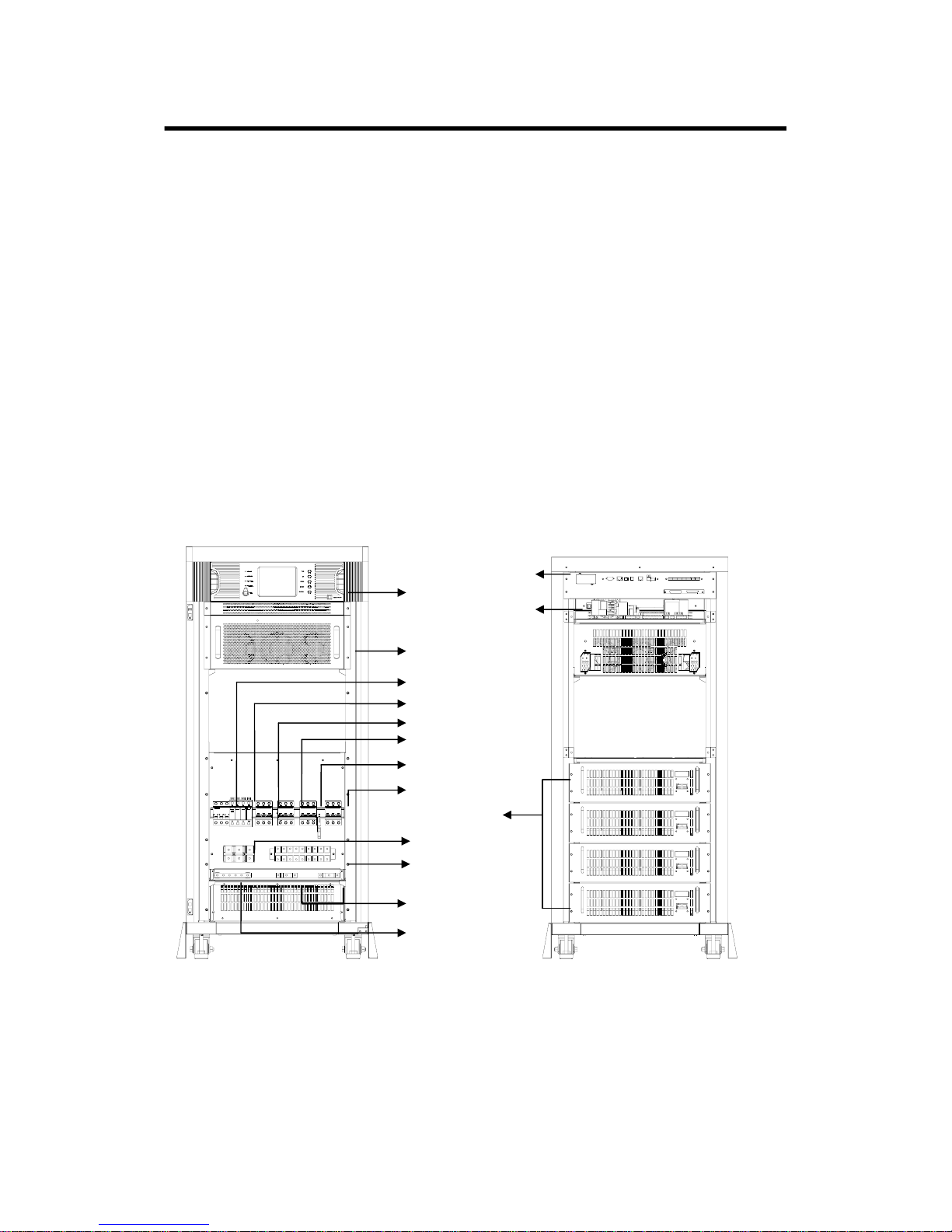
1.2 System Structure....................................................................................................................1
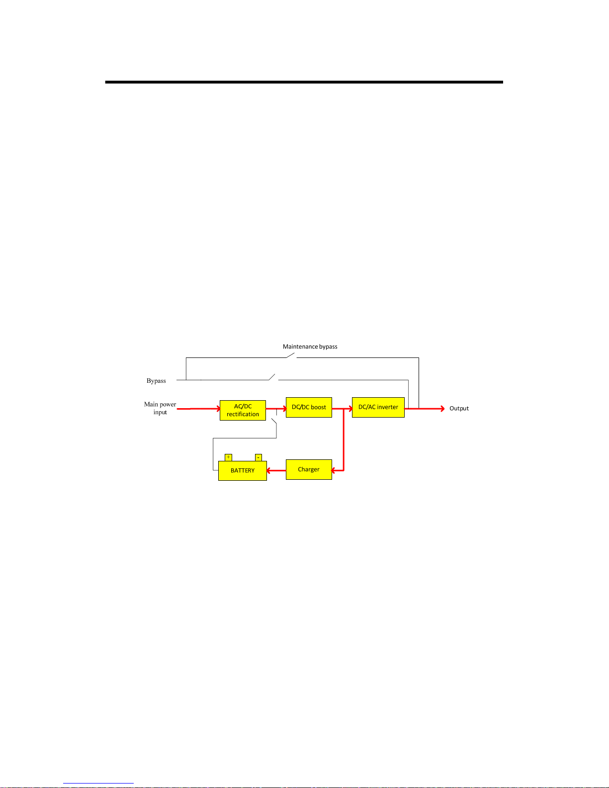
1.3 Operating Mode......................................................................................................................3
1.4 Functions and Characteristics...............................................................................................5
Chapter 2: Installation Instruction.....................................................................................................7
2.1 Unloading and Unpacking.....................................................................................................7
2.2 Site Selection..........................................................................................................................8
2.3 Installation of UPS .................................................................................................................8
2.4 Cable Selection and Connection ..........................................................................................9
2.5 Battery Connection..............................................................................................................13
Chapter 3:Operation........................................................................................................................17
3.1 Introduction of Operation Interface..................................................................................17
3.2 Operation for Power on of Single Machine (10-60KVA for example)...................18
3.3 Operation for Power off......................................................................................................26
3.4 Operation for Emergency Power off..................................................................................27
3.5 Operation for Maintenance Bypass....................................................................................28
3.6 Enquiry Operation................................................................................................................29
3.7 Operations for User Configuration.....................................................................................36
Chapter 4: Installation and Operation of Paralleled Machine ......................................................49
4.1 Installation of Paralleled System .......................................................................................49
4.2 On/Off of Paralleled Machines............................................................................................50
4.3 Enquire Operation of Paralleled System...........................................................................52
Chapter 5: UPS Repairing and Maintenance...................................................................................53
5.1 UPS Repairing and Maintenance........................................................................................53
5.2 Troubleshooting ...................................................................................................................55
5.3 Maintenance Assurance ......................................................................................................58
5.4 Technical Specifications......................................................................................................58
Appendix 1: Lamp Signal Reference List.........................................................................................61
Appendix 2: Port of Communication Interface...............................................................................63
Appendix 3: Dial Switch Set of Module and Charger.....................................................................66

PREFACE
Thankyouforusingourproducts.
Ourcompanyisengagedindevelopingandmanufacturingproductsofuninterruptedpowersystem
whichisakindofpowerproductwithhighqualityandcanmeetvariousperformancerequirements.
Note:
Thismanualcontainsinstructionofmounting,application,andoperationofUPS.Itshallreadthis
manualcarefullybeforemountingthesystemanditisnotallowedtotakeanyoperationsonUPS
beforefinishingreadingallsafetyinstructionandoperationinstruction.Thismanualcontains
significantinformation,pleaseobeyallwarningsandoperationinstructionsstatedbythemanual
andmachine,andthemanualshallbekeptwell.
Safety:
Theuninterruptedpowersystemmustbegroundedbeforeoperation.
Batteryshallbereplacedbyqualifiedmaintenancepersonal.Thebatteryistoxicwasteaccordingto
laws,sowastedbatteryshallberecoveredbyitsclassificationinaccordancewithrequirementof
environmentalprotection.
Warning:
SellingofthisproductisonlyforpartnerwhohasgeneralinformationonUPSproducts.Itis
necessarytoknowsomeothermountingrequirementsormeasurestopreventaccident.
Anycontentofthemanualshallnotbemodifiedwithoutallowanceofmanufacturerandany
offendersmustbeinvestigated.Ourcompanyreservestherightoffinalinterpretation.

Change History
Changesbetweendocumentissuesarecumulative.Thelatestdocumentissue
containsallthechangesmadeinearlierissues.
IssueV_02(2014‐04‐10)
ComparedwithV01version,themodifiedcontentsareasfollows:
1. Deletethecontentsofunpackingmodulepackage.
2. Increasethedescriptionsof80‐120KVAbasedonIssueV_01.
3. Increasethewayofsetting+15piecesofbattery.
4. Increasethefunctionofinputdrycontact.
5. ChangethenumberofdialswitchofmoduleID,4pinto5pin.
6. UpdatesomepicturesbasedonIssueV_01.
IssueV_01(2012‐11‐30)
Thisisthefirstrelease.

10-120KVA (3/3) UPS user manual
- 1 -
Chapter 1: Introduction
1.1 Brief Introduction of Performance Features
10‐120KVA(3/3)seriesisakindofhigh‐frequencyUPSwiththree‐inletandthree‐outletdesignedby
fulldigitalcontroltechnology.Thedesignofunitbreaksconventionaldesignthoughtoftower‐type
machine,replacedbyadvancedmodulardesignideawhichcanensurecompactnessoflayoutand
improvereliabilityoftheunit.Electricalperformanceof10‐120KVA(3/3)seriesisadvantageousand
protectionofsoftwareandhardwareofitisperfect.Itisapplicablefordifferentpowergridandcan
supplysafeandreliablepowerfordifferentloads.
1.2 System Structure
Componentsofthesystemmainlyinclude:LCDdisplayscreen,communicationport,powermodule,
charger,battery(optional),inputbreaker,outputbreaker,maintenancebypassbreaker,groundrow,
Nrow,andsoon.Itssystemstructurechartisshowninfigure1.1,figure1.2andfigure1.3.
Front(withoutbaffle) Back
Figure1.1Structureof10‐30KVAseries
1. communication
p
ort
2. LCD dis
p
la
y
scree
n
4. power module
3. Char
g
e
r
11. Battery pack
5. SPD breaker
(
o
p
tional
)
6. SPD(optional)
7. Input breaker
8. Bypass breaker
9. Maintenance
byp
ass breake
r
10. Output breaker
12. Terminal block
of batter
y
13. Terminal block of
input,bypass and output
14. Terminal block of
ground
15. Terminal block
of N

10-120KVA (3/3) UPS user manual
- 2 -
Front(withoutbaffle) Back
Figure1.2Structureof40‐60KVAseries
SPD Breaker Surge Prot ectionDevice
1.Communication port
2.LCD display screen
4.Charger
11.Input breaker
10.Bypass breaker
9.Maintenance bypass
breader
8.Output breaker
6.SPD(Optional)
7.SPD breaker(Optional)
5.Charger(Optional)
3.Power module
Front(without baffle) Back
Figure1.3Structureof80‐120KVAseries
1.Communication port
2. LCD display screen
3.Power module
4. Charger
5. SPD breaker
(
o
p
tional
)
6. SPD
(
o
p
tional
)
7. In
p
ut breaker
8.Out
p
ut breake
r
9. Maintenance bypass breaker
10. Bypass breaker
11. Terminal block of
input,bypass and output
12. Terminal block of battery
13. Terminal block of ground
14. Terminal block of N

10-120KVA (3/3) UPS user manual
- 3 -
1.3 Operating Mode
10‐120KVA(3/3)isakindofonlinedouble‐conversionUPS,itsoperatingmodesareasfollows:
zMainpowersupplymode
zBatterymode
zBypassmode
zMaintenancemode(manualbypass)
zFrequencyconvertermode
1.3.1 Main power mode
TheworkingmodethatalternatingcurrentpowerofrectifiercircuitforUPSissuppliedbymain
power,directcurrentpowerforinverterissuppliedaftercorrectedbyPFCpowerfactor,and
continuousanduninterruptedalternatingcurrentpowerforloadisprovidedbyinvertercircuitis
calledmainpowermode.Thechargerwillstartautomaticallyafterpoweronofinvertertosupply
powerforbattery.
Figure1.4WorkingProcessChartunderMainPowerMode
1.3.2 Battery mode
Theworkingmodethatbatterypowerisboostedthroughbatteryboostercircuit,andthensupplied
toloadthroughinvertercircuitiscalledbatterymode.Whenmainpowerfaultoccurs,thesystemwill
switchtobatterymodeautomaticallyandpowersupplyforloadisnotinterrupted.Whenmain
powerrecoveries,thesystemwillswitchtomainpowermodeautomaticallywithoutanymanual
operationandpowersupplyforloadisnotinterrupted.Switchingtimeofmainpowermodeand
batterymodeis0ms.

10-120KVA (3/3) UPS user manual
- 4 -
AC/DC
rectification
Charger
DC/DCboost
BATTERY
+ -
DC/ACinverter Output
bypass
Maintenancebypass
Mainpowe
input
Figure1.5WorkingProcessChartunderBatteryMode
1.3.3 Bypass mode
Iffault,suchasinvertercircuitfaultandinvertercircuitoverload,orswitchingtobypassmodeby
handoccurs,theUPSwillswitchtheloadfromsideofinvertertosideofbypassandpowersupplyfor
theloadisnotinterrupted.
Figure1.6WorkingProcessChartunderBypassMode
1.3.4 Maintenance mode (manual bypass)
IfitneedstomaintainorrepairtheUPS,itcanclosethemanualbypassswitchtoswitchtheUPSto
thesideofmaintenancebypassandthepowersupplyforloadisnotinterrupted.Inthatcase,the
mainpowerwillnotpasstheinternalcomponentsofmachinebutconnecttheinputterminaland
outputterminaldirectlysothatwecanmaintainorrepairtheUPS.

10-120KVA (3/3) UPS user manual
- 5 -
Figure1.7WorkingProcessChartunderMaintenanceBypassMode
1.3.5 Frequency converter mode
UPScanbesettofrequencyconvertermodewhichcanprovidestableoutputfrequencyof50Hzor
60Hz.Inputfrequencyrangeofmainpoweris40Hz~70Hz.UPSwilloutputthesetoutput
frequencyandthebypassmodeisineffectiveunderfrequencytransformermode.Whenmainpower
isabnormal,thesystemwillswitchtobatterymodeautomaticallyandstilloutputwiththesetoutput
frequency.
1.4 Functions and Characteristics
zDSPfulldigitalcontroltechnology;
zPureonlinedouble‐conversionframework,strongloadcapability;
zInputpowerfactorisashighasmorethan0.99,lowharmoniccurrent,environmental
protection,high‐efficient,andenergysaving;
zWideinputvoltagerange,50/60Hzpowersystemself‐adoptionsuitableforallgridunder
anycircumstance;
zSupportfrequencymodesof50Hzinput/60Hzoutputand60Hzinput/50Hzoutputwhich
canmeetspecialrequirementsofuser;
zAdvanced“N+X”wirelessparallelconnectionredundanttechnique,highparallelreliability
andsmallcirculation;
zParallelmachinessharethebatterygroupwhichcansavecellinvestmentfromuser;
zDigitalchargerwithflexiblechargingparametersetandbatterypiecesselection;
zAdvancedbatteryintelligentmanagementtechnologywhichcanprolongworkinglifeof
batteryeffectively;
zSupportcoldstartofbatteryandautomaticstartofnormalpowerwhichcanmeetuser’s
applicationrequirements;
zEasilydamagedcomponentsarecompletelyisolatedwithairfluewhichcanimprove
reliabilityofthesystemeffectively;

10-120KVA (3/3) UPS user manual
- 6 -
zEasilydamagedcomponentscanbechangedinmodulelevel,fieldreplacementisfastand
convenientandmodulecostislow;
zPerfecthardwareandsoftwareprotectionfunction(breaker,Fuse,hardwareprotection,and
softwareprotection),superselfdiagnosis,andrichhistoricrecordenquiry;
z5.7inchLCDtouchwidescreendisplay,friendlyhuman‐machineinterface;
zManycommunicationports,includingRS232,RS485,USB,drycontactcardandSNMPsmart
cardtrough.

10-120KVA (3/3) UPS user manual
- 7 -
Chapter 2: Installation Instruction
2.1 Unloading and Unpacking
Usershallcheckthepackagetoconfirmitisundamagedafterreceivingtheproduct;thenopenthe
packagetocheckwhethertheequipmentisundamaged,andpleasecontactthecarrieratonceifitis
damaged.
2.1.1 Open of cabinet package
1)Putthepackingboxvertically;
Figure2.1PackingBoxPlacements
2)Openthetopplateofpackingboxandthentakeoutthefoam;
Figure2.2UnsealthePackingBox

10-120KVA (3/3) UPS user manual
- 8 -
3)Unsealsideplatesofpackingboxandthentakeoutthefoams.
Figure2.3UnsealedCabinet
Tips:Itshallbecarefulwhenunsealingtopreventscratchforthemachinebody.
Checkwhetherthequalifiedcertificate,instructionbook,CDdisk,andkeysforfrontandbackdoors
arecompleteornotafteropeningthepackingbox.
2.2 Site Selection
zPlacedlocationmustbestable;
zEnoughventilationspacemustbeleftbetweenallsurfacesofUPSandwalls;
zBefarawayfromhotsourceandcorrosivematerials,avoidthesunshine;
zKeepnormalworkingtemperatureandelevationheight(workingtemperature:0℃~40℃,
itneedstobeappliedbyderatingifelevationheightexceeds1500m);
zKeepcleanworkingenvironment,avoidenvironmentwithmoisture,flammablegas,
flammableliquid,orcorrosivematerial;
zWeightcapabilityoffloortomachineandbatterygroupshallbeconsideredbeforemounting.
2.3 Installation of UPS
LocationofplacingtheUPSshallbeproperinordertoensuresafetyapplicationofUPS.Itshallbe
placedinplacewithcleanenvironmentwithoutmoisture,flammablegas,flammableliquidor
corrosivematerialandsunshine.Usercanputitonassignedlocationwithassistantofhumanforceor
equipmentandshallpayattentiontospacesbetweenUPSandsurroundingthingswhenmounting
sothatitishelpfulforventilationandheatdissipation.Minimumspaceisshowninfigure2.4(unit:
mm):

10-120KVA (3/3) UPS user manual
- 9 -
Figure2.4CabinetPlacementChart
2.4 Cable Selection and Connection
2.4.1 Selection of cable
Whenselectingconnectingcableforthesystem,itissuggestedtoselectthewirediameterofcable
accordingtomaximumpowerconfigurationof10‐120KVAsystemandcomplyinglocalconnection
rulesandenvironmentalcondition(temperatureandphysicalsupportmedia).Thecableshallbe
selectedaccordingtomaximumsteady‐statealternatinganddirectcurrentsof10‐120KVA,andits
selectionconditionsarelistedintable2.1:
Table2.1CableConfigurationTable
UPSratedpower
Rated380VinputDischarging
currentof32
piecesbatteries
Inputcurrentwhenitisfull
loadandchargeroutputs
maximumpower
Output
currentwhen
itisfullload
10KVA24A15A28A
15KVA31A23A41A
20KVA39A30A55A
30KVA53A46A83A
40KVA78A61A110A
60KVA117A91A165A
80KVA156A121A220A
100KVA195A151A275A
120KVA234A182A330A

10-120KVA (3/3) UPS user manual
- 10 -
2.4.2 Connection of cable
Batteryinput(long‐termmachine),mainpowerinput,bypassandoutputcableshallbeconnected
withUPSaccordingtothepathsshowninFigure2.5andfigure2.6.
Figure2.5InletandOutletWiringChannelof10‐60K
Figure2.6InletandOutletWiringChannelof80‐120K
Connectionofcableis:
1)Openthedistributionboardtoexposethecopperrows.
Figure2.7FrontViewof10‐30KVA

10-120KVA (3/3) UPS user manual
- 11 -
Figure2.8FrontViewof40‐60KVA
Figure2.9FrontViewof80‐120KVA

10-120KVA (3/3) UPS user manual
- 12 -
2)Phasesshowninfollowingfigurearelineterminalsofmainpowerinput,bypassinput,battery
inputandoutputcableafterpassingtheinletandoutletwiringchannels.
Figure2.10DistributionWiringDiagramof10‐30KVAseries
Figure2.11DistributionWiringDiagramof40‐60KVAseries

10-120KVA (3/3) UPS user manual
- 13 -
Figure2.12DistributionWiringDiagramof80‐120KVAseries
Tip:pleasetightentheinputandoutputcablesandwiringrow.
3)Recoverthedistributionpanel
2.5 Battery Connection
2.5.1 Battery connection of long-term machine
Batterygroupforthismachineispositiveandnegativebatterygroupframework,totalnumberof
batterycanbeselectedfrom30to40(evennumber),andquantitiesofpositiveandnegative
batteriesshallbethesame.
Batteryconnectionchartisshowninfigure2.13:
Figure2.13BatteryConnectionChart

10-120KVA (3/3) UPS user manual
- 14 -
Asshowninfigure2.13,connectallbatteriesinseries,andleadaNlinefrommiddleconnection
pointofbatterygroups,soitshallbethreelinestogetherwithpositiveandnegativeendsofbattery
grouptoconnectwithbatteryconnectingterminalsofUPS.Batteriesbetweenpositiveendofbattery
groupandNlinearecalledpositivebatteries,andbatteriesbetweennegativeendofbatterygroup
andNlinearecallednegativebatteries.Usercanselectthecapabilityandnumberofbattery
accordingtoitsdemand.ItmustaddadirectcurrentbreakerbetweenbatterygroupandUPStoplay
aroleofcurrent‐limitingprotectionandopenandclosethebatterygroupwhenmaintaining.
2.5.2 Installation and maintenance of battery for standard machine
1.Installationofbatterypack:
1)Openthebatterypackpanelinfrontofcabinettoexposethebatterypack.
Tips:Thisseriescanmaximumallow4groupsofbatterypack,eachgroupofbatterypackhas16
piecesofbattery.Accordingtocustomersneeds,2groupsofbattery(32piecesofbattery)and4
groupsofbattery(64piecesofbattery)areforoption.
Figure2.14BatteryPack
Note:Itneedstoturnonthechargersolelybeforeinstallingthebatteryforthefirsttimetoinspect
whethertheoutputvoltageofchargerisnormal.
2)Removethesetscrewsofbatterypackandextractthebatterypack.
3)PutbatteriesintobatterypackasshowninFigure2.15(batterypositiveandnegativeterminals
mustbelocatedontherightsideofthebatterypackwheninstallingthebatteries).

10-120KVA (3/3) UPS user manual
- 15 -
Figure2.15RightViewofBatteryPack
4)Putthebatterypackwithbatteriestocorrespondinglocationandlockthesetscrews.
5)Measurewhetherthevoltageofeverybatterypackisnormal(192~208V),thenmeasurewhether
thesideleadterminalisshort‐circuit,ifallofthemisnormal,connectthebatterypackwithUPS
accordingtotheconnectingmethodshowninfollowingfigure2.15,ifthevoltageofbatterypackis
0V,checkwhetherthebatteryfuseisdisconnect.
Figure2.16ConnectingDiagramofBatteryPack
6)Recoverthebatterypackpanel.
Maintenanceofbatterypack:
1)SwitchtheUPStomaintenancebypassmode.
2)Removethebatterypackpaneltoexposethebatterypack.
3)Cutofftheconnectinglineofbatterypack(asshowninFigure2.16).
4)Takeawaythesetscrewofbatterypackandthentakeawaythebatterypack.
5)Replacethebatteryaccordingtothedemand.
6)Recoverthebatterypack.

10-120KVA (3/3) UPS user manual
- 16 -
Thefollowingsafetynotesshallbenotedallthetimewhenmountingandmaintainingthebatteries:
1).Electricshockmayoccurwhenmountingthebatteries,highshort‐circuitcurrentmaycausefire;
2).Voltageofbatterygroupscanbe480Vdcwhichmaycausedeath,sopleaseobeysafetyattentions
forvoltageoperation;
3).Onlyqualifiedpersonalcanmountandmaintainthebatteries;
4).Wearprotectiveeyeweartopreventaccidentcausedbyelectricarc;
5).Takeoffring,watch,necklace,bracelet,andotheraglets;
6).Usetoolswithinsulatedhands;
7).ItshallbreakdownthebreakerofbatterywhenconnectinglinesbetweenUPSandbattery.It
mustensurethatthesequenceandpolarityofconnectionarecorrectafterfinishedconnection;
8).Pleasecontactcustomerservicedepartmentofourcompanyiftheuserneedstochangethe
numberofusedbatteriesduringnormalapplication.Pleasedonotoperateitsolely.
This manual suits for next models
8
Table of contents
Other EAST Group UPS manuals
Popular UPS manuals by other brands

MGE UPS Systems
MGE UPS Systems Comet TM 5 - 30 kVA Installation and user manual

Ametek
Ametek Powervar Security II Series manual

König Electronic
König Electronic CMP-UPS500SP manual

Sanyo
Sanyo SANUPS A11J instruction manual

Tescom
Tescom TEOS 400E-EB PRO user manual

CyberPower
CyberPower CP825AVRLCD-G Series user manual