East Tester ET1260 User manual

1
ET1260 6 1/2 Digit Multimeter
User Manual
Hangzhou Zhongchuang Electron Co., Ltd.

2
Safety Precautions
Make sure that you use this product as specified to avoid personal injury and product damage,
and do not go to the next step before fully understanding and meeting the following warnings.
Safety grounding. Please make sure that the power-line grounding terminal is reliably
connected to the protective grounding terminal of the product. Inset the instrument into the
grounded power outlet.
Use fuses properly. In order to provide continuous fire protection, please only use the fuses
of specified types and rated values.
Front/rear switch safety items. When there are signals on front/rear terminal set, please do
not change positions of front/rear switch on the front panel. Generally the switch can not be
used as a movable multiplexer, and switchover under high voltage or high current may
cause instrument damage or may cause electric shock.
Correctly use leading wire suite. Please do not use damaged or worn-out leading wire
suite, which may cause instrument damage or personal injury. During probe using, the
fingers should be kept behind finger-protecting device of the probe. While wiring, firstly
connect the common line and then the charged testing line, and while disconnecting, firstly
disconnect the charged testing line.
If the product works in disorder, please do no use. The product’s protecting devices may
be damaged, and do not install substitute parts or adjust the product arbitrarily. Please return
the product for maintenance or ask professionals to inspect to ensure its security feature.
The product can by no means be used in flammable and combustible environment.
Protection limits.
Under the condition of not exceeding protection limits, the protection circuitry provided by this
product can prevent instruments from being damaged or electrically shocked. In order to ensure
safe instrument operation, please do not exceed the protection limits indicated on the front and
rear panels, defined as follows:
Note: What showed in the above figure is front panel terminal, and rear panel terminal is
basically the same as the front panel terminal but without 12A-current shift, with
current-protection fuse on the rear panel.
Protection limits of input terminal are as follows:
Main input (HI and LO) terminals.

3
HI and LO input terminals are used in voltage, resistance, capacitance, continuity, frequency and
diode test, and the protection limits of the two terminals are as follows:
1) Protection limit from HI to LO. Protection limit from HI to LO is 1000 VDC or 750 VAC,
which is the maximum measurable voltage. The limit can also be expressed as 1000Vpk at most.
2) Protection limit from LO to grounding. Relative to grounding LO input terminal can safely
“float” to 500Vpk at most.
Protection limit of sense terminals
HI and LO sense terminals are only used in 4-wire resistance and ratio measurement. Protection
limit for all the terminal pairs is 200Vpk, and all the terminal pairs refer to LO SENSE to LO
INPUT, HI SENCE to LO INPUT, and HI SENSE to LO SENSE.
Current input (12A and 100mA) terminals.
12A terminal and LO terminal are used in current measurement of 1A and 12A measurement
ranges, and fuses inside the multimeter provide 15A protection limit at most to the current
through 12A terminal. 400mA terminal and LO terminal are used in current measurement of
measurement range from 10uA to 100mA, and current input fuses on the rear panel provide
500mA protection limit at most to the current through 500mA terminal.
Note:
In order to avoid fuse blowout and multimeter damage, please use current input terminals as
indicated as follows.
1) 12A and 100mA input terminals are not allowed to be connected to the current measurement
loops at the same time.
2) If the valid values of currents to be measured AC+DC are from 100mA to 12A, and only 12A
and LO terminals are allowed to be used in measurement.
3) When measuring current, please correctly select the current input terminals according to the
predicted current size before connecting multimeter power.
4) Current input to 12A terminal can not exceed 15A at most, otherwise fuses inside multimeter
will be blown out; current input to 100mA terminal can not exceed 500mA at most, otherwise
current input fuses on rear panel will be blown out.
IEC measurement category II overvoltage protection.
In order to avoid electric shock, the product provides overvoltage protection in connection of the
mains which meet the following two conditions at the same time;
1. HI and LO input terminals are connected to mains under the measurement category II
conditions (as described in the following).
2. The maximum line voltage of mains is 300VAC.
Warning: IEC measurement category II includes electric devices connected to mains through an
outlet on branch circuit. Such devices include most small appliances, test equipment, and other
devices that plug into branch outlets.

4
The product can be used in such measurements: HI and LO input terminals connect to mains in
these devices (maximum 300VAC) or to the branch outlets. However, the HI and LO input
terminals of this product can not be connected to mains in permanently-installed electric devices,
such as main circuit-breaker panel, sub-panel disconnect boxes, or permanently wired motors.
Such devices and circuits are easily subject to overvoltages that may exceed the protection limits
of the product.
Note: Voltages above 300 VAC may be measured only in circuits that are isolated from mains.
However, transient overvoltages are also present on circuits that are broken from mains. The
product is designed to safely withstand occasional transient overvoltages up to 2500 Vpk. Do not
use this equipment to measure circuits where transient overvoltages could exceed this level.
Environmental Precautions
The product complies with requirements indicated in WEEE Directive (2002/96/EC).The affixed
product label (see below) indicates that you must not discard this electrical/electronic product
along with domestic household waste.
Product category: With reference to the equipment types specified in the WEEE directive
Annex 1, this product is classified as "Monitoring and Control Instrument" product.
Some substances contained in the product may be harmful to environment or human body. In
order to avoid hazardous substances releasing to environment or endangering human body, it is
recommended to recycle the product in a proper way to make sure that most of materials can be
correctly re-used or recycled. Contact local authority for disposal or recycling information.
Symbols on Product
The following symbols may appear on products:
Signal Ground Chassis Ground High Voltage Reference Manual

5
Brief Introduction to ET 1260B and ET 1260A Digit Multimeter
ET1260B or ET1260A multimeter provides 6 1/2digits, high-performance AC and DC
measurements.
The multimeter is equipped with a 3.5-inch color display with high resolution and built-in
intelligent operation system, and is able to provide more information and functions, simpler
operation, wider testing range and more flexible and convenient system building. It is a new digit
multimeter that leads the developing tendency above.
They are mainly characterized by:
6 1/2 resolution (ET1260B/ET1260A)
The digital multimeter is equipped with a 3.5-inch color display screen (resolution ratio is
320*480), which is powerful enough to provide greater coverage of content, flexible display
of a variety of graphical interface, and good display effects. The users can also customize
the display interface depending on their needs, and choose from various display functions
such as graphics, figures, maths and other functions simultaneously on the screen.
Bi-parameter display can display two parameters in one input signal (such as display AC
voltage value and AC frequency value during AC voltage measurement).
Conduct remote operation through interfaces of IEEE 488 (ET1260B), RS-232, LAN and
USB Device.
With functions of trigger input and output of measuring completion.
The front-panel menu is with USB port for data storage, procedure updating and
configuration.
Customers can update host software by themselves.
Two-wire and four-wire measurement for resistance, 10Ω and 1GΩ measurement range for
extension.
Measurement of period and frequency, and frequency can reach to 300 KHz.
Capacitance measurement.
For temperature measurement, users can set sensor measurement by themselves.
Maximum current measurement capacity reaches up to 12A.
Many math functions: statistics (maximum value, minimum value and average value), zero
elimination, dB, dBm and limit.
Graphic display: tendency chart, histogram, history curve, listing and other display
methods.
Support SCPI programming language and many command sets (Agilent 34401A and Fluke
45).
With internal and external calibration functions.
Basic difference:
ET1260B
ET1260A
With GPIB interface
Without GPIB interface
With rear panel signal input
terminal
Without rear panel signal input
terminal

6
Contents
1. Quick Start.......................................................................................................................................8
1.1 Inspect Product Accessories..................................................................................................8
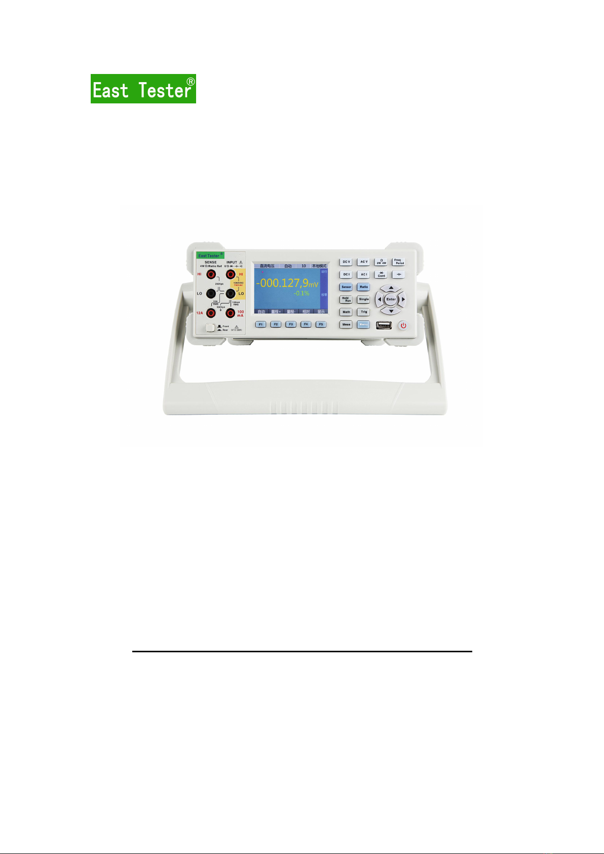
1.2 Front Panel............................................................................................................................ 8
1.3 Rear Panel............................................................................................................................10
1.4 Adjust Handles.....................................................................................................................11
1.5 Start Multimeter...................................................................................................................11
1.6 User Interface...................................................................................................................... 12
1.7 Measurement Wiring........................................................................................................... 13
2. Basic Operations of Front Panel................................................................................................... 15
2.1 Conduct Basic Measurement...............................................................................................15
2.1.1 DC voltage measurement......................................................................................... 15
2.1.2 DC voltage ratio measurement.................................................................................16
2.1.3 AC voltage measurement......................................................................................... 17
2.1.4 DC current measurement......................................................................................... 18
2.1.5 AC current measurement..........................................................................................19
2.1.6 Resistance measurement.......................................................................................... 20
2.1.7 Frequency/Period measurement...............................................................................21
2.1.8 Capacitance measurement........................................................................................22
2.1.9 Continuity measurement.......................................................................................... 23
2.1.10 Diode measurement................................................................................................23
2.2 Usage of Sensor...................................................................................................................24
2.2.1 Thermal resistance sensor........................................................................................ 24
3. Characteristic and Function...........................................................................................................24
3.1 Measurement Configuration................................................................................................24
3.1.1 AC signal filter......................................................................................................... 24
3.1.2 Continuity threshold resistance................................................................................25
3.1.3 DC input resistance.................................................................................................. 25
3.1.4 Resolution.................................................................................................................26
3.1.5 Integral time............................................................................................................. 27
3.1.6 Switch between front/rear input terminals...............................................................27
3.1.7 Auto zero calibration................................................................................................ 27
3.1.8 Select measurement range (measurement shift)...................................................... 28
3.2 Math Operation....................................................................................................................28
3.2.1 Relative (zero) operation..........................................................................................29
3.2.2 dBm value measurement.......................................................................................... 30
3.2.3 dB value measurement............................................................................................. 30
3.2.4 Limit test.................................................................................................................. 31
3.3 Trigger................................................................................................................................. 32
3.3.2 Reading holding....................................................................................................... 33
3.3.3 Trigger parameter setting......................................................................................... 34
3.3.4 Trigger output...........................................................................................................34

7
3.4 Data Record.........................................................................................................................35
3.5 Relevant System Operations............................................................................................... 35
3.5.1 System setting.......................................................................................................... 35
3.5.2 Command set............................................................................................................36
3.5.3 Topic......................................................................................................................... 36
3.5.4 Self-test.....................................................................................................................36
3.5.5 Calibration................................................................................................................37
3.5.6 System information inquiry and system updating................................................... 37
4. Conduct Remote Control...............................................................................................................37
4.1 GPIB Interface Configuration (Only Supported By ET1260B)......................................... 37
4.2 RS232 Interface Configuration........................................................................................... 38
4.3 USB Interface Configuration.............................................................................................. 38
4.4 LAN Interface Configuration..............................................................................................38
5. Measurement Guide...................................................................................................................... 39
5.1 DC Measurement Considerations....................................................................................... 39
5.1.1 Thermoelectromotive force error............................................................................. 39
5.1.2 DCV load error.................................................................................................................39
5.1.3 DCI load error.......................................................................................................... 40
5.1.4 Noise control............................................................................................................ 40
5.1.5 Resistance measurement considerations..................................................................42
5.2 AC Measurement Considerations........................................................................................42
5.2.1 True virtual value AC measurement........................................................................ 42
5.2.2 Crest factor error (non-sine wave input)..................................................................43
5.2.3 ACV load error......................................................................................................... 44
6. Indicators....................................................................................................................................... 44
6.1 DC Characteristics...............................................................................................................45
6.1.1 Basic characteristics................................................................................................. 45
6.2 Uncertainty Indicators.........................................................................................................47
6.2.1 Additional error........................................................................................................ 48
6.3 AC Characteristics...............................................................................................................48
6.3.1 Basic characteristics................................................................................................. 48
6.3.2 Uncertainty indicators.............................................................................................. 49
6.3.3 Additional error........................................................................................................ 50
6.4 Frequency and Period Characteristics.................................................................................50
6.4.1 Uncertainty indicators.............................................................................................. 50
6.4.2 Low-frequency additional error............................................................................... 51
6.5 Capacitance......................................................................................................................... 51
6.6 Temperature.........................................................................................................................51

Users manual ET1260B and ET1260A 6 1/2 Digit Multimeter
8
1. Quick Start
1.1 Inspect Product Accessories
Confirm that multimeter is attached with the following subjects, among which the optional
accessories can be attached to products only after purchasing. If any subject is missed, please
contact the closest sale office.
Standard equipped accessories:
One set of hard-spot testing line and a
2mm probe
One piece of double-end three-core
power line
One pair of alligator clips
Two pieces of backup power fuses
ET32 User manual
Optional equipped accessories:
GPIB cable
Cabinet-installing suite
PT100 temperature probe
RS232 serial port line
USB data line
1.2 Front Panel
This 6 1/2 digit multimeter provides a 480*320 TFT display, and the equipped display can
indicate current working status, F1-F5 software define area, measured value, etc.
No.
Introduction
1
HI and LO sense input terminals. Use 4-wire resistance voltage to measure the input, or
refer to ratio measurement for voltage input.
2
HI and LO main input terminal, all functions exclusive of current)
3
480×320 TFT LCD
4
Function keys of digit multimeter. Select functions of digit multimeter, such as DC voltage,
AC voltage, DC current, AC current, resistance, continuity, diode test, frequency, period,
capacitance, ratio and sensor.
5
Direction and enter key can set measurement range and measurement rate in normal
measurement interface and can be used in menu selection and numeric value setting in
menu.
6
Soft power switch.
7
USB HOST interface is used for procedure updating and data storage.
8
F1-F5 softkeys. Softkeys are used to select different menu options in digit multimeter menu.

Users manual ET1260B and ET1260A 6 1/2 Digit Multimeter
9
Each softkey function is indicated by the label at screen bottom, and softkeys which are not
indicated by labels on the screen are invalid.
9
100mA and 12A input connection ends are used in AC and DC current measurement
10
Front/rear switch
Keys are classified into three main categories, that is, function key, setting key and redefine key,
among which function key is used to quickly select needed measurement function, setting key to
set system and function parameters, and redefine key to redefine by application program
according to changes of measurement functions.
Function key includes all the basic measurement function keys of DC voltage, DC current, AC
voltage, AC current, resistance 2-wire, resistance 4-wire, frequency, period, on-off, diode, sensor,
capacitance and ratio, among which resistance 2-wire and resistance 4-wire share one key,
frequency and period share one, and on-off and diode share one.
Setting key is to set parameters of current measurement function or system. Frequently-used
settings solely using one key is placed on the panel for quick setting; those non-frequently-used
settings are placed in general setting key and operated through menu. The frequently-used ones
include math function, trigger setting, holding, operating, single trigger, measurement setting,
etc.
Softkey includes 5 redefine keys to redefine by application program as required under different
functions.
: Select DC voltage measurement.
: Select AC voltage measurement.
: Select DC current measurement.
: Select AC current measurement.
: Select 2-wire or 4-wire resistance measurement.
: Select frequency or period measurement.
: Select capacitance measurement.
: Select continuity measurement or diode measurement.
: Select sensor measurement.
: Select ratio measurement.
: Reading holding.
: Single trigger.

Users manual ET1260B and ET1260A 6 1/2 Digit Multimeter
10
: Enter math function configuration.
: Enter trigger function configuration.
: Enter parameter configuration of current measurement function.
: Relative system operations include storage, interface, command set, display, system
information, etc.
: Redefine function.
1.3 Rear Panel
No.
Introduction
1
Power outlet.
2
Power fuses
3
Power switch
4
Voltage selector
5
VCM output (voltmeter completes measurement output)
6
External output
7
Current input fuse
8
HI and LO main input terminal
9
HI and LO sensor input terminal
10
Current input terminal
11
USB Device interface
12
LAN interface
13
RS232 interface
14
GPIB interface
Remark: Only terminals of No. 8, 9, 10 and 14 are used on “ET1260B”.

Users manual ET1260B and ET1260A 6 1/2 Digit Multimeter
11
1.4 Adjust Handles
To adjust handles of digit multimeter, please hold the handles on both sides of the meter, and
then rotate the handles to the needed positions. Operating method is as shown in the following
figure
Handles adjusting method
Position during working Position during carriage
1.5 Start Multimeter
1. Connect to AC power
1) Power supply of multimeter may select 110V or 220V, and you may adjust power voltage
selector installed on multimeter rear panel according to your power supply voltage.
2) Connect the multimeter to AC power with power line supplied by accessories.
2. Start multimeter
Turn on the power switch under power outlet.
3. If the instrument is not normally started, please check according to the following steps:
1) Check whether power line is well connected.
2) Check whether the power switch of rear panel is turned on.
3) If the instrument still can not be started after check, please check whether the power fuse is
blown out, if necessary, replace fuses.
4) If the instrument still can not be started after check, please contact relevant departments.

Users manual ET1260B and ET1260A 6 1/2 Digit Multimeter
12
1.6 User Interface
User interface has three kinds of display modes, and can switch among different modes by
pressing the softkey of Display ( ).
Default user display interface:
Description: The figure displays the interface during AC voltage measurement, with major
display being voltage measurement value, and auxiliary display frequency measurement value.
Statistic data display interface:
Statistic Data Display
Description: Under this display mode, besides current measurement values, the interface displays
some statistic data, such as maximum value, minimum value, average value and standard
deviation. At the bottom of the screen is the histogram composed of measurement data, showing
data distribution.

Users manual ET1260B and ET1260A 6 1/2 Digit Multimeter
13
History curve display interface:
History curve display
Description: Under this display mode, the upper part of the screen displays current measurement
values, and the lower part displays tendency chart of the recorded data, wherein the abscissa axis
represents number of measurement points, the first record value is 0 and increases by 1 every
time gain a new measurement value; ordinate axis represents measurement value.
1.7 Measurement Wiring
Note: The main input LO terminal and sense LO terminal of DC voltage ratio measurement
function have to share common reference points, and their voltage difference can not exceed
±2V.
Press to select AC voltage measurement function
Press to select DC voltage
measurement function.
Press to select DC voltage ratio
measurement function
AC voltage

Users manual ET1260B and ET1260A 6 1/2 Digit Multimeter
14
Note: 12A and 100mA input terminals are not allowed to be connected to the current
measurement loops at the same time.
looplooploops at the same time.
Note: 12A and 100mA input terminals are not allowed to be connected to the current
measurement loops at the same time.
Press to select DC current
measurement function
1A-12A measurement is as shown in the
following figure
Press to select AC current
measurement function
100mA-12A measurement is as shown in
the following figure:
Press to select 2-wire resistance
measurement function
Press to select 4-wire resistance
measurement function

Users manual ET1260B and ET1260A 6 1/2 Digit Multimeter
15
Press to select capacitance measurement function.
2. Basic Operations of Front Panel
2.1 Conduct Basic Measurement
2.1.1 DC voltage measurement
Basic information
Measurement range: 100mV, 1V, 10V, 100V and 1000V
Maximum resolution: 100nV.
Operation description:
Press to select frequency
measurement function
Press to select period measurement
function
Press to select continuity
measurement function
Press to select diode test
measurement function

Users manual ET1260B and ET1260A 6 1/2 Digit Multimeter
16
1) Press to select DC voltage measurement function, and automatically enter DC
voltage measurement function every time when the machine is started.
Description: Major display value refers to measured voltage value, and auxiliary displayed value
refers to the ratio between current measurement value and full measurement range.
2) Connect test lines as indicated in chapter “1.4 Measurement wiring”.
3) Select measurement range as required, and may select automatic measurement, or press the
softkeys of Measurement range+ ( ) and Measurement range- ( ) to select fixed
measurement range, which have same effect as keys of and .
4) Press the softkey of Relative ( ) to record the current value, after which display the
difference between actual measurement value and current recorded value.
5) Press the softkey of Display ( ) to switch modes, and refer to the chapter of User
interface for details.
6) If necessary, press to configure the following measurement parameters: integral time,
input impedance and zero calibration method, and refer to the chapter of Measurement
configuration for details.
7) If necessary, press to configure math operation function (limits, dBm, dB and relative),
and refer to description in the chapter of Math operation for details.
2.1.2 DC voltage ratio measurement
Basic Information
Ratio measurement refers to that measure input voltages to main input terminal and sense
terminal with multimeter, and work out the ratio.
Voltage ratio= Voltage value of main input terminal/Voltage value of sense terminal.
Main input LO terminal and sense LO terminal have to share common reference points, and
their voltage difference can not exceed ±2V.
Ration measurement is automatic measurement range measurement, and automatic zero
calibration is started. Main input terminal can measure up to 1000V voltage at most, and
sense terminal to 12V voltage at most.
Operation description

Users manual ET1260B and ET1260A 6 1/2 Digit Multimeter
17
1) Press to select DC voltage ratio measurement function.
Description: Major display represents the voltage ratio value between main input terminal and
sense terminal, the lower part (IN) represents voltage value measured at main input terminal, and
(REF) represents reference voltage value measured at sense terminal.
2) Connect test lines as indicated in the chapter of 1.4 Measurement wiring.
3) Press and to select different integral times, and refer to the chapter of Measurement
configuration for details
2.1.3 AC voltage measurement
Basic information
Measurement range: 100mV, 1V, 10V, 100V and 750V.
AC technology: true virtual value measurement and AC coupling method.
Maximum resolution: 100nV.
Operation description
1) Press to select AC voltage measurement function.
Description: Major displayed value refers to measurement voltage value, and auxiliary displayed
value refers to frequency measurement value of the current input signal.
2) Connect test lines as indicated in the chapter of 1.4 Measurement wiring.
3) Select measurement range as required, and may select automatic measurement, or press the
softkeys of Measurement range+ ( ) and Measurement range- ( ) to select fixed

Users manual ET1260B and ET1260A 6 1/2 Digit Multimeter
18
measurement range, which have same effect as keys of and .
4) Press the softkey of Relative ( ) to record the current value, after which display the
difference between actual measurement value and current recorded value.
5) Press the softkey of Display ( ) to switch modes, and refer to the chapter of “Users
interface” for details.
6) If necessary, press to configure the following measurement parameters: AC filter, and
refer to the chapter of Measurement configuration for details.
7) If necessary, press to configure math operation function (limits, dBm, dB and relative),
and refer to description in the chapter of Math operation for details.
2.1.4 DC current measurement
Basic information
Current measurement is classified into low current measurement and high current
measurement, with different wiring methods.
Low current measurement range: 10uA, 100uA, 1mA, 10mA and 100mA
High current measurement range: 1A and 12A.
Maximum resolution: 10pA.
Operation description
1) Press to select DC current measurement function.
Description: Major displayed value refers to measurement current value, and auxiliary displayed
value refers to the ratio between current measurement value and full measurement range.
2) Connect test lines as indicated in the chapter of 1.4 Measurement wiring.
3) Select measurement range as required, and may select automatic measurement, press the
softkey of to select low current measurement, press the softkey of to select high current
measurement, and press keys of and to switch measurement range.
4) Press the softkey of Relative ( ) to record the current value, after which display the
difference between actual measurement value and current recorded value.
5) Press the softkey of Display ( ) to switch modes, and refer to the chapter of User

Users manual ET1260B and ET1260A 6 1/2 Digit Multimeter
19
interface for details.
6) If necessary, press to configure the following measurement parameters: integral time,
input impedance and zero calibration method, and refer to the chapter of Measurement
configuration for details.
7) If necessary, press to configure math operation function (limits, dBm, dB and relative),
and refer to description in the chapter of Math operation for details.
2.1.5 AC current measurement
Basic information
Current measurement is classified into low current measurement and high current
measurement, with different wiring methods.
Low current measurement range: 100uA, 1mA, 10mA and 100mA
High current measurement range: 1A and 12A.
Maximum resolution: 100pA.
Operation description
1) Press to select AC current measurement function.
Description: Major displayed value refers to measurement current value, and auxiliary displayed
value refers to frequency measurement value of the current input signal.
2) Connect test lines as indicated in the chapter of 1.4 Measurement wiring.
3) Select measurement range as required, and may select automatic measurement, press the
softkey of to select low current measurement, press the softkey of to select high current
measurement, and press keys of and to switch measurement range.
4) Press the softkey of Relative ( ) to record the current value, after which display the
difference between actual measurement value and current recorded value.
5) Press the softkey of Display ( ) to switch modes, and refer to the chapter of Users
interface for details.
6) If necessary, press to configure the following measurement parameters: AC filter and
refer to the chapter of Measurement configuration for details.
7) If necessary, press to configure math operation function (limits and relative), and refer
to description in the chapter of Math operation for details.

Users manual ET1260B and ET1260A 6 1/2 Digit Multimeter
20
2.1.6 Resistance measurement
Basic information
10Ω, 100Ω, 1kΩ, 10kΩ, 100kΩ, 1MΩ, 10MΩ, 100MΩ and 1GΩ.
Maximum resolution: 10uΩ.
Operation description
1) Press to select 2-wire resistance measurement or 4-wire resistance measurement
function.
Description: Major displayed value refers to measurement voltage value, and auxiliary displayed
value refers to the ratio between the current measurement value and full measurement range.
2) Connect test lines as indicated in the chapter of 1.4 Measurement wiring.
3) Select measurement range as required, and may select automatic measurement, or press the
softkeys of Measurement range+ ( ) and Measurement range- ( ) to select fixed
measurement range, which have same effect as keys of and .
4) Press the softkey of Relative ( ) to record the current value, after which display the
difference between actual measurement value and current recorded value.
5) Press the softkey of Display ( ) to switch modes, and refer to the chapter of User
interface for details.
6) If necessary, press to configure the following measurement parameters: integral time
and zero calibration and refer to the chapter of Measurement configuration for details. Start
automatic zero calibration during 4-wire resistance measurement.
Table of contents
Other East Tester Multimeter manuals