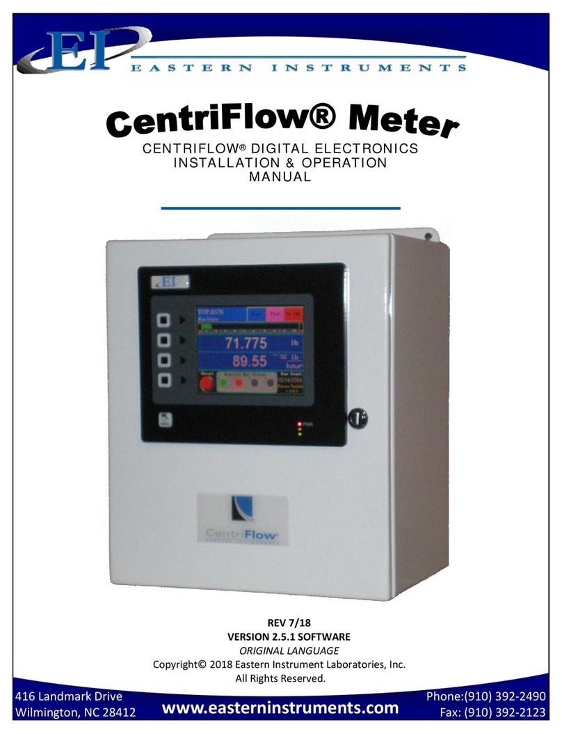
EASTERN INSTRUMENTS CENTRIFEEDER ELECTRONICS User manual

Phone:(910)392‐2490
Fax:(910)392‐2123
416LandmarkDrive
Wilmington,NC28412www.easterninstruments.com
CENTRIFEEDER ELECTRONICS
FOR USE WITH CENTRIFEEDER with
Integrated Vibratory Control
REV4/16ADDENDUM
VERSION8.5.0SOFTWARE
Copyright©2011EasternInstrumentLaboratories,Inc.
AllRightsReserved.

2
Phone:(910)392‐2490
Fax:(910)392‐2123
416LandmarkDrive
Wilmington,NC28412www.easterninstruments.com
TABLEOFCONTENTS
SAFETY
SafeOperation.................................................................................................................3
WarningsandCautions...................................................................................................3
SafetyPlacards................................................................................................................4
1.InstallationGuidelines.......................................................................................................5
Requirements................................................................................................................5
TroubleAreas................................................................................................................5
RemoteElectronicsEnclosureDrawing........................................................................6
2.IdentifyingYourComponents.........................................................................................7
RemoteElectronics.......................................................................................................7
CentriFeederVIB...........................................................................................................8
ACloserLookAtYourHMI............................................................................................9
3.BasicWiring...................................................................................................................10
GroundingtheCentriFeederMeterModule..............................................................11
WiringtheRemoteElectronicsCableattheMeterModule......................................12
WiringtheCustomerConnections..............................................................................13
CustomerConnectionsOutputs..................................................................................14
WiringtheRemoteElectronicsCable.........................................................................16
WiringtheVibratoryDrive..........................................................................................17
ConnectingPower.......................................................................................................18
4.Procedures.....................................................................................................................19
PoweringOn................................................................................................................19
VibratoryScaling.........................................................................................................21
AdvancedControlSettings..........................................................................................22
StaticCalibration.........................................................................................................24
SiteCalibration............................................................................................................26
SettingtheAlarm‐Rate..............................................................................................31
SettingtheAlarm‐Totalization..................................................................................31
SetupofRemoteReset&ZeroCapability..................................................................33
UsingtheCompactFlash.............................................................................................34
RemoteEthernetAccess.............................................................................................36
RemoteView...............................................................................................................37
ViewLogs....................................................................................................................37
5.ChangingtheIPAddress...............................................................................................40
ExampleofEstablishingCommunicationtoPLC:ControlLogixUnit..........................42
TagMapping...............................................................................................................42
SecurityFeatures........................................................................................................45
6.Certificates.....................................................................................................................47

3
Phone:(910)392‐2490
Fax:(910)392‐2123
416LandmarkDrive
Wilmington,NC28412www.easterninstruments.com
PLEASEREADBEFOREOPERATINGTHECENTRIFLOWMETER
OnlyauthorizedpersonnelshouldoperatetheCentriFlowMeter.Untrainedpersonnel
presentahazardtothemselvesandthemeterandimproperoperationwillvoidthewar‐
ranty.
Checkfordamagedpartsbeforeoperatingthemeter.Anydamagedpartshouldbeprop‐
erlyrepairedorreplacedbytrainedpersonnel.Donotoperatethemeterifanycompo‐
nentdoesnotappeartobefunctioningcorrectly.ContactEasternInstrumentsforassis‐
tanceorforrepaircomponents.
UsetheappropriatePersonalProtectionEquipmentasrequiredforoperatingthemeter
withinitsinstallationlocation.
ThevarioussurfacesoftheCentriFlowMetermodulemayhavesharpedgesandhavethe
potentialtocauseinjury.Usetheproperprotectionforyourhandswhenservicingor
maintainingyourCentriFlowMeter
Theelectricalpanel(digitalelectronics)shouldbeclosedandthesafetylatchengagedatall
timesexceptduringinstallationorservice.Atthosetimes,onlyauthorizedpersonnel
shouldhaveaccesstotheelectronicspanel.Whenpowerisactivated,ACvoltagemaybe
presentthroughoutthepanel.Thereforeextremecautionisrequired.
DONOTmodifyoralterthisequipmentinanyway.Ifmodificationsarenecessary,all
suchrequestsmustbehandledbyEasternInstruments.Anymodificationoralteration
ofanyEasternInstrumentsequipmentcouldleadtopersonalinjuryand/ormechanical
damageandwillvoidthewarranty.
OncepowerhasbeensuppliedtotheCentriFlowMeter,itisalways
onandproductmayrunthroughitatanytime.
Avoidenteringorplacingbodypartswithinthemeter’senclosure.
Donotoperatewithoutpropertraining
AlwayswearproperPPE
NEVERservicethemeterwhilepowerisconnected.
SAFETY
SAFETY
WARNINGSANDCAUTIONS
WARNINGSANDCAUTIONS
SAFEOPERATION
SAFEOPERATION

4
Phone:(910)392‐2490
Fax:(910)392‐2123
416LandmarkDrive
Wilmington,NC28412www.easterninstruments.com
SOMEORALLOFTHESEWARNINGSMAYBEONYOURMETER.BEAWAREOFTHEPOSSIBLE
DANGERSPRESENT.
SAFETYPLACARDS
SAFETYPLACARDS
ELECTRICALSERVICE
Electricalshockorelectrocutionispossiblewhenservicingthe
electronicsofanyEasternInstrumentsequipment.Besureto
disconnectpowerbeforeconductinganyrepairsontheelec‐
tronics.
PRODUCTFLOW
TheControlValvefortheCentriFeederisusedonlyasacontrol
valveanddoesnotactasanisolationvalve.Asecondaryisola‐
tionvalveisrecommendedtobeinstalledbeforetheCen‐
triFeeder’scontrolvalveinordertoisolatetheCentriFeeder
fromflowduringmaintenanceorrepairs.
PINCHPOINTS
ThecontrolvalveoftheCentriFeedercancauseseriousinjury
oramputation.Keephandsclearofthecontrolvalveatall
times.
LIVEELECTRICITY
Liveelectricalwiresmaybepresent.Pleasenotethatcoming
intocontactwiththelivewires(ACPower)couldcauseelectri‐
calshockorelectrocution.
MOVINGBLADE
WILLCAUSE
SERIOUSINJURYOR
AMPUTATION
Thisisacontrolvalve,not
anisolatingvalve.An
isolatingvalveshouldbe
installedBEFOREthis
controlvalve.

5
Phone:(910)392‐2490
Fax:(910)392‐2123
416LandmarkDrive
Wilmington,NC28412www.easterninstruments.com
INSTALLATIONREQUIREMENTS
Themeteristobeusedinalocationwheretheproductcanbedroppedfromafixed
heightsuchasaconveyer,oranytypeoffeedsystem,whichwillgiveareasonably
constantinitialverticalvelocity.Thedesignofthemeterrequirestheproducttocontact
theTangentialPlateandhavesomeverticaldrop.
Themetershouldbeinstalledsothatitislevelintwoplanes.UsetheBubbleLevelontop
oftheSealToptohelp.
Themetershouldbemountedusingthemountholesonly.Themountingmethodshould
minimizevibrationandanymovement.Mountingshouldnotbedoneusingtheflange(s).
Thedischargechutethattheproductstreamemptiesintoaftertravelingthroughthe
metermustbefreeflowing,meaningthatitdoesnotallowproducttobuildupand
consequentlycontactthePanofthemeter.
TheElectronicsEnclosureandvalveshouldbewiredusingonlythefactorycable.Thereis
astandard10’cablepackagethatincludestheRemoteElectronicsCable,thevalvePower
Cable,andtheValvePositionSensorCablesuppliedwiththeCentriFeeder™Meter.The
cablesshouldbecuttotheexactlengthrequired.Donotcoilthecables.
ItisrequiredthattheRemoteElectronicsCableberunthroughitsowngroundedmetallic
conduitconnectedonthesideofthemoduleandthebottomoftheElectronicsEnclosure.
ThisCableMUSTbeinaseparateconduitthanthatoftheACPoweror24VdcPowersup‐
pliedtotheElectronicsEnclosure.Thevalvepowerandpositionsensorsignalcablecanbe
togetherintheirowngroundedmetallicconduit.
INSTALLATIONTROUBLEAREAS
TheCentriFeeder™Meter’s4‐20mAsignalisself‐poweredanddoesnotrequireany
additionalvoltage.
DONOTRUN480V,240V,OR120VANDSIGNALLINESINTHESAMECONDUIT.Thepower
andsignallinesshouldbeseparatefromeachotherandfromallotherdevices.Running
anyotherpowerorsignallinesinthesameconduitcouldaffecttheperformanceofyour
meter.Isolatebothpowerandsignallinesfromeachotheratalltimes.
TheCentriFeeder™Meterisbalancedataspecificangleandshouldnotbesubjectto
vibrationormovement.Themassofthemountshouldbeatleast2timesthemassofthe
meter.
TheSealTopshouldbeonthemeteratalltimesthatyouarenotworkinginsidethemeter.
Thisistokeepallforeignmaterialsoutofthemeterthatcouldobstructitsmovementor
impairitsfunctionality.
INSTALLATION
INSTALLATION

6
Phone:(910)392‐2490
Fax:(910)392‐2123
416LandmarkDrive
Wilmington,NC28412www.easterninstruments.com
ElectronicsEnclosure
DimensionalDrawing

7
Phone:(910)392‐2490
Fax:(910)392‐2123
416LandmarkDrive
Wilmington,NC28412www.easterninstruments.com
Phone:(910)392‐2490
Fax:(910)392‐2123
416LandmarkDrive
Wilmington,NC28412www.easterninstruments.com
TheDigitalElectronicsEnclosurecontainstheHMI,theDigitalCentriFlow®Electronics(DCE),
PowerSupply,AlarmRelay,PowerConnectionswithKnifeDisconnects,andtheCustomer
Connections.
HMI
OPERATINGTOOL
POWERSUPPLY
BACKPLANE
NEMA4CARBON
STEELENCLOSURE
(OPTIONALSS)
WIREWAYS
CUSTOMERCONNECTION
LABEL
GROUNDCONNECTION
ACONLYAREA
POWERCONNECTIONS
WITHKNIFEDISCONNECTS
(MayBeCircuitBreakers)
ENCLOSUREDOOR
DCEWITH
LCDDISPLAY
CUSTOMER
CONNECTIONS
WIREWAY
IdentifyingYourComponents:
RemoteElectronics

8
Phone:(910)392‐2490
Fax:(910)392‐2123
416LandmarkDrive
Wilmington,NC28412www.easterninstruments.com
Phone:(910)392‐2490
Fax:(910)392‐2123
416LandmarkDrive
Wilmington,NC28412www.easterninstruments.com
IdentifyingYourComponents:
CentriFeederVIB
HOPPER
VIBRATORYCONVEYOR
METERMODULE
VIBRATORYFEEDER
MOUNTPLATE

9
Phone:(910)392‐2490
Fax:(910)392‐2123
416LandmarkDrive
Wilmington,NC28412www.easterninstruments.com
Phone:(910)392‐2490
Fax:(910)392‐2123
416LandmarkDrive
Wilmington,NC28412www.easterninstruments.com
ThemaincomponentsofyourHMITouchScreenwillbetheTouchScreenitself,theLEDDis‐
play,theMenuSoft‐Key,andSoft‐Keys1thru4.BypressingtheMenuSoft‐Key,youwillbe
returnedtotheMainMenu,orTOPpage.TheLEDDisplaywillgiveyouinformationonyour
process,thestatusofyourCompactFlashCardandonthestatusofanyalarmsthathavebeen
activated.BelowisadetaileddescriptionoftheLEDDisplay.
LEDDISPLAYCHART
ACloserLookatYourHMI
SOFTKEYS1‐4
MENUSOFTKEY
TOUCHSCREEN
LEDDISPLAY
LED ACTIVITY INDICATION
RED(TOP)
FLASHING Unitisinthebootloader,novalidconfigurationisloaded
STEADY Unitispoweredandrunninganapplication
YELLOW(MIDDLE)
OFF NoCompactFlashispresent
STEADY ValidCompactFlashcardispresent
FLASHINGRAPIDLY CompactFlashcardisbeingchecked
FLICKERING
UnitiswritingtotheCompactFlash,eitherbecauseitis
storingdata,orbecausethePCconnectedviatheUSBport
haslockedthedrive
FLASHINGSLOWLY IncorrectlyformattedCompactFlashcardispresent
GREEN(BOTTOM)
FLASHING Atagisinanalarmstate
STEADY Validconfigurationisloadedandthereisnoalarmpresent

10
Phone:(910)392‐2490
416LandmarkDrivewww.easterninstruments.com
BasicWiring
WiringoftheCentriFeeder®canbebrokendowntothefollowingcategories:
REMOTEELECTRONICS:
GroundingtheCentriFeederModule
WiringtheElectronicsCableattheMeterModule
WiringtheCustomerConnectionsatElectronicsEnclosure
ConnectingPower
ElectricalInformation:
ThefollowingDCEdigitalsignalsarephototransistorout‐
puts:
Frequency,FlowRateProportional(Rate)
TheInternalDCESchematictotherightshowstheRate
Output.However,alldigitaloutputsaredesignedusingthe
samecircuit.
*DigitalOutput1and2sharepowerandground
**DigitalOutput3and4sharepowerandground
*Afullwiringdiagramisprovidedattheendofthemanual.
DigitalOutput Function
DOUT1* (Option)
DOUT2* Alarm
DOUT3** (Option)
DOUT4** (Option)
RATE Frequency,FlowRate
Proportional
COUNT WeightedCount(Option)

11
Phone:(910)392‐2490
Fax:(910)392‐2123
416LandmarkDrive
Wilmington,NC28412www.easterninstruments.com
Phone:(910)392‐2490
Fax:(910)392‐2123
416LandmarkDrive
Wilmington,NC28412www.easterninstruments.com
AseparateEarthGroundWire(14gauge)isrequiredtobeconnectedtothemetermodule.This
groundwireisrequiredforoperatorsafetyandforproperoperation.Thisgroundmustbesup‐
pliedfromthemainplantgroundattheserviceentrance.
PLEASEBESURETOGROUNDTHECENTRIFEEDERMETERMODULETOANEARTHGROUND!
GroundingtheCentriFeederMeterModule

12
Phone:(910)392‐2490
416LandmarkDrivewww.easterninstruments.com
REMOTEELECTRONICSCABLE
TheRemoteElectronicsCableisa9conductorcablewithashieldthatattachestheCentri‐
Flow®MeterModuleofyourCentriFeedertotheElectronicsEnclosure.Itsendsthemeasure‐
mentsignalfromtheTransducerinsidetheModuletotheElectronicsPanelinsidetheElec‐
tronicsEnclosure.Thestandardlengthis10’long,butitshouldbecuttotheexactlength
needed.IfthedistancefromtheCentriFlow®MeterModuletotheElectronicsEnclosureis
morethan10’,acustomlengthcablewhichmaybesuppliedwiththemeter,shouldalsobe
cuttofit.ExcesscableshouldneverbecoiledupandplacedintotheCentriFlow®MeterMod‐
ule.OneendoftheRemoteElectronicsCablewillbeaffixedtothemetermodule,whilethe
otherendwillbecuttolengthandwillbewiredtotheElectronicsEnclosureasdemonstrated
inthe“WiringtheDigitalElectronics”portionofthismanual.
PLEASENOTE:TheElectronicsCableMUSTberunthroughgroundedmetallicconduit.Ifyour
ElectronicsCablehasanAmphenolConnectorononeend,wewouldrecommendleavinga
shortlengthofcableoutoftheconduitnearthemetermoduleandusingacablegland/wire
griptypeofconnectorontheendoftheconduit. TheAmphenolconnectorcanbeexposed
withoutbeinginsidetheconduit.
Amphenol
Connectorfor
VibraWeigh
WIRINGTHEMETERMODULE‐9CONDUCTORCABLE:
AmphenolConnector
CableGland
Connector
MetallicConduit
RemoteElectronicsCable
OneendoftheRemoteElectronicsCablewillbeaffixedwitha10‐pinAmphenolConnector.
ThisendwillbeconnectedtotheMeterModuleCasingasshowninthepicturebelow.The
otherendofthecablewillbecuttolengthandwillbewiredtotheElectronicsEnclosureas
demonstratedinthe“WiringtheDigitalElectronics”portionofthismanual.
PLEASENOTE:VibraWeighAmphenolConnectoris
a3‐pinconnectorwhiletheRemoteElectronics
Cableisa10‐pinAmphenolConnector
WiringTheRemoteElectronicsCableAtTheMeterModule

13
Phone:(910)392‐2490
Fax:(910)392‐2123
416LandmarkDrive
Wilmington,NC28412www.easterninstruments.com
WiringCustomerConnectionsAttheElectronicsEnclosure
*AllConnectionsaremadetotheBottomoftheTerminalBlocks
FrequencyFlowRate(+)
FrequencyFlowRate(OUT)
FrequencyFlowRate(‐)
LocalPower(+)
LocalPower(‐)
AlarmRelay(N.C.OUT)
AlarmRelay(COMOUT)
AlarmRelay(N.O.OUT)
4‐20mALoop(+)
4‐20mALoop(‐)
EARTHGROUND
N.C.‐NormallyClosed
N.O.‐NormallyOpen
RemoteReset/Zero(SwitchInput)
RemoteStart(SwitchInput)
RemoteStop(SwitchInput)
RemoteElectronicsCable(+AuxiliaryInput)
RemoteStart(SwitchInput)
RemoteStop(SwitchInput)
RemoteElectronicsCable(‐Excitation)
RemoteElectronicsCable(+Excitation)
RemoteElectronicsCable(‐Signal)
RemoteElectronicsCable(+Signal)
RemoteElectronicsCable(Temperature)
RemoteElectronicsCable(‐AuxiliaryInput)
EARTHGROUND

14
Phone:(910)392‐2490
Fax:(910)392‐2123
416LandmarkDrive
Wilmington,NC28412www.easterninstruments.com
24VLocalPowerOutput
Foryourconveniencea24VoltLocalPowerOutputhasbeenprovidedthatcanbeusedto
powerthevariousoutputsaslistedabove.InstallaJumperWirefromthepositiveterminalof
theLocalPowerOutputtothepositiveterminalofthedesiredoutputandaJumperWirefrom
thenegativeterminaloftheLocalPowerOutputtothenegativeterminalofthedesiredout‐
putstoprovidepowertotheoutput.
Note:Useoflocalpowerwillresultinalossofisolation.
4‐20mAOutput
AnalogOutput(Sourced)
LoopPowerNOTRequired
MaximumLoadResistance=900ohms
NOTAVAILABLEFORCENTRIFEEDERVIB
TheCentriFlow®MeterElectronicsiscapableofoutputtingananalogsignal.Thissignalisa4‐
20mAinstantaneousisolatedsignal.ThesignaloutputisproportionaltotheElectronicFull
ScaleFlowRate.Forexample,iftheElectronicFullScaleFlowRatewerecalibratedtobe300
lb/min,thenanoutputof12mAwouldcorrespondtoaFlowRateof(12‐4)/(20‐4)x300=150
lb./minor50%oftheElectronicFullScaleFlowRate.Sincethisoutputisdirectlyrelatedto
theElectronicFullScaleFlowRateanychangeinCalibrationtochangetheElectronicFullScale
FlowRatewouldresultinachangeinthesignalsoastoretaintheproportionality.Thus,ifthe
ElectronicFullScaleFlowRatewerechangedfrom300lb./minto500lb./min,thena20mA
outputwouldcorrespondtothe500lb/minflowrate.Connectiontothisoutputsignalwillbe
madeaccordingtotheCUSTOMERCONNECTIONSdiagrambelow.Itisrecommendedthatthe
wiresforthissignalberoutedthroughtheconduithousingthepowerconnection.Itisrecom‐
mendedthatthisanalogoutputbeusedforControlpurposesandnotforTrendingunlessa
signalfilterisused.Pleaseseethefilteringsectionofthismanualformoredetailsonfiltering.
AlarmOutput
RelayOutput
Therelaycanbeusedtotriggeralarmswhichwarntheoperatorthatabatchiscompleteor
thattheflowratehasexceededathreshold.Theoutputisprogrammabletobeassignedfor
rateorcount.Whenassignedtothecount,therelaycanhaveauserselectableontime
(duration)orcanbelatcheduntilreset.
CustomerConnectionsOutputs

15
Phone:(910)392‐2490
Fax:(910)392‐2123
416LandmarkDrive
Wilmington,NC28412www.easterninstruments.com
Frequency,FlowRateProportional(Rate)
DigitalOutput
PowerRequired
TheCentriFlow®MeterElectronicsiscapableofoutputtingaTotalizingPulseOutputsignal.
TheFrequency,FlowRateProportionalsignalisapulsesignalandislabeled“Rate”atthe
CUSTOMERCONNECTIONblock.Thefrequencyofthesignalis0to500pulsespersecond.
TheRate+,suppliedbythecustomercanbebetween12and24Volts.TheRate‐isconnected
totheCommonorPowerSupplyGround.ByconnectingtheRate+andRate‐withcustomer
suppliedpowerandground,theRateOutsignalwillbeisolatedfromtheDigitalElectronics.
AlthoughthepreferredmethodofsupplyingpowertotheRateoutputiscustomersupplied
power,+24Vlocalpowerisalsoavailable.Usingthelocalpower,however,resultsinalossof
isolation.
ThisTotalizingPulseOutputwilloutputaVoltagePulsethatisrelatedtotheElectronicFull
ScaleFlowRate.Forexample,iftheElectronicFullScaleFlowRatewerecalibratedtobe300
lb./min,thenaflowrateof150lb./minwouldcorrespondtoapulseof250,or50%ofElec‐
tronicFullScaleFlowRate.
RemoteReset/Zero
DigitalInput
PushbuttonSwitch
Byinstallingapushbuttonon/offswitchorothermechanicalrelaycontact,theRemoteInput
canbeusedtoremotelyresetyourcount.Inorderforthisoptiontobeutilizedthepushbut‐
tonon/offswitchorothermechanicalrelaycontacts(customersupplied)mustbeinstalled
usingtheconnectionlistedbelow.Pleasenotethattheseinputsareprewiredwithvoltage
andonlyrequirecontactclosurestooperatecorrectly(WiringanSSRtothisinputwillnot
workproperly).

16
Phone:(910)392‐2490
Fax:(910)392‐2123
416LandmarkDrive
Wilmington,NC28412www.easterninstruments.com
Remote Electronics
Cable 4 Conductor Cable 6 Conductor Cable Landing Terminal
Shield Shield Shield Ground Terminal
- Signal Red Wire Red Wire 70
- Excitation Black Wire Black Wire 71
+ Excitation Green Wire Green Wire 72
+ Signal White Wire White Wire 73
Temperature N/A Blue Wire 75
+ Auxiliary Input N/A N/A 76
- Auxiliary Input N/A N/A 77
Ground Green or
Green/Yellow Wire
(Separate Wire)
Green or
Green/Yellow Wire
(Separate Wire) Ground Terminal
9 Conductor Cable
N/A
Red Wire
Black Wire
Green/Black Wire
White Wire
Blue Wire
Red/Black Wire
White/Black Wire
Green Wire
Temperature N/A Gold Wire Gold Wire 74
WiringtheRemoteElectronicsCable
WhenwiringtheRemoteElectronicsCabletoyourDigitalElectronicsEnclosure,pleasematch
theCustomerConnectionsterminalsinsideyourDigitalElectronicstothepicturebelow.If
theyaredifferentpleasecontactEIforfurtherinstructions.Thetablebelowshowsthecorrect
wirecolorandterminalforeachtypeofRemoteElectronicsCableavailable.Matchyourcable
tothecolumninthetablebelowandensurethattheappropriatewiresarelandedtotheap‐
propriateterminals.

17
Phone:(910)392‐2490
Fax:(910)392‐2123
416LandmarkDrive
Wilmington,NC28412www.easterninstruments.com
*AllConnectionsaremadetotheBottomoftheTerminalBlocks
VibratoryDrive
YoumustwiretheVibratoryConveyortotheElectronicsControllerbyattachingthewirefrom
theVibratoryConveyor(provided)totheCustomerConnectionsasshownbelow.
VibratoryPower(N)‐ #3CUSTOMERCONNECTIONS
VibratoryPower(L)‐ #4CUSTOMERCONNECTIONS
Ground ‐GROUND

18
Phone:(910)392‐2490
Fax:(910)392‐2123
416LandmarkDrive
Wilmington,NC28412www.easterninstruments.com
*AllConnectionsaremadetotheBottomoftheTerminalBlocks
Power
TheDigitalElectronicsPackageincludesaPowerSupplytoconvertthecustomerprovidedVAC
powerto24Vdc.Pleaseseethediagrambelowforwiringconnections.
WARNING:TURNPOWEROFFATSUPPLYCIRCUITBREAKERBEFOREWIRINGTHEPOWERTO
YOURDIGITALELECTRONICSPACKAGE!
VACONLYcanbeconnectedtothePowerterminalsillustratedbelow.TheVACpoweristhen
convertedto24VdcthroughthefactorywiredPowerSupplytosupply24Vdcpowertothe
electronics.
WiretheVACNeutralandVACLineconnectionstotheterminalblocksusingthetoolprovided.
Thewiringconnectionsareasfollows:
ACGround‐ G(Green)
VACNeutral‐ N(White/Yellow)
VACLine‐ L(Black)
Circuit
Breakers
InputVoltage 115VAC
InputCurrent 5A
InputFrequency47‐63Hz

19
Phone:(910)392‐2490
Fax:(910)392‐2123
416LandmarkDrive
Wilmington,NC28412www.easterninstruments.com
PoweringOn
CircuitBreakers
Topoweronyourdigitalelectronics,opentheDigitalElectronicsEnclosureanddepressthe
breakerpushbuttonslocatedontheVACPowerwiringconnectionsasshownbelow.
ClosetheDigitalElectronicsEnclosure.TheHMIshouldnowbecomingon.Uponstartup,the
HMIwilldisplaytheMainMenuScreen,alsocalledTOP,asshownbelow.
PROCEDURES
PROCEDURES

20
Phone:(910)392‐2490
Fax:(910)392‐2123
416LandmarkDrive
Wilmington,NC28412www.easterninstruments.com
TOP.RUN
TOP.RUNisthemaindisplaymode.AccessthisscreenbypressingtheRUNButtonfromthe
TOPscreen.ThecustomercanchoosebetweenAutomaticModeandManualModefromthis
screenaswellasviewdatainrealtime.
TheRedandGreenBarontheLowerRightlabeledSPandPV:SPstandsforSetPointand
representsthechosenvalueyouwouldliketheprocesstorunat.Itisrepresentedasaper‐
centageofyourEFSvalue,orElectronicFullScale.PVindicatesyourProcessValue,orwhat
theprocessisactuallyrunningat.
PV/SPinEngineeringUnits:TheSPandPVvaluesarealsorepresentedinEngineeringUnitsin
thesquareabovetheRun/Stopbuttononthelowerleftsideofthescreen.
Thediagramofthevalve/meter:Agraphicalrepresentationofthevalveandmeterareseen
onthecenterrightofthescreenandinformationrelatingtothevalvecanbeviewedhere.An
Open/Closedindicatorisabovethevalvegraphicwhilethepositionofthevalveisindicatedin
thewhiteblockundertheword“position”onthevalvegraphic.Thevalueisshownasafrac‐
tionof100%open.TheVFSValue,orVirtualFlowStopValueisalsoindicatedasapercentage
of100%open.PleaseseethemanualformoreinformationontheVirtualFlowStop.Near
themeterrepresentationisanalarmindicatorshowingwhetherthealarmhastriggeredor
not.
Total/RateIndicator:InthetopleftcornerundertheAutoandManButtonsarethenumeri‐
calvaluesofthecalculatedTotalandRatevaluesforyourprocessaswellastheunitsofthese
values.
RESET
BUTTON
MANUALBUTTON
MANUALOUTPUT
BUTTON
R‐STOPINDICATOR
Table of contents
Other EASTERN INSTRUMENTS Measuring Instrument manuals
Popular Measuring Instrument manuals by other brands

Agilent Technologies
Agilent Technologies 42941A Operation and service manual

Hanna Instruments
Hanna Instruments HI 983302 instruction manual

OWL
OWL PON-2M Operation guide

PCB Piezotronics
PCB Piezotronics EX357E92 operating guide

Umarex
Umarex MoistureMaster Compact Plus manual

PASCO
PASCO OS-8525A instruction sheet