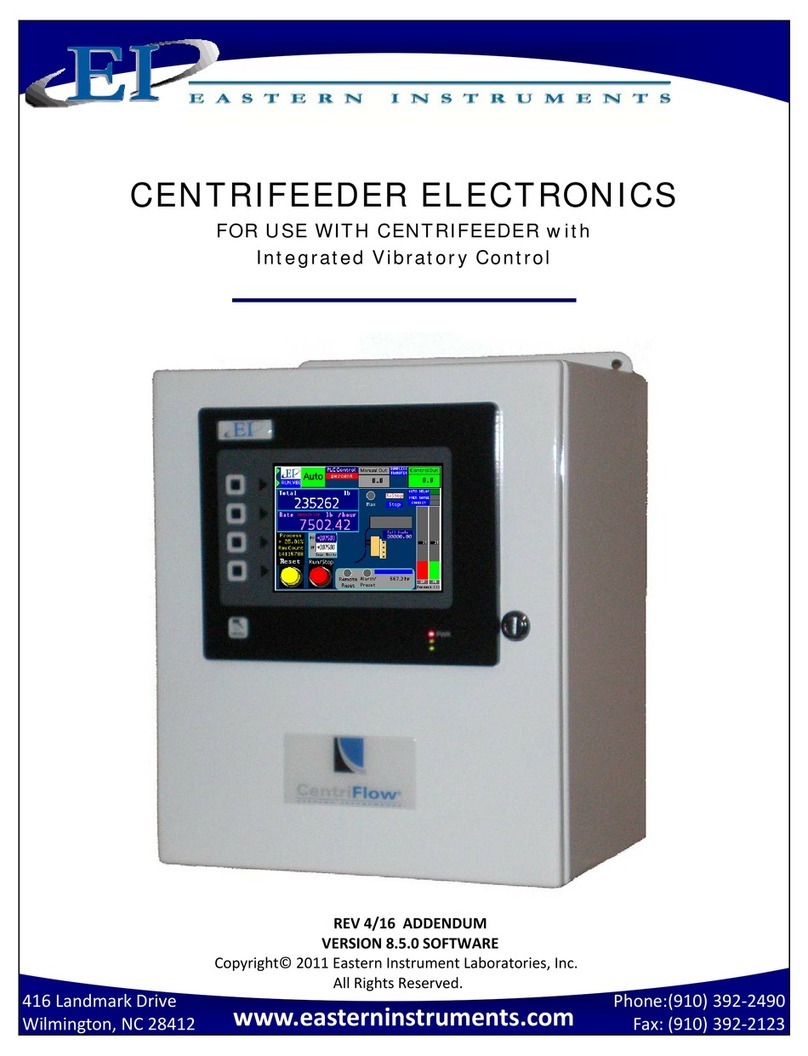
EASTERN INSTRUMENTS CentriFlow User manual

Phone:(910) 392‐2490
Fax: (910) 392‐2123
416 Landmark Drive
Wilmington, NC 28412 www.easterninstruments.com
CENTRIFLOW®DIGITAL ELECTRONICS
INSTALLATION & OPERATION
MANUAL
REV 7/18
VERSION 2.5.1 SOFTWARE
ORIGINAL LANGUAGE
Copyright© 2018 Eastern Instrument Laboratories, Inc.
All Rights Reserved.

2
Phone:(910) 392‐2490
Fax: (910) 392‐2123
416 Landmark Drive
Wilmington, NC 28412 www.easterninstruments.com
TABLE OF CONTENTS
SAFETY
Safe Operaon ................................................................................................................. 4
Warnings and Cauons ................................................................................................... 4
Safety Placards ................................................................................................................ 5
INSTALLATION
1. Installaon Guidelines .................................................................................................... 6
Requirements ................................................................................................................ 6
Trouble Areas ................................................................................................................ 6
Electronics Enclosure Drawing ...................................................................................... 7
OPERATION
4. Idenfying Your Components ......................................................................................... 8
5. A Closer Look ................................................................................................................... 9
6. Powering On .................................................................................................................. 10
7. Security Features ........................................................................................................... 12
Logging On .................................................................................................................. 12
Changing Your Password ............................................................................................. 13
PROCEDURES
8. Stac Calibraon ........................................................................................................... 14
9. Site Calibraon .............................................................................................................. 16
10. Seng the Alarm ‐ Rate ................................................................................................ 19
11. Seng the Alarm ‐ Totalizaon .................................................................................... 21
12. Setup of Remote Reset & Zero Capability ................................................................... 23
13. Setup of Weighted Count Output (Oponal) ............................................................... 24
14. Setup of Pulsed Air System (Oponal) ......................................................................... 25
15. USB (Oponal) ............................................................................................................... 27
16. 4‐20 mA Filter ................................................................................................................ 29
17. Rate Filter (Oponal) ..................................................................................................... 31
18. Using the Compact Flash ............................................................................................... 34
Removing the Flash Card ............................................................................................ 34
Save Sengs ............................................................................................................... 35
Restore Sengs .......................................................................................................... 35
Remote Ethernet Access ............................................................................................. 36
Remote View ............................................................................................................... 37
View Logs .................................................................................................................... 37
19. Changing the IP Address ............................................................................................... 40
Example of Establishing Communicaon to PLC: ControlLogix Unit .......................... 42
Tag Mapping ............................................................................................................... 42
20. Setup of Mulple Calibraon ....................................................................................... 45

3
Phone:(910) 392‐2490
Fax: (910) 392‐2123
416 Landmark Drive
Wilmington, NC 28412 www.easterninstruments.com
TABLE OF CONTENTS
SCREEN GUIDE
21. HMI Screen Guide ........................................................................................................ 48
TOP ............................................................................................................................ 48
TOP.RUN .................................................................................................................... 49
TOP.CAL ..................................................................................................................... 50
TOP.COM ................................................................................................................... 51
TOP.SET ...................................................................................................................... 52
TOP.IO ........................................................................................................................ 53
TOP.PRF ..................................................................................................................... 54
CAL.ZERO ................................................................................................................... 55
CAL.CALs .................................................................................................................... 56
CAL.CALd .................................................................................................................... 57
CAL.RANGE ................................................................................................................ 58
CAL.INHIBIT ................................................................................................................ 59
CAL.FILTER ................................................................................................................. 60
CAL.EUNITS ................................................................................................................ 61
SET.RATIO .................................................................................................................. 62
SET.FIELD ................................................................................................................... 63
SET.CALd .................................................................................................................... 64
I/O.WCOUNT (Oponal) ............................................................................................ 65
IO.ALARM .................................................................................................................. 66
IO.ALARM.SP .............................................................................................................. 67
IO.WEIGHT.OUT ......................................................................................................... 68
COM.INFO .................................................................................................................. 69
COM.FACTORY ........................................................................................................... 70
OPT.PLC (Oponal) .................................................................................................... 71
OPT.PLC.WRITE (Oponal) ........................................................................................ 72
OPT.PLC.READ (Oponal) .......................................................................................... 73
OPT.PULSED.AIR (Oponal) ....................................................................................... 74
REFERENCE
22. Definion of Terms ...................................................................................................... 75
23. Cerficate & Declaraon of Conformity ..................................................................... 77

4
Phone:(910) 392‐2490
Fax: (910) 392‐2123
416 Landmark Drive
Wilmington, NC 28412 www.easterninstruments.com
PLEASE READ BEFORE OPERATING THE CENTRIFLOW METER
Only authorized personnel should operate the CentriFlow Meter. Untrained personnel
present a hazard to themselves and the meter and improper operaon will void the war‐
ranty.
Check for damaged parts before operang the meter. Any damaged part should be
properly repaired or replaced by trained personnel. Do not operate the meter if any com‐
ponent does not appear to be funconing correctly. Contact Eastern Instruments for assis‐
tance or for repair components.
Use the appropriate Personal Protecon Equipment as required for operang the meter
within its installaon locaon.
The various surfaces of the CentriFlow Meter module may have sharp edges and have the
potenal to cause injury. Use the proper protecon for your hands when servicing or
maintaining your CentriFlow Meter
The electrical panel (digital electronics) should be closed and the safety latch engaged at all
mes except during installaon or service. At those mes, only authorized personnel
should have access to the electronics panel. When power is acvated, AC voltage may be
present throughout the panel. Therefore extreme cauon is required.
DO NOT modify or alter this equipment in any way. If modificaons are necessary, all
such requests must be handled by Eastern Instruments. Any modificaon or alteraon
of any Eastern Instruments equipment could lead to personal injury and/or mechanical
damage and will void the warranty.
Once power has been supplied to the CentriFlow Meter, it is always
on and product may run through it at any me.
Avoid entering or placing body parts within the meter’s enclosure.
Do not operate without proper training
Always wear proper PPE
NEVER service the meter while power is connected.
SAFETY
WARNINGS AND CAUTIONS
SAFE OPERATION

5
Phone:(910) 392‐2490
Fax: (910) 392‐2123
416 Landmark Drive
Wilmington, NC 28412 www.easterninstruments.com
SOME OR ALL OF THESE WARNINGS MAY BE ON YOUR METER. BE AWARE OF THE POSSIBLE
DANGERS PRESENT.
SAFETY PLACARDS
ELECTRICAL SERVICE
Electrical shock or electrocuon is possible when servicing the
electronics of any Eastern Instruments equipment. Be sure to
disconnect power before conducng any repairs on the elec‐
tronics.
PRODUCT FLOW
The Control Valve for the CentriFeeder is used only as a control
valve and does not act as an isolaon valve. A secondary isola‐
on valve is recommended to be installed before the Cen‐
triFeeder’s control valve in order to isolate the CentriFeeder
from flow during maintenance or repairs.
PINCH POINTS
The control valve of the CentriFeeder can cause serious injury
or amputaon. Keep hands clear of the control valve at all
mes.
LIVE ELECTRICITY
Live electrical wires may be present. Please note that coming
into contact with the live wires (AC Power) could cause electri‐
cal shock or electrocuon.
MOVING BLADE
WILL CAUSE
SERIOUS INJURY OR
AMPUTATION
This is a control valve, not
an isolang valve. An
isolang valve should be
installed BEFORE this
control valve.

6
Phone:(910) 392‐2490
Fax: (910) 392‐2123
416 Landmark Drive
Wilmington, NC 28412 www.easterninstruments.com
INSTALLATION REQUIREMENTS
The meter is to be used in a locaon where the product can be dropped from a fixed
height such as a conveyer, or any type of feed system, which will give a reasonably
constant inial vercal velocity. The design of the meter requires the product to contact
the Tangenal Plate and have some vercal drop.
The meter should be installed so that it is level in two planes. Use the Bubble Level on top
of the Seal Top to help (this is not applicable for meters that are installed at a 10° or 20°
angle) .
The meter should be mounted using the mount holes only. The mounng method should
minimize vibraon and any movement. With a Type II Configuraon mounng should not
be done using the flange.
Guides to reduce product stream to the meter Pan width are required if the conveyer/
feed system is wider than the meter Pan. Conversely, if the conveyer/feed system is con‐
siderably less than the width of the meter Pan, a spreader is required to widen the product
stream to the width of the meter Pan.
The discharge chute that the product stream empes into aer traveling through the
meter must be free flowing, meaning that it does not allow product to build up and
consequently contact the Pan of the meter.
The Electronics Enclosure should be wired using only the factory cable. There is a standard
50’ Remote Electronics Cable supplied with the CentriFlow® Meter. The Electronics Cable
should be cut to the exact length required. Do not coil the cable.
It is required that the Remote Electronics Cable be run through grounded metallic conduit
connected on the side of the module and the boom of the Electronics Enclosure. This
Cable MUST be in a separate conduit than that of the AC Power or 24 Vdc Power supplied
to the Electronics Enclosure. This is noted both in this manual and on the Enclosure itself.
INSTALLATION TROUBLE AREAS
The CentriFlow® Meter’s 4‐20mA signal (sourced) is self‐powered and does not require any
addional voltage.
DO NOT RUN 480V, 240V, 120V, AND SIGNAL LINES IN THE SAME CONDUIT. The power
and signal lines should be separate from each other and from all other devices. Running
any other power or signal lines in the same conduit could affect the performance of your
meter. Isolate both power and signal lines from each other at all mes.
The CentriFlow® Meter is balanced at a specific angle and should not be subject to
vibraon or movement. The mass of the mount should be at least 2 mes the mass of the
meter .
The Seal Top should be on the meter at all mes that you are not working inside the meter.
This is to keep all foreign materials out of the meter that could obstruct its movement or
impair its funconality.
INSTALLATION

7
Phone:(910) 392‐2490
Fax: (910) 392‐2123
416 Landmark Drive
Wilmington, NC 28412 www.easterninstruments.com
Electronics Enclosure
Dimensional Drawing

8
Phone:(910) 392‐2490
Fax: (910) 392‐2123
416 Landmark Drive
Wilmington, NC 28412 www.easterninstruments.com
Phone:(910) 392‐2490
Fax: (910) 392‐2123
416 Landmark Drive
Wilmington, NC 28412 www.easterninstruments.com
The Digital Electronics Enclosure contains the HMI, the Digital CentriFlow® Electronics (DCE),
Power Supply, Alarm Relay, Power Connecons with Circuit Breakers, and the Customer Con‐
necons.
Idenfying Your Components
HMI
OPERATING TOOL
POWER SUPPLY
BACK PLANE
NEMA 4 CARBON
STEEL ENCLOSURE
(OPTIONAL SS)
WIRE WAYS
CUSTOMER CONNECTION
LABEL
GROUND CONNECTION
AC ONLY AREA
POWER CONNECTIONS
WITH CIRCUIT BREAKERS
ENCLOSURE DOOR
DCE WITH
LCD DISPLAY
CUSTOMER
CONNECTIONS
OPERATION
WIRE WAY

9
Phone:(910) 392‐2490
Fax: (910) 392‐2123
416 Landmark Drive
Wilmington, NC 28412 www.easterninstruments.com
Phone:(910) 392‐2490
Fax: (910) 392‐2123
416 Landmark Drive
Wilmington, NC 28412 www.easterninstruments.com
The main components of your HMI Touch Screen will be the Touch Screen itself, the LED Dis‐
play, the Menu So‐Key, and So‐Keys 1 thru 4. By pressing the Menu So‐Key, you will be
returned to the Main Menu, or TOP page. The LED Display will give you informaon on your
process, the status of your Compact Flash Card and on the status of any alarms that have been
acvated. Below is a detailed descripon of the LED Display.
LED DISPLAY CHART
A Closer Look at Your HMI
SOFT KEYS 1‐4
MENU SOFT KEY
TOUCH SCREEN
LED DISPLAY

10
Phone:(910) 392‐2490
Fax: (910) 392‐2123
416 Landmark Drive
Wilmington, NC 28412 www.easterninstruments.com
Phone:(910) 392‐2490
Fax: (910) 392‐2123
416 Landmark Drive
Wilmington, NC 28412 www.easterninstruments.com
To power on your digital electronics, open the Digital Electronics Enclosure and close the Cir‐
cuit Breakers on the VAC Power wiring connecons as shown below.
Close the Digital Electronics Enclosure. The HMI should now be coming on. Upon startup, the
HMI will display the Main Menu Screen, also called TOP, as shown below. In the lower right
corner below the touch screen you will also noce the three LED display which indicates
whether a Flash Card is installed and if you have any alarms currently acvated.
Powering On
Circuit Breakers

11
Phone:(910) 392‐2490
Fax: (910) 392‐2123
416 Landmark Drive
Wilmington, NC 28412 www.easterninstruments.com
Phone:(910) 392‐2490
Fax: (910) 392‐2123
416 Landmark Drive
Wilmington, NC 28412 www.easterninstruments.com
If the menu page is le undisturbed for several minutes the page will automacally switch to
the TOP.Run page seen below:
From the TOP.RUN page, the Plot Buon can be pressed in order to access the Plot page which
will display the standard trend plot screen, pictured below. Another plot screen called an
oscilloscope plot can also be accessed.
For more informaon on the Oscilloscope page, the TOP page and the TOP.RUN page please
see the HMI Screen Guide within this manual. Before running product through the meter, it is
recommended that a Stac Calibraon and a Dynamic (Product) Calibraon be run. Please see
the appropriate secons within this manual for each procedure as well.

12
Phone:(910) 392‐2490
Fax: (910) 392‐2123
416 Landmark Drive
Wilmington, NC 28412 www.easterninstruments.com
Phone:(910) 392‐2490
Fax: (910) 392‐2123
416 Landmark Drive
Wilmington, NC 28412 www.easterninstruments.com
Security Features
Your CentriFlow® HMI is equipped with a security system that allows sensive informaon and
sengs for your process to be protected via a password‐based security layer. The password‐
based security system is designed to protect your informaon and sengs from unauthorized
access and tampering.
Please note that three pages require no security authorizaon to view. These pages are the
TOP Menu, the TOP.RUN (or Main Display) page and the RUN.TREND (Plong) page. All other
pages require the entry of both a username and password to access.
Logging On
When accessing any page other than the
three menoned above, an orange “SECURE
ACCESS CONTROL” dialog box will appear.
Press the LOGON buon to enter your
username. Enter your username into the
security dialog box, and press the Enter
Buon. You can then, enter your password
into the security dialog box and press the En‐
ter Buon. Please note that a default
username and password have been entered.
The default username and password are
listed below:
Username: admin
Password: 345

13
Phone:(910) 392‐2490
Fax: (910) 392‐2123
416 Landmark Drive
Wilmington, NC 28412 www.easterninstruments.com
Phone:(910) 392‐2490
Fax: (910) 392‐2123
416 Landmark Drive
Wilmington, NC 28412 www.easterninstruments.com
Aer correctly entering your username and password, you will be logged on to the system.
Please note that the HMI security system is configured to me out aer 10 minutes of inacvi‐
ty, at which me you will be required to login again. You will also be required to login any
me the HMI unit is powered up.
Changing Your Password
The password‐based security system of your HMI was designed to have a similar look and feel
to computer‐based security systems commonly encountered on a PC. It is recommended to
change your password for security purposes, upon entering your system, however it is im‐
portant to remember your password and to write it down and store it in a secure place, as
once the password has been changed, the new password is required to operate the Centri‐
Flow® HMI.
From the Top Menu Page, Click the
“Preferences” buon. You will now be on the
TOP.PRF (Preferences) page (seen on right).
Click on the “Security Sengs” buon to go to
the PRF.PASSWORD.SETUP page. Click “SET
PASS” to change the Admin password. The
“ENTER NEW PASSWORD” dialog box (shown
below) will appear. You may now type in the
new password. You will then be prompted to
repeat the new password. The password
should now be successfully changed.

14
Phone:(910) 392‐2490
Fax: (910) 392‐2123
416 Landmark Drive
Wilmington, NC 28412 www.easterninstruments.com
Phone:(910) 392‐2490
Fax: (910) 392‐2123
416 Landmark Drive
Wilmington, NC 28412 www.easterninstruments.com
Stac Calibraon (Stac Cal.)
Stac Calibraon sets the Range of the Transducer in the CentriFlow Meter. This allows the
meter to be versale in a way such that it can be ranged up, known as Extended Stac Calibra‐
on, or it can be ranged down, known as Reduced Stac Calibraon. The Stac Calibraon is a
Factory Seng and should not need to be changed while the meter is in service, unless the
Transducer has been replaced. Seng or checking the Stac Calibraon consists of two steps
– Zero and Stac Calibraon. Note that readings are measured using two different units ‐ %PV
and % Volts. The difference between the two scales is the Dynamic CAL mulplier. The nomi‐
nal value is five (5), this value equates to mulplying by one.
Before beginning the calibraons, make sure that there is no product on the Pan or around the
Pan Arms.
The procedure for seng or checking the Stac Calibraon is as follows:
Step 1: Click the CAL Buon on the TOP Menu, then click the ZERO Buon.
Step 2: You should now be on the CAL.ZERO page as seen below.
Step 3: Press the Zero Buon. Verify that the number displayed in the Diagnosc Window is
0.0 % Process Variable.
Step 4: The Zero poron of Stac Calibraon is complete. Press the Red TO CAL Buon on
the upper right of the screen in order to return to the TOP.CAL page.
Step 5: Press the CALs Buon. You should now be on the CAL.CALs page as seen on the next
page.
PROCEDURES

15
Phone:(910) 392‐2490
Fax: (910) 392‐2123
416 Landmark Drive
Wilmington, NC 28412 www.easterninstruments.com
Phone:(910) 392‐2490
Fax: (910) 392‐2123
416 Landmark Drive
Wilmington, NC 28412 www.easterninstruments.com
Step 6: Hang the Test Weight provided
with the Electronics Enclosure from
the Calibraon Stud located under
the boom edge of the Pan as seen
below. For Pans that have more
than one Calibraon Stud, there
should be a Test Weight for each.
Some oponal pans may not have a
Stud. In these cases the wire will
be long enough to hook onto the
top edge of the pan and be draped
over the front end of the pan as
shown below. Be sure that the
Test Weight hangs freely from the Calibraon Stud. It is also good pracce to allow
the Test Weight to become stable and movement free before proceeding.
Step 7: Press the CALs Buon located on the lower le side of the screen. Note the % Volts
reading displayed in the Diagnosc Window. Verify the reading is correct for the
selected range. For example, 25% is the correct value for the Standard Range seng.
Please see the table below for the correct % Volts reading for each range.
Step 8: Remove the Test Weight from the Calibraon Stud. The voltage should return to
0.00% Volts.
PAN WITH PAN LINER
AND CALIBRATION STUD
ALL‐WELDED PAN LINER
WITHOUT A CALIBRATION STUD

16
Phone:(910) 392‐2490
Fax: (910) 392‐2123
416 Landmark Drive
Wilmington, NC 28412 www.easterninstruments.com
Phone:(910) 392‐2490
Fax: (910) 392‐2123
416 Landmark Drive
Wilmington, NC 28412 www.easterninstruments.com
Site Calibraon
When the CentriFlow® Meter is sent from the Factory it is set with Default values for the Stac
Calibraon and the Calibraon Voltage, which were chosen for the parcular material being
measured with the meter. As described in the previous Secon, the Stac Calibraon is an
adjustment that ranges the Transducer, the Measurement Element of the meter. This Seng
will not change unless the Electronic Full Scale is changed.
The Calibraon Voltage, however, is the adjustment that is made to Calibrate or Site Calibrate
the Electronics to a parcular applicaon. Although the Factory seng may be quite accurate,
it is likely due to differences in installaon, feed systems, and material being measured, that
an adjustment be made aer the CentriFlow® Meter is installed. This procedure is very simple
and will require a means of capturing material that is run through the meter and weighing that
material. Depending on the Configuraon of the CentriFlow® Meter, either Type I or Type II,
the method of capturing the material to be weighed will be different. For a Type I Configura‐
on the material can be captured aer it leaves the Pan Secon of the meter, if the in‐
stallaon allows, or at some other point in the flow path aer it has been measured by the
CentriFlow® Meter. The closer the capture point is to the end of the Pan Secon of the meter
the less likely that there will be loss in the measurement sample and therefore less likely that
there will be an error in the Calibraon of the Electronics. It is important not to come in con‐
tact with the Pan Secon when capturing the measurement sample so that the Electronics
does not give incorrect results from measuring the contact. Always remember to fully secure
the door back to the enclosure before resuming normal flow through the meter.
When performing the Site Calibraon, it is recommended that a minimum of five samples be
taken before making any Adjustments to the Electronics. Also, it is recommended that the
sample run be a minimum of 10 seconds long. This will allow a reasonable amount of material
to be run through the CentriFlow® Meter ensuring an accurate adjustment to the Calibraon.
The procedure is explained as follows:
Step 1: Make sure that the TOP.RUN page is accessed to begin the procedure. Press the
Reset Buon on the Lower Le to reset your count to zero before running product
through the meter.
Step 2: Run product through the meter for a designated period of me, collecng the
material in some manner aer it has passed through the meter.

17
Phone:(910) 392‐2490
Fax: (910) 392‐2123
416 Landmark Drive
Wilmington, NC 28412 www.easterninstruments.com
Phone:(910) 392‐2490
Fax: (910) 392‐2123
416 Landmark Drive
Wilmington, NC 28412 www.easterninstruments.com
Step 3: Aer product has stopped flowing through the meter, go to the SET.FIELD page
located under the SET opon on the MAIN MENU. HINT: Press the MENU sokey,
then press SET, and finally, FIELD DATA.
Step 4: Click on the “ENTER RUN” Buon and you should see the GREEN value (CF Meter)
change from “0.000” to a number signifying the weight that the electronics calculates
passed through the meter.
Step 5: Weigh the collected material on a stac scale and record the weight in the YELLOW
block (Actual) next to the value automacally entered in STEP 4. Press the YELLOW
box to bring up a numeric keypad. Aer entering the value, press the NEXT RUN
Buon to prepare for the next run. It is important that the container holding the
material not be included in the weight. The only weight that is important is the
material that actually went through the meter.
Step 6: Return to the TOP.RUN page and press the RED RESET Buon on the boom le.
Step 7: Repeat Steps 2‐6 four more mes to complete the 5 Field Data runs.
Step 8: Once all five runs are completed click on the RUN Number next to each set of data in
order to select each data RUN. When selected the circles next to the numbers will
become green as seen in the picture above.

18
Phone:(910) 392‐2490
Fax: (910) 392‐2123
416 Landmark Drive
Wilmington, NC 28412 www.easterninstruments.com
Phone:(910) 392‐2490
Fax: (910) 392‐2123
416 Landmark Drive
Wilmington, NC 28412 www.easterninstruments.com
Step 9: Now return to the TOP.SET page by clicking on the TO SET shortcut key in the top
right corner. Now press the FIELD CALd Buon.
Step 10: You should now be on the SET.CALd page. The newly calculated Dynamic Calibraon
can be seen on the le side of the page, while the current Dynamic calibraon can be
seen on the right side of the screen. If you would like to change your current sengs
with the sengs that you calculated please move on to Step 11. If you would like to
keep your current sengs, please press the CANCEL Buon.
Step 11: To accept the new Dynamic Calibraon press the YELLOW CACULATED to CURRENT
Buon and press the OK Buon. A pop up screen will appear, asking if you are sure
you would like to accept this value. Press YES.

19
Phone:(910) 392‐2490
Fax: (910) 392‐2123
416 Landmark Drive
Wilmington, NC 28412 www.easterninstruments.com
Phone:(910) 392‐2490
Fax: (910) 392‐2123
416 Landmark Drive
Wilmington, NC 28412 www.easterninstruments.com
To successfully ulize the alarm funcon of your Digital Electronics Package, please make sure
that the alarm relay is wired according to the diagram in the Wiring Customer Connecons‐
Alarm Outputs secon of this manual. The relay can be used to trigger alarms which warn the
operator that a batch is complete or that the rate has exceeded a set speed. The outputs are
programmable to be assigned for rate or count. Below is a step by step procedure for seng a
High Alarm for a Rate of 20 ton/hr.
Step 1: From the TOP.I/O page press the
ALARM Buon. Details of this page
can be found in the HMI Screen
Guide in this manual.
Step 2: You will now be on the I/O.ALARM
page. Details of this page can be
found in the HMI Screen Guide in
this manual.
Step 3: Press the TYPE Buon. Select ‘Rate’
from the pop up menu. Check the
Blue display box to the right of the
TYPE Buon to make sure that
“Rate” is displayed.
Step 4: Based on your selecon of ‘Type”
the Target Value will either be in
units of weight or units or rate. You
have chosen to set the alarm based
on Rate. Now you must select a
target value that will trigger the
alarm. Select a Target Value by first
pressing the TARGET Buon.
Step 5: You should now be on the
I/O.ALARM.SP page. Press the RATE
TARGET Buon. Details of this page
can be found in the HMI Screen
Guide in this manual.
Seng the Alarm ‐ Rate

20
Phone:(910) 392‐2490
Fax: (910) 392‐2123
416 Landmark Drive
Wilmington, NC 28412 www.easterninstruments.com
Phone:(910) 392‐2490
Fax: (910) 392‐2123
416 Landmark Drive
Wilmington, NC 28412 www.easterninstruments.com
Step 6: You should now see the
I/O.RATE.SP page. The Rate
Target Buon is highlighted in
Yellow. You can change the Rate
Target by pressing the current
Rate Target value twice. The first
press will outline the value in
black, as shown. The second press
will bring up a numeric keypad and
the Target Rate can be changed.
The maximum value that can be
used is Full Scale, which is
displayed in a dark Blue highlight.
Step 7: Now return to the I/O.ALARM page. Make sure that the blue display box to the
right of the LOGIC Buon says Posive. If it does not, press the LOGIC Buon unl
it does. Details on the LOGIC Buon can be found in the HMI Screen Guide for the
I/O ALARM PAGE.
Step 8: Return to the I/O.ALARM page once more. To turn the alarm on, press the ENABLE
Buon unl “YES” is displayed in the blue display box to the right of the ENABLE
Buon.
Other manuals for CentriFlow
2
Table of contents
Other EASTERN INSTRUMENTS Measuring Instrument manuals