Sifos Technologies PowerSync PSA100-SA Product manual

PowerSync Service Analyzer Reference Manual
February 8, 2010 Sifos Technologies page
1
Sifos Technologies
PowerSync®Service Analyzer
PSA100-SA
Technical Reference
Manual
Version 3.4
Revised February, 2010
Copyright © 2010 Sifos Technologies

PowerSync Service Analyzer Reference Manual
February 8, 2010 Sifos Technologies page
2
Disclaimer
The information contained in this manual is the property of Sifos Technologies, Inc., and is furnished for use by recipient
only for the purpose stated in the Software License Agreement accompanying the user documentation. Except as permitted
by such License Agreement, no part of this publication may be reproduced, stored in a retrieval system, or transmitted, in
any form or by any means, without the prior written permission of Sifos Technologies, Inc.
Information contained in the user documentation is subject to change without notice and does not represent a commitment
on the part of Sifos Technologies, Inc. Sifos Technologies, Inc. assumes no responsibility or liability for any errors or
inaccuracies that may appear in the user documentation.
Warrantee
Sifos Technologies Inc., warrants to recipient that hardware (“Hardware”) and the tangible media on which it supplies
Software will be free from significant defects in materials and workmanship for a period of 12 months from the date of
delivery (the “Warrantee Period”), under normal and intended use and conditions. Sifos also warrants that during the
Warranty Period, the Software that it supplies will operate substantially in accordance with the specifications supplied by
Sifos for such Software. Sifos does not warrant that the functions contained in the Software will meet a specific
requirement or that the operation will be uninterrupted or error free. Sifos shall have no warranty obligations whatsoever
with respect to any Software which has been modified in any manner by any third party.
Defective Product under warranty shall be, at Sifos’ discretion, repaired or replaced or a credit issued for an amount equal to the
price paid for such Product provided that: (a) such Product is returned to Sifos Technologies after first obtaining a return
authorization number and shipping instructions, freight prepaid, to Sifos’ location in the United States; (b) Recipient provides an
explanation of the defect or Software failure claimed; and (c) the claimed defect actually exists and was not caused by fault,
neglect, accident, misuse, improper storage, improper installation, improper repair (other than by Sifos or its agents), fire,
flood, lightning, power surges, earthquake or alteration (unless such alteration performed by Sifos or its agents). Sifos will
ship repaired Products to recipient, freight prepaid, within ten (10) working days after receipt of defective Product. Except as
otherwise stated, any claim on account of defective materials or for any other cause whatsoever will conclusively be
deemed waived by recipient unless written notice thereof is given to Sifos Technologies, Inc. within the Warrantee Period.
Product will be subject to Sifos Technologies’ standard tolerances for variations.
TO THE EXTENT PERMITTED BY APPLICABLE LAW, ALL IMPLIED WARRANTIES, INCLUDING BUT NOT
LIMITED TO IMPLIED WARRANTEES OF MERCHANTABILITY, NONINFRINGEMENT AND FITNESS FOR A
PARTICULAR PURPOSE, ARE HEREBY EXCLUDED, AND THE LIABILITY OF SIFOS, IF ANY FOR DAMAGES
RELATING TO ANY ALLEGEDLY DEFECTIVE PRODUCT SHALL BE LIMITED TO THE ACTUAL PRICE PAID
BY THE PURCHASER FOR SUCH PRODUCT. IN NO EVENT WILL SIFOS TECHNOLOGIES BE LIABLE FOR
COSTS OF PROCUREMENT OF SUBSTITUTE PRODUCTS OR SERVICES, LOST PROFITS, OR ANY SPECIAL
DIRECT, INDIRECT, CONSEQUENTIAL OR INCIDENTAL DAMAGES, HOWEVER CAUSED AND ON ANY
THEORY OF LIABILITY, ARISING IN ANY WAY OUT OF THE SALE AND/OR LICENSE OF PRODUCTS OR
SERVICES TO RECIPIENT EVEN IF ADVISED OF THE POSSIBILITY OF SUCH DAMAGES AND
NOTWITHSTANDING ANY FAILURE OF ESSENTIAL PURPOSE OF ANY LIMITED REMEDY.
Safety Precautions
To prevent electric shock, do not remove the cover of the PSA-100-SA. No user serviceable parts are inside. Service
should be referred to qualified personnel.
The PSA-100-SA is for connection only to the isolated intra-corporate or private Ethernet networks.
The PSA should be powered via the supplied AC Power Adapter, which includes an Earthing Conductor. The ground
terminal of the plug should not be modified, since this could result in a product that is not properly earthed. When placing
the equipment in its final configuration, the equipment should be placed such that it is easy to access the power cord; this
will allow the cord to be pulled out of the unit in the event that it is necessary to remove power. THE PSA-100-SA
SHOULD ONLY BE OPERATED WITH THE POWER SUPPLY THAT WAS PROVIDED WITH THAT PRODUCT.
Note! The PSA-100-SA may be powered from 5V battery modules. This power configuration has not been tested for
CSA certifications. The PSA-100_SA is CSA certified when powered from the AC Power Adapter.
THERE ARE VENTILATION HOLES ON THE SIDES AND TOP OC THE PSA-100. THESE SHOULD NOT BE
BLOCKED OR OTHERWISE OBSTRUCTED.

PowerSync Service Analyzer Reference Manual
February 8, 2010 Sifos Technologies page
3
Table of Contents
1. Introduction....................................................................................................5
2. PoE and the PowerSync Analyzer................................................................7
2.1. IEEE 802.3af / 802.3at Overview .........................................................................................................7
2.1.1. The Power Connection....................................................................................................................................... 7
2.1.2. PD Detection...................................................................................................................................................... 8
2.1.3. PD Classification................................................................................................................................................ 8
2.1.4. Power-Up ........................................................................................................................................................... 9
2.1.5. Power Removal................................................................................................................................................ 10
2.2. Power Sourcing Equipment Characteristics...................................................................................10
2.2.1. Signaling Variations......................................................................................................................................... 10
2.2.2. Connection Alternatives................................................................................................................................... 11
2.2.3. MPS Behaviors ................................................................................................................................................ 11
2.2.4. Legacy Modes and Proprietary Detection Schemes ......................................................................................... 11
2.3. System Hardware Overview..............................................................................................................12
2.3.1. Port Switch and Detection Subsystem.............................................................................................................. 12
2.3.2. Triggers............................................................................................................................................................ 13
2.3.3. Loads and Load Transients .............................................................................................................................. 14
2.3.4. DC Meters........................................................................................................................................................ 14
2.3.5. AC Meter ......................................................................................................................................................... 14
2.3.6. Time Interval Meter ......................................................................................................................................... 14
2.3.7. LAN Test “Data OUT” Ports ........................................................................................................................... 14
2.4. System Software Overview..............................................................................................................15
2.4.1. PSA Interactive ................................................................................................................................................ 15
2.4.2. PowerShell Scripting Environment .................................................................................................................. 15
2.4.3. PSE Automated Test Suites.............................................................................................................................. 16
2.4.4. PowerSync Analyzer Configuration Files ........................................................................................................ 16
2.4.5. Directory and File Organization – Microsoft Windows ................................................................................... 18
2.4.6. Directory and File Organization – Linux and Unix......................................................................................... 18
2.4.7. TK/TCL Requirements & Resources ............................................................................................................... 19
2.5. (Section Omitted)...............................................................................................................................20
2.6. (Section Omitted)...............................................................................................................................20
2.7. Technical Specifications...................................................................................................................20
2.7.1. Port Configuration............................................................................................................................................ 20
2.7.2. Measurements .................................................................................................................................................. 20
2.7.3. Triggering ........................................................................................................................................................ 21
2.7.4. Programming and Control................................................................................................................................ 21
2.7.5. Physical and Environmental............................................................................................................................. 21
2.7.6. Certifications.................................................................................................................................................... 22
3. PoE Service Analyzer Tests........................................................................23
3.1. PoE Service Test Suite......................................................................................................................23
3.1.1. Basic Service Tests .......................................................................................................................................... 23
3.1.2. Parametric (Interoperability) Tests................................................................................................................... 24
3.1.3. Classification Service and Interoperability Tests ............................................................................................. 25
3.1.4. PoE Service Test Suite Reporting .................................................................................................................... 25
3.2. PoE Monitoring Test..........................................................................................................................26
3.3. PoE Scope Trace ...............................................................................................................................27

PowerSync Service Analyzer Reference Manual
February 8, 2010 Sifos Technologies page
4
4. PoE Service Test Configurations ...............................................................28
5. PSA Interactive for the PoE Service Analyzer...........................................29
6. Accessing the PoE Service Analyzer from PowerShell............................30

PowerSync Service Analyzer Reference Manual
February 8, 2010 Sifos Technologies page
5
1. Introduction
The PSA-100-SA is a special adaptation of the PowerSync Analyzer (PSA), the network industry’s most popular
instrument for Power-Over-Ethernet (PoE) design validation and Power Sourcing Equipment (PSE) systems testing. The
PSA-100-SA leverages the PSA Compact hardware platform and adds a specialized application aimed at comprehensive
qualification of PoE Service at the Powered Device (PD) interface. The PSA-100-SA connects in place of a PD to
automatically analyze and report on all critical parameters of the PoE service including power capacity, power
management, and numerous interoperability parameters.
This manual provides a detailed overview of the PSA-100-SA and is organized as follows:
Section 2 will introduce basic PoE technology, PSE product characteristics, and the capabilities of the PowerSync
Analyzer.
Section 3 will cover the PSA-100-SA Service Analyzer automated test suite including Basic Service tests, Parametric
Interoperability tests, Classification Service tests, Line Monitoring tests, and signal viewing capabilities.
Section 4 will describe fundamental configurations and hook-up options for the PSA-100-SA Service Analyzer.
Section 5 will cover the PSA Interactive user interface for the PSA-100-SA.
Section 6 will introduce PowerShell and automated scripting capabilities available with the PSA-100-SA.
The PowerSync Analyzer family from Sifos Technologies also includes the following products:
• PSA-1200: Chassis-based analyzer with capacity to test up to 24 PSE ports. The PSA-1200 fully supports
optional modules including the PSE Conformance Test Suite and the PSE Multi-Port Test Suite.
• PSA-2400: The PSA-2400 “RackPack” bundles 48 test ports in 2 chassis’ with equivalent options and
capabilities as the PSA-1200.
• PSA-100: The PSA-100 Compact is a 2-port, portable versions of the PSA-1200 optionally offering full support
of the PSE Conformance Test Suite. The PSA-100 is fully software compatible with the PSA-1200 and
PSA-2400 chassis-based platforms.
• PSA-PL: The PSA-PL (Programmable Load) is a low cost per-port version of the PSA-1200 aimed at PoE
testing in a production environment. The PSA-PL supports a portion of the automated Multi-Port (System)
Test Suite for the PSA-1200 and also supports upward compatible automation scripting with the PSA
family.
• PDA-100: The PDA-100 is a stand-alone analyzer for assessing Powered Devices (PD) and their expected
interoperability with a broad range of PSE’s. It is also useful for PD design analysis and parametric
reporting.

PowerSync Service Analyzer Reference Manual
February 8, 2010 Sifos Technologies page
6

PowerSync Service Analyzer Reference Manual
February 8, 2010 Sifos Technologies page
7
2. PoE and the PowerSync Analyzer
2.1. IEEE 802.3af / 802.3at Overview
The 802.3af specification was designed to create an environment whereby Powered Devices (PD’s) from numerous
different manufacturers could be interconnected to Power Sourcing inter-networking equipment (PSE) including switches,
routers, and hubs produced by many different networking equipment manufacturers. It is envisioned that such
interoperability will lead to lower cost and higher proliferation among both the sourcing equipment and the networked
PD’s. The ongoing emergence of VoIP telephony combined with ramp-up in TCP-IP networked devices show that this is
a fast growing market. There are numerous new PD functions such as security, inventory management, environmental
management, and other applications.
The basic features of 802.3af PoE are:
• 48V DC Supply to PD’s
• Guaranteed 15.4 Watts of Power Consumption per network connection (PD and cabling)
• Power Sourcing from both “End-Point” switches/routers as well as “Mid-Span” power “adder” devices.
• Safety “interlocks” to prevent powering when no PD’s are connected and to assure prompt power removal when
PD’s are disconnected as well as to limit DC current flow at all voltage levels.
• Physical layer mechanism for PSE’s to characterize power demands of individual PD’s and thus manage power
delivered per port.
The 802.3at specification will expand upon 802.3af is several key areas:
• Guaranteed up to 30 Watts of Power Consumption per network connection (PD and cabling)
• Optional LLDP (MAC Layer) based protocol for negotiating power demands with a PD with granularity of 0.1
watts.
• PoE End-Point and Mid-Span PSE’s with full gigabit Ethernet support
2.1.1. The Power Connection
Under the 802.3af specification, DC power must be carried on 2 of the 4 pairs of a LAN (e.g. category 5) cable. Either
+48V or –48V DC is carried on one pair (common mode) and reference (zero volts) is carried on a second pair. ALT A
(alternative A) refers to the case where power is sourced on Pairs 2 and 3 (referring to EIA/TIA 568B), the data
transmission pairs for 10/100BaseT. ALT B refers to the case where power is carried on Pairs 1 and 4 which are otherwise
unused in 10/100BaseT. Mid-Span PSE’s MUST apply power on the “ALT B” pairs while End-Point PSE’s may use
either, though typically will use ALT A. This allows both End-Point and Mid-Span PSE’s to coexist on the same cable.
Power may be applied by the PSE in either an MDI or MDI-X (crossover) port configuration. This means that from the
PD’s point of view, the incoming voltage may look either like +48 VDC (MDI) or –48 VDC (MDI-X) since in the latter
configuration, pairs 2 and 3 (as well as 1 and 4) are crossed. PD’s are required to be completely insensitive to whether
power is furnished on the ALT A or ALT B pairs and whether power is positive polarity or negative polarity.
Each PSE port is responsible for managing 4 basic aspects (or phases) of PoE:
1. PD Detection
2. PD Classification
3. Power-Up
4. Power-Removal
802.3at compliant PSE’s will source at least 50 VDC and will readily differentiate between PD’s that are high power
(802.3at) versus normal power (802.3af) type PD’s. PSE’s, including Mid-Spans, can furnish power on any pair (ALT A
or ALT B) and an option may exist to allow powering of all 4 pairs under 802.3at.

PowerSync Service Analyzer Reference Manual
February 8, 2010 Sifos Technologies page
8
2.1.2. PD Detection
A PoE enabled PSE port provides a low power signaling mechanism that constantly monitors for an 802.3af Powered
Device to appear at the end of the LAN cable. If a non-powered network device is connected, the PSE port can function
just as would a non-PoE port and link to the networked device. However, if an 802.3af PD is connected, the PSE port will
quickly recognize this and begin the process of powering up the PD.
The primary means of detection is a measurement of PD
port electrical resistance performed by the PSE port.
802.3af specifies that compliant PDs will present a load
resistance at the PSE between 19 KΩand 26.5 KΩgiven an
input voltage under 10 VDC. It further specifies that the
method of resistance measurement shall allow for an
unknown voltage drop up to 2.8 volts associated with one or
more diode junctions in series with this load resistance.
This implies that the resistance must be determined from a
[ΔV / ΔI] measurement performed at 2 (or more) voltage
levels and that the minimum detection voltage must be at
least 2.8 VDC.
Some of the relevant specifications affecting the detection
process are:
Characteristic Minimum Maximum Units
Unterminated (Open Circuit) Detection Voltage 30 VDC
Terminated Detection Voltages 2.8 10 VDC
Detection Current Limit (compliance) 5 mA
[ΔV / ΔI ] Voltage Step 1 7.2 VDC
Maximum Acceptable Load Resistance 26.5 33 KΩ
Minimum Acceptable Load Resistance 15 19 KΩ
Maximum Acceptable Load Capacitance 0.15 10 μF
Slew Rate of Voltage Step 0.1 V / μsec
Detection Duration 500 mSec
Detection Backoff (following unsuccessful detection)
(does not apply to End-Point PSE’s)
2 Sec
It should be noted that despite the various requirements described for PD Detection signaling in the 802.3 specification, that
there is considerable room for design variation and that in practice, detection pulses and detection measurement schemes do
vary significantly across PSE interface technologies. The 802.3af and 802.3at standards do not prohibit the use of
complementary schemes that might improve detection accuracy and speed while also reducing risk of possible damage to
non-PoE capable end station equipment.
2.1.3. PD Classification
802.3af allows for PD’s to communicate their power demands to a PSE port via a “Classification” process. From the
perspective of a PSE port, PD’s can be classified as follows:
Type (802.3at) Classification Guaranteed Power Minimum Power Units
Class 0 15.4 ~ 0.5
Class 1 4.0 ~ 0.5
Class 2 7.0 ~ 4.0
Type-1
Class 3 15.4 ~ 7.0
Type-2 Class 4 30.0 (802.3at)~ 15.4
Watts
A Type-1 PSE has the option not to classify the PD in which case the PD must be assumed to require Class 0 power.
Classification is performed by applying a voltage in the band from 15.5V to 20.5V and measuring the fixed DC current
load presented by the PD. The magnitude of measured current is then translated into a classification as follows:
Figure 2.1 802.3af Detection
802.3af Detection Pulses
10
2.8
30 No Load (> 2MΩ)
Volts DC
Loaded (< 33KΩ)
ΔVstep
Vslew
Tdbo Tdet
Vvalid
802.3af Detection Pulses
10
2.8
30 No Load (> 2MΩ)
Volts DC
Loaded (< 33KΩ)
ΔVstep
Vslew
Tdbo Tdet
Vvalid

PowerSync Service Analyzer Reference Manual
February 8, 2010 Sifos Technologies page
9
Minimum Current Maximum Current Units Classification
0 5 mA Class 0
8 13 mA Class 1
16 21 mA Class 2
25 31 mA Class 3
35 45 mA Class 4
The PSE is free to make decisions regarding current
measurements that fall between the above bands. Classification
must be completed in 75 mSec, so typically classification
involves a short duration pulse with amplitude between 15.5 and
20.5 Volts. A “single-event” class pulse (see Figure 2.2) may
return to zero or may hold its value (or anything in between)
following completion of classification.
The 802.3at specification requires that all compliant PSE’s
perform classification and it adds an expanded classification
measurement option that allows PSE’s to “signal” their 802.3at
high power capability to a powered device while reading the
power demand of the powered device. The “2-event”
classification (see Figure 2.2) involves 2 successive
classification current measurements separated by a “mark” region. The 802.3at PD must be capable of discharging the
class voltage in order to “see” this mark region and thereby detect the presence of an 802.3at capable PSE. The 2-event
classification cannot ever drop below 2.8V, or the PD will reset and forget that the PSE is 802.3at capable.
802.3at PSE’s may use either single-event or 2-event PD classification. Those that use single event method are required to
us MAC layer LLDP protocol to negotiate power with an 802.3at PD following initial PD power-up.
2.1.4. Power-Up
Following classification, assuming the PSE performs
this step, the PSE will apply power (voltage and
current) to the PD. A PSE is required to furnish
between 44 V (50 V for Type-2 PSE’s) and 57 V to
at the PSE interface. There are two timing criteria of
interest: Time from end-of-detection until power-up
is complete and the rise time of the PoE voltage.
The first parameter includes classification time and
must be under 400 mSec. The power-on rise time is
required to be longer than 15 μsec.
Other parameters of interest during the power-on
event are the initial (in-rush) current and the peak-to-
peak ripple and noise amplitude. PSE’s are required
to clamp in-rush current to 450 mA regardless of the
transient load provided by a PD. AC ripple
(including AC MPS signals) under 500 Hz in frequency should not exceed 500 mVpp. AC noise in the region below 150
KHz should not exceed 200 mVpp.
While the PSE is furnishing power to the PD, the PSE is responsible for regulating total power delivered to the PD.
802.3af compliant PSE ports must have capability of furnishing a minimum of 15.4 watts given connection to a “Class 0”
PD. High Power 802.3at compliant PSE ports must have capability to furnish at least 30 watts given connection to a “Class
4” PD. The maximum power capacity of a PSE port is limited by a current ceiling defined as Icut in the 802.3
specification. Given the ceilings specified, an 802.3af compliant PSE might theoretically furnish a maximum of 22.7 watts
while a 2-pair, high power, 802.3at compliant PSE might theoretically supply up to 38.9 watts continuous power.
Practically speaking, typical port power capacity will be relatively close to the minimum required values.
802.3 Classification Pulses
15.5
20.5
Volts DC
Vclass Tpdc
Single Event
Class Pulse 2-Event
Class Pulse
10.0
7.0
Vmark
Tcle
Tme
802.3 Classification Pulses
15.5
20.5
Volts DC
Vclass Tpdc
Single Event
Class Pulse 2-Event
Class Pulse
10.0
7.0
Vmark
Tcle
Tme
Figure 2.2 802.3af & 802.3at Classification
Figure 2.3 802.3af Power-Up
802.3 Power-Up
20
44
Detection
Volts DC
10
Classification
Tpon
57
Vport Inrush Load
Vpp
Trise
802.3 Power-Up
20
44
Detection
Volts DC
10
Classification
Tpon
57
Vport Inrush Load
Vpp
Trise

PowerSync Service Analyzer Reference Manual
February 8, 2010 Sifos Technologies page
10
2.1.5. Power Removal
802.3 compliant PSE’s offer one of two means to determine that a Powered Device has been disconnected, and therefore
DC power should be removed. By implication, the two different mechanisms are mutually exclusive, though the
specification allows for what effectively would be an impractical combination of both methods.
The AC MPS method involves the
superposition of a low level, relatively low
frequency signal on the DC power rail. The
AC signal is sourced from a high output
impedance such that when exposed to a
nominal load resistance of 25 KΩ, the
amplitude of the signal is attenuated to well
below 500 mVp-p. Typically it will be well
below 200 mVp-p. When the 25 KΩ
signature load is removed, the AC signal
amplitude increases and can be detected on
the PSE output. The PSE must then wait for
an interval of at least 300 mSec, but not
longer than 400 mSec to remove power. The
main advantage of the AC MPS method over
the DC MPS method is the ability to tolerate
well below 10mA of load current indefinitely
so long as the AC MPS load impedance of 25
KΩis detected.
The DC MPS method relies on a continuous measurement of DC load current. When the DC load current drops below 10
mA, the PSE has the “right” to remove DC power. When the DC load current drops below 5 mA, the PSE must remove
DC power. As with AC MPS, the timing of the low-load current is such that the PSE must tolerate 300 mSec of low load,
but not longer than 400 mSec of this condition. Additionally, the specification makes allowance for the DC MPS signature
to be intermittent so long as it is present for a continous 60 msec out of every 360 msec interval. The main advantage of
DC MPS is that it does not add any noise onto the power rail.
2.2. Power Sourcing Equipment Characteristics
The 802.3af specification leaves considerable room for implementation dependent behaviors. Additionally, many vendors
of Power Sourcing Equipment (PSE) will choose to go outside the 802.3 specification in ways that will not affect the ability
to power and maintain pure 802.3 Power Devices (PD). This high degree of variation will add a number of challenges to
the generation and performance of PSE specification conformance tests.
2.2.1. Signaling Variations
One area of implementation variation relates to the signaling utilized prior and during power-up. The following table
describes some of the possible variations in the area of signaling.
Signal Type Variants
Amplitude: 2 – 30 VDC
Course Detection Range: Any Detection Signature > 33 KΩ
Course Detection Method: Not strictly specified – may use 802.3af ΔV/ΔI Steps
Open Circuit Detection
Measurement Timing: No firm requirements, just recommendations
Amplitude: 2.8 – 10 VDC (given valid PD signature from 19 to 26.5 KΩ)
Pulse Duration: 20 – 500 mSec Step Magnitude: 1 – 7.2 V
ΔV/ΔI Steps: 1 or more Pulse End: RZ or NRZ
Connected Detection
Signature
Step Edge: Rising, Falling, Both Pulse Separation: >0 (>2 Midspan) sec
Amplitude: 15.5 – 20.5 VDC Duration: 15 to 70 mSecClassification
Classification Pulse Count: > 1 Pulse End: RZ or NRZ
Waveform: CW or PulsedAC MPS Signal
Frequency: 20 to 500 Hz
Removal: Before, During, After
Power-Down (or Never ?)
AC MPS Threshold: 27 KΩto 1.98
MΩ
Power-Down
DC MPS Threshold: 5 – 10 mA
Dissipation: PD Load, PSE Shunt, or
Active PSE Discharge
Figure 2.4 802.3af Power-Down

PowerSync Service Analyzer Reference Manual
February 8, 2010 Sifos Technologies page
11
2.2.2. Connection Alternatives
PSE’s will generally be configured to source power on EITHER the data pairs (10/100BaseT) OR the unused pairs. For
any given PSE port implementation, this should be a design constant. Within the 802.3af specification, Mid-Span PSE’s
MUST utilize the unused 10/100BaseT pairs. The 802.3at specification allows for Mid-Span PSE’s that power either pair
and support 1000BaseT where all 4 pairs are used for data transmission.
PSEs can provide EITHER polarity (+48V or –48V) to which PDs must be insensitive. Some PSE’s may offer
programmability in configuring their ports for MDI or MDI-X which in turn may affect voltage polarity.
2.2.3. MPS Behaviors
Generally, a PSE will be designed to utilize either the AC or DC MPS method for determining a PD disconnect. Hence,
this is one fundamental characterization of each PSE port that affects both the types of tests and the method of controlling a
PSE port through PD emulation. Those ports supporting DC MPS need to see a low current condition (below 10 mA) in
order to remove power. Those ports supporting AC MPS need to see an effective load impedance in excess of 1.98 MΩin
order to remove power, with a PSE-dependent load threshold ranging from 27 KΩto 1.98 MΩ! These PSE’s will tolerate a
PD operating at less than 0.1 watt indefinitely since a DC load current of 2 mA (assuming port voltage of 48 VDC)
translates to effective 24KΩresistive load.
2.2.4. Legacy Modes and Proprietary Detection Schemes
Prior to 802.3af, a considerable amount of “legacy” PoE equipment including first-generation VoIP phones utilized
proprietary technology to generate and manage power over LAN. Typical legacy powered devices include a low
frequency coupling circuit between data transmission pairs and/or the existence of a large capacitance seen by common
mode measurements across either data or spare pairs. These features could be sensed by the power sourcing equipment
using proprietary techniques. Protocols for determining power requirements of the PD were also proprietary and conducted
at the MAC layer.
With the volume of legacy PD’s in the
marketplace, many new generation PSE’s seek to
utilize BOTH 802.3 signaling and legacy detection
methods simultaneously so that either type of PD
can be recognized and powered. This “hybrid”
detection behavior may violate 802.3 specifications
when detection signaling is compliant with
relevant 802.3af criteria including signal levels,
source impedance, and slew rates. However,
assuming this hybrid behavior does not damage
802.3 compliant PD’s, it is desirable to customers
who want maximum flexibility in their PSE.
Hybrid detection schemes may also include coarse
measurements to assess possible PD connections
prior to performing more refined 802.3 detection.
These proprietary techniques may help to prevent damage to ordinary Ethernet interfaces (non-PD) or they may be
beneficial in determining possible legacy PD connections. On the other hand, the added complexity complicates testing by
adding ambiguity as to exactly how a PSE is detecting either an 802.3 or other type of PD.
Figure 2.5 Hybrid Proprietary Detection Methods
Special Detection Schemes
10
50
Volts DC
Proprietary
Legacy
Detection
Pulses
802.3
Detection
Measurement
Proprietary
Course
Detection
Measurent
Special Detection Schemes
10
50
Volts DC
Proprietary
Legacy
Detection
Pulses
802.3
Detection
Measurement
Proprietary
Course
Detection
Measurent

PowerSync Service Analyzer Reference Manual
February 8, 2010 Sifos Technologies page
12
2.3. System Hardware Overview
The diagram below shows a block diagram of a single PowerSync Analyzer (PSA) test port. Each PSA test blade (or
PSA100 instrument) contains two of these measurement circuits, which are electrically isolated from each other and from
the chassis control circuitry.
The PSE input connector is connected to a PSE device under test. The DC power and related common mode control and
classification signals are tapped off and fed to the measurement subsystems. The DC voltage and very low frequency,
common mode PoE signals are not visible at the output port. The data signal is passed directly to the output connector, and
can be used for data-related measurements with other test equipment.
At the front end of the test port, there are two sets of switches. These are implemented with electro-mechanical relays. The
ALT-A/B switch selects which wire pair is connected to the PSA test resources. The Polarity switch selects the polarity of
the power supplied by the device under test. ALT-A/B and Polarity settings will depend upon the characteristics of the
equipment being tested. Incorrect settings of either switch will not damage the instrument.
The paragraphs that follow will cover each test subsystem in greater detail.
2.3.1. Port Switch and Detection Subsystem
The Port Switch and Detection Passives subsystem provides the detection loading required for a PSE under test to
recognize a Powered Device (PD) “signature” so that it can turn on and supply power. It also provides an AC Maintain
Power Signature (MPS) resistive loading that is visible to a powered-up PSE. This load value is at the top of the range
where PSE’s must interpret a valid load signature.
The Port switch is used to connect the passive detection loads to the PSE under test. On initial power-up of the PSA-1200,
this switch is typically in the open (or “isolated”) position. This switch closes and opens under software control, and within
all PowerSync Analyzers excluding the PSA-PL, may be used as a triggering event for many single-shot measurements of
detection and MPS behaviors.
The Detection Passives are affected by an internal disconnect feature that is dependent only upon the PSE voltage level.
When the PSE voltage reaches approximately 11 volts, the passive R-C Detection signature is removed and the MPS
signature R-C circuit is inserted thus presenting a valid AC MPS signature following PSE power-up for as long as the Port
Switch is closed (or connected).
PSA1200 Test Port Resources
PSE IN DATA Out
Resistance
9–39KΩ
Capacitance
.1, 4.8, 6.9,
11.6, 47*, 52*,
54*, 58* uF
AC MPS R
24 KΩ, 11 V
Activation
Port
Switch
Trig1, Trig2
•Rising
•Falling
•0 – 64 V
•.25V Res.
Static Load
•0 – 510 mA,
•0.5 mA Res.
•15V Activate
2-Step Trans.
•200 msec –
1 sec/step
•0 – 510 mA
•Opt. 2nd step
“hold”
•Triggers
Volt & Current
•Average
•Min. Peak
•Max. Peak
•Trace
Meas. Period
•10msec–10sec
Triggers
•Immediate
•Trig1
•Ext. Trigger
Low Band
•16Hz – 5KHz
•4Vpp full scale
•10msec – 5sec
High Band
•5KHz – 300KHz
•1Vpp full scale
•10msec – 5 sec
Meas. Period
•10msec – 5sec
Load
Current
*“Type 2” or “Type 3” PSA Test Blades Only
ALT A/B Select
Polarity Select
Detection and
MPS Passives Triggers Active Load DC Meters TI Meter
AC P-P Meter
Time Interval
•20 μsec – 6.5
sec range
•1 msec or
1μsec Res.
Start Trigger
•Trig1
•External
Stop Trigger
•Trig2
Figure 2.6 PSA Test Port Resources
PowerSync Service Analyzer Reference Manual
February 8, 2010 Sifos Technologies page
13
The Detection resistance and capacitance ranges in the Detection subsystem are 9 KΩ-39 KΩOhms, and nominally 0, 5, 7,
and 11μF respectively. Newer “Type 2” or “Type 3” PSE Test Blades add capacitance values of 47, 52, 54, and 58 μF to
aid with legacy PD emulation needs. The AC MPS signature consists of 24 KΩ in parallel with 0.1 μF that becomes
visible above 11 volts – the same level where Detection Signature passives are removed and become invisible. Because of
the 11 volt activation floor, the effective DC resistance of the AC MPS signature is significantly greater than 24 KΩuntil
the port voltage significantly exceeds 11V. This means that neither the Detection Signature nor the AC MPS signature
will produce any measurable error to Classification Signature loads created by the Active Load module.
There are 2 forward-biased diodes that the signal must pass through before entering the Detection and MPS passives
circuitry. These model typical PD bridge characteristics and are commensurate with recommended circuitry as described in
the 802.3 PoE standard.
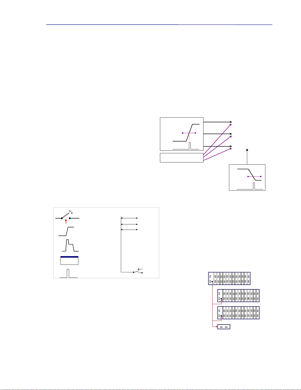
2.3.2. Triggers
The PowerSync Analyzer has extensive triggering capabilities, which are divided into 2 categories: internal (or waveform)
and external (or event). The instrument also has the ability to perform non-triggered measurements. The triggering types
are depicted in Figures 2.7 and 2.8. Also depicted in
Figure 2.7 are trigger applications including the DC
meters, time-interval measurement, and load current
transient, each of which can be initiated with those
triggers.
Internal (or waveform) triggering is derived from the
common mode voltage levels received from the PSE
under test. For most measurements, this triggering is
based upon the trigger levels and directions (rising or
falling) set for Trigger 1. A second trigger, Trigger 2 is
used exclusively for terminating time interval
measurements. Trigger 2 offers identical
programmability as Trigger 1 (levels and edge polarities).
External (or Event) triggering is also used to initiate measurements or actions, and is initiated by either a user command, an
action that is programmed to send out an external trigger, or
through an external event that appears on the trigger bus.
The trigger bus is a trigger signal connection that is shared by
all ports within a system, and by the Trig Out BNC connector
on each PowerSync Analyzer. Figure 2.8 shows the sources
used to generate External (or event) triggers on the left, and
shows the external bus configuration on the right.
Any External trigger
in the system will
appear on this bus, and
will trigger any port
which is waiting for an
external trigger event. This enables cross-triggering across ports and triggering via
externally generated signals. It also enables the user to use the trigger output for
other purposes, such as monitoring data throughput during PSE powering or load
transients.
The BNC trigger connector on the Chassis Controller front panel can be configured
as an output or an input. As an output, it directly mirrors the External trigger bus.
Output triggers will appear as a 3.3V, 10 mSec pulse. When set as an input, it can
drive the external trigger bus inside the PSA chassis. This enables triggering across
multiple instruments, which may be desirable when testing equipment with more than 24 ports.
Voltage
Trigger 1
Level
DC Meters
Current Transient
Time Interval Meter
Internal Trigger
External Trigger
Voltage
Trigger 2
Level
Trigger 2
Voltage
Trigger 1
Level
DC Meters
Current Transient
Time Interval Meter
Internal Trigger
External Trigger
Voltage
Trigger 2
Level
Trigger 2
Figure 2.7 Test Port Triggering
Port Switch
(Connect or Isolate)
Current
Current
Static Load Change
Load Transient
Software “TrigOut”
(or Send Trigger)
> trigout
Another Port
5 Sources External
Trigger Bus Slot1, Port1
Slot1, Port2
Slot2, Port1
…..
Chassis
Ext. Trigger
(Optional)
(Optional)
(Optional)
Port Switch
(Connect or Isolate)
Current
Current
Static Load Change
Load Transient
Software “TrigOut”
(or Send Trigger)
> trigout> trigout
Another Port
5 Sources External
Trigger Bus Slot1, Port1
Slot1, Port2
Slot2, Port1
…..
Chassis
Ext. Trigger
(Optional)
(Optional)
(Optional)
Figure 2.8 PSA Test Port Trigger Sources
PSA #1
PSA #2
PSA #3
PSA #4
External Trigger
PSA #1
PSA #2
PSA #3
PSA #4
PSA #1
PSA #2
PSA #3
PSA #4
External Trigger
Figure 2.9 External Trigger Bus

PowerSync Service Analyzer Reference Manual
February 8, 2010 Sifos Technologies page
14
For example, the Figure 2.9 shows cross triggering across instruments. The trigger direction on PSA #1 is set as an output,
and the other PSA’s are set as inputs. This set-up can be used to perform measurements, or initiate a load current change
across 96 or more PoE ports simultaneously.
2.3.3. Loads and Load Transients
The load and load transients subsystem uses an active programmable current load. This current load is activated for port
voltages in excess of 15V from the PSE under test. Similarly, the load is deactivated when the port voltage drops below
15VDC. The current load has a programmable range from 0 through 511 mA, in 0.5 mA steps. The PowerSync
Analyzer’s active load may also be configured to produce a programmable 2-step transient current load, where both current
level and load step durations can be set. The durations are programmable from 200 μSecs to 1 second per step. The second
step can optionally be held indefinitely thus becoming the new static DC load. The load transient can be triggered via
either Trigger 1 (waveform) or Externally (event), and it is also capable of generating an Event Trigger at the beginning of
the transient. The load circuitry is automatically switched out of the circuit for input voltages lower than 15V.
2.3.4. DC Meters
The DC Meter subsystem is capable of measuring PSE voltages and sensing actual load currents. Measurement
capabilities include average, maximum peak, minimum peak, and trace capture of either voltage or current. Each of these
measurements uses configurable measurement periods from 10 mSecs to 10 seconds. The sampling rates scale with
measurement period, and range from 40us to 40 mSecs for 10 mSec and 10 second measurement periods respectively.
All DC Meter measurements can be user initiated, triggered with a designated voltage transition and level, or triggered via
an external event (see Section 2.3.2). Only one DC measurement can be performed at a time on a each test port. Triggered
measurements across multiple test ports may be configured to run simultaneously however using either port-specific
waveform triggering or shared external triggering.
2.3.5. AC Meter
The AC Meter is used to measure ripple voltage on the DC signal supplied by the PSE under test. This measurement is
always initiated upon receipt of the AC measurement command.
The AC Meter is capable of measuring ripple in either a 16 Hz – 5K Hz band, or in a 5K – 300K Hz band (3dB BW). This
measurement is a peak-to-peak voltage measurement, based upon a sample rate of approximately 20K-samples per second.
Since this is a peak-to-peak measurement of ripple on a steady state voltage, there are no triggers associated with this
measurement. Integration period can be programmed from 10msec to 5 seconds in 1,2,5 scale increments.
2.3.6. Time Interval Meter
The time interval meter measures time duration between a Trigger 1 edge transition or an External Trigger event, and a
Trigger 2 edge transition. This measurement is configured either to 1 mSec or 1 μSec resolution scale, and can be used for
measurements of reaction times, rise times, pulse widths, and other time-critical events.
If the timing measurement exceeds the maximum capacity of the counters, an “overflow” condition will be returned. The
maximum measurable time intervals are 52.4 mSecs and 6.7 seconds for the 1 µSec and 1 mSec scales respectively. The
resolution for the mSec range is 0.1 mSec and the resolution for the µSec range is 1 µSec. The minimum measurable time
interval is 20 µSec.
2.3.7. LAN Test “Data OUT” Ports
Each test port provides a passively de-coupled “output” to enable the testing of LAN packet throughput either with or
without PoE loads applied. Testing under conditions of PoE load can be used to resolve any significant contribution of
PoE voltage and current toward packet transmission impairment. Such testing can be performed using 10BaseT
(Ethernet), 100BaseT (Fast Ethernet), and 1000BaseT (Gigabit Ethernet) signals. Packet transmission latency through a
PSA Test Port will be negligible owing to the simple passive coupling.
Because the primary purpose of the instrument is to accurately resolve numerous Power-over-Ethernet behaviors, the LAN
pass-thru channel is not optimized for LAN transmission per applicable IEEE 802.3 and ANSI/EIA/TIA standards. Users
should expect that the PSA test port will add a small degree of impairment, particularly affecting low frequency response of
the LAN channel. This impairment may lead to very low levels of packet loss depending upon characteristics of connected
LAN PHY’s. Such characteristics may either worsen or help overcome effects of baseline wander and low frequency
response. Sifos does not specify any particular level of performance for the Data OUT port because performance is
strongly influenced by physical layer design characteristics of LAN ports (e.g. packet data testers, PSE ports) that are
connected to the PSA Test Ports.

PowerSync Service Analyzer Reference Manual
February 8, 2010 Sifos Technologies page
15
Also, because many LAN terminations include various methods of EMI suppression (e.g. “Bob Smith termination”), Sifos
recommends that the OUT port not be connected to a LAN analyzer or other Ethernet device when running precision PoE
signaling measurements including the optional PSE Conformance Test Suite available for PSA-1200 platforms since
these can devices can present unpredictable AC loads and impairments that will negatively affect those PoE signals.
2.4. System Software Overview
PowerSync Analyzers require externally hosted software in order
to operate. PSA software is primarily designed for the Microsoft
Windows operating environment. A version is also available for
Linux and Unix based hosts. PSA software consists of several
distinct subsystems:
PSA Interactive: A graphical user interface designed to
promote interactive use of the PSA1200 or PSA-PL instrument.
PowerShell: A scripting and application program development
environment for creating and executing automated test
sequences. The PowerShell script development environment is
built upon the Tcl/Tk scripting language.
PSE Conformance Test Suite: A series of applications
developed specifically for conformance testing PSE ports to the
802.3 PoE specification given an PSA-1200 platform.
PSE Multi-Port Test Suite: A series of applications developed specifically for system performance testing PSE power
management, capacity, and multi-port decision behaviors.
PoE Service Analyzer: A set of applications and tools for in-depth analysis of PoE Service characteristics at the PD
interface available for the PSA-1200 platform.
PowerShell includes a robust set of commands added into Tcl/Tk that create the Application Programming Interface (API)
for the PowerSync Analyzer family of instruments. Both PSA Interactive and each of the test suites fully utilize the
PowerShell API to control and monitor the PSA. This assures complete uniformity of behaviors when the instrument is
configured from either the PowerShell interface or from PSA Interactive.
2.4.1. PSA Interactive
PSA Interactive is a Tcl/Tk based graphical user interface (GUI) constructed on top of the PowerShell API. It offers robust
control of most PowerSync Analyzer functions. It is intended for users who intermittently or regularly use the PowerSync
Analyzer for PD emulation and PSE measurements as well as for PSE Conformance (PSA-1200) and PSE Multi-Port
(PSA-1200 and PSA-PL) testing.
2.4.2. PowerShell Scripting Environment
PowerShell provides command level access to the PowerSync Analyzer. It consists of the full Tcl/Tk programming shells
(Tcl and Wish) combined with numerous extensions specific to the PowerSync Analyzer.
Tcl/Tk offers two shell programs for interactive command / query execution and scripting development. The “classic” Tcl
shell is an interpretive development environment for Tcl command and script execution. In Windows, the Tcl shell is
typically the Windows command shell with the full range of Tcl libraries (command set) packaged in.
Many operating system (e.g. “MS DOS”, Linux “Bash”) commands also execute in this shell.
The Wish shell enables Tk extensions useful for developing graphical user interfaces. As a shell program, Wish is more
“Windows-like” in its support of a mouse controlled cursor as well as its cut and paste editing capabilities. It does impose
certain limitations in the handling of “standard input” (interactive user prompting) however.
For the most part, PowerShell commands and scripts run equivalently in either the Tcl Shell or the Wish Shell, so users are
generally free to use the shell that best suits their needs. When PSA software is installed, certain configuration files will be
placed such that opening either the Tcl Shell or the Wish Shell will automatically integrate all of the PowerShell resources.
Figure 2.10 PSA Host Software Architecture
PSA Interactive
Graphical User
Interface Software PSE Test Suites
Conformance Suite
(excluding PSA-PL)
Multi-Port Suite
PoE Service Analyzer
(excluding PSA-PL)
PowerShell
TK/Tcl Based Application
Development Environment
10/100BaseT
Tk/Tcl 8.4.5
API
Tk/Tcl
Libraries
PowerSync Analyzer Software
Config
File(s)
Reports
PowerSync Analyzer
PSA Interactive
Graphical User
Interface Software PSE Test Suites
Conformance Suite
(excluding PSA-PL)
Multi-Port Suite
PoE Service Analyzer
(excluding PSA-PL)
PowerShell
TK/Tcl Based Application
Development Environment
10/100BaseT
Tk/Tcl 8.4.5
API
Tk/Tcl
Libraries
PowerSync Analyzer Software
Config
File(s)
ReportsReports
PowerSync Analyzer

PowerSync Service Analyzer Reference Manual
February 8, 2010 Sifos Technologies page
16
Many test engineers will want to integrate PowerShell API into pre-existing script environments to support test automation
involving several instruments including DUT control interaction. The final chapter of this manual addresses PowerShell
features designed to enable this possibility.
2.4.3. PSE Automated Test Suites
The PSE Conformance Test Suite is an optional feature of the PSA-1200 (including PSA-100, PSA-2400) consisting of
23 tests and associated utilities that run in PowerShell and can be accessed and sequenced from either PowerShell or from
PSA Interactive. These tests are designed to assess 802.3af and 802.3at compliance of one or more PSE ports. The tests
cover detection, classification, power-up, power management, MPS, and power-down behaviors of PSE ports. The tests
have been constructed to work as generally as possible given the wide range of signaling and other PSE characteristics
described above in Section 2.2. Each test returns one or more specification parameters relating to the 802.3 PoE
specification.
The PSE Multi-Port Test Suite is an optional feature of the PSA-1200 (including PSA-2400) and PSA-PL consisting of
16 tests that automatically analyze PSE system powering characteristics including bulk power-on, power-down, and
overload processing characteristics as well as power management, power capacity, and stress test behaviors. Each test
returns a variety of multi-port statistics and offers the capability to generate detailed logs of PSE port interactions and
timing behaviors.
The PoE Service Analyzer is the aimed at qualifying PoE service delivered to a PD at the PD interface point. It evaluates
basic service capabilities, many interoperability parameters, and classification or power management behaviors of the PoE
service. This feature is available on all PSA-1200, PSA-100, and PSA-2400 platforms.
Each test suite includes a test sequencer and several report generation options including automatic Microsoft Excel
spreadsheet that reports test results, test statistics, test limits, and pass/fail results on one or more cycles of testing.
2.4.4. PowerSync Analyzer Configuration Files
PowerSync Analyzer software utilizes two local configuration files that can be adapted for a number of characteristics that
are “local” to a user’s setup and testing requirements. These files are located as follows:
Operating System Config Directory Location
Windows NT – Windows XP \Program Files\Sifos\PSA1200\Config\
Windows Vista & Windows 7 \Users\Public\Sifos\PSA1200\Config\
Linux & Unix $HOME/Sifos/PSA1200/Config/
The PSA Environment local configuration file is named psa_env.txt. This file is found in the subdirectory \env\ (or /env/
for Linux) beneath the above mentioned Config directory location. Only one instance of this configuration can exist in the
host computer. It contains system environment related parameters as described in the following table:
Parameter Type Parameter Values
Default_PSA_Address: <current PSA IP address>
PSA_Addresses: {<TCL List of known PSA IP addresses>}
Default_Conf_Test_List_AF: {<TCL List PSE Conformance Tests>}
Default_Conf_Test_List_AT: {<TCL List PSE Conformance Tests>}
Default_Test_Results_Path: {<TCL string of default path location for all test result files>}
Excel_Path_Location: {<TCL string of path route to MS Excel>}| “N/A”
Emulation_Mode: ON or OFF
I/O_Routing: psa
Default_PSA_Address: The PSA chassis to initially be controlled by the PowerShell and PSA Interactive when those
applications open up. This chassis will be automatically “inventoried” upon application initialization and initial PSA
connection. The address will be updated in this file whenever Select Chassis is performed via PSA Interactive or when the
psa command is executed in PowerShell assuming that the new address is valid and present.
PSA_Addresses: A (Tcl) list of “known” PSA Chassis addresses on the network. A Tcl list is enclosed in braces and uses
spaces to separate different elements (e.g. IP addresses). This list will evolve as new chassis are connected and selected by
either PSA Interactive or PowerShell.
Default_Conf_Test_List_AF: A (Tcl) list of available standard tests within the Version 3.4 PSE Conformance Test Suite
for 802.3af and pre-802.3at standard high power PSE’s.
Default_Conf_Test_List_AT: A (Tcl) list of available standard tests within the Version 4.0 PSE Conformance Test Suite
for 802.3at compliant PSE’s. Note: These tests are only available for the PSA-3000 platform.

PowerSync Service Analyzer Reference Manual
February 8, 2010 Sifos Technologies page
17
Default_Test_Results_Path: Path to where test results from the sequencer will be stored. This has the default value of
“c:/Program Files/Sifos/PSA1200/Results/<chassis IP Address>” when PSA software is initially installed. Note that PSE-
specific local configuration files may override this default (see below).
Excel_Path_Location: Path where Microsoft Excel application is stored. This is formed during installation.
Emulation_Mode: A control that allows software operation in the absence of a PowerSync Analyzer instrument. It is also
referred to as “Demo Mode”. This control should be normally set to “OFF”.
I/O_Routing: A control that should be normally set to “psa”.
A second type of configuration file is the Local PSE Configuration File for specific PSEs. These files generally (though
not necessarily) reside in the Config directory location described above. They must have .txt file extensions. There may
be more than one local configuration file, for example there may be one Local PSE Configuration File for each type of PSE
that a user plans to test.
The PSE Local Configuration file consists of the following settings:
Parameter Type Parameter Values Status
Default_PSE_Class: EndSpan or MidSpan Required
Default_PSE_MPS_Type: AC or DC Required
Default_ALT_Setting: Aor BRequired
Default_POL_Setting: MDI or MDI-X Required
PSE_High_Pwr_Grant: NONE or PHY or LLDP
PSE_Test_Results_Path: {<TCL string of path location for results files>}Optional
PSE_Conf_Test_Report: {<Non-standard Conformance Report template file>} Optional
PSE_MP_Test_Report: {<Non-standard Multi-Port Report template file>} Optional
Default_PSE_Class: Specifies whether the PSE is EndSpan or MidSpan equipment . This setting will be affected by the
PSE Type declaration in the PSE Conformance Test menus in PSA Interactive software and may also be configured in
PowerShell using the psaPseClass global variable. The PSE Class or Type is used to limit certain other PSE descriptors
(e.g. “LLDP” High Power Grant) and is fed to the PSE Conformance Standard Report for test limit processing.
Default_PSE_MPS_Type: Specifies whether PSE utilizes AC or DC MPS method to remove power from a PD. This
setting will be affected by the “DC MPS” vs “AC MPS” PSE Description controls in the PSA Interactive PSE
Conformance Test menus and Multi-Port Test Menus (see Section 3.3).
Default_ALT_Setting: Specifies how to initialize all ports within the PowerSync Programmable Load for ALT pair
selection. Initialization is performed ONLY when the local configuration file is loaded via the [File] [Load] operation in
PSA interactive or via the psa_pse ( = psa_getConfig) command in PowerShell. The [File] [Save] operation in PSA
Interactive or the psa_saveConfig command in PowerShell will store these settings using current PSA port configuration.
Initialization will automatically include all PSA chassis’ that make up a PSA-2400 RackPack PSA.
Default_POL_Setting: Specifies how to initialize all ports within the PowerSync Analyzer for PoE polarity (MDI vs
MDI-X). Initialization is performed ONLY when the local configuration file is loaded via the [File] [Load] operation in
PSA interactive or via the psa_pse ( = psa_getConfig) command in PowerShell. The [File] [Save] operation in PSA
Interactive or the psa_saveConfig command in PowerShell will save these settings using current PSA port configuration.
Initialization will automatically include all PSA chassis’ that make up a PSA-2400 RackPack PSA.
PSE_High_Pwr_Grant: Specifies the method used by a Type-2 PSE (as defined in IEEE 802.3at) to grant full power to a
Type-2 PD. Type-1, or 802.3af generation PSE’s must therefore specify NONE for this parameter since they are not
capable of delivering 30 Watts of power. Some PSE’s, such as Type-2 MidSpans, will specify PHY to indicate that they
use 2-event classification in response to a PD Class 4 signature to grant access to full power. Many Type-2 EndSpan
PSE’s may use Link Layer Discovery Protocol (LLDP) defined under 802.3at to grant access to full power – those PSE’s
will therefore use the LLDP setting. This setting is available under the PSE Conformance Test Menus in PSA Interactive
and may also be configured in PowerShell using the global psaPseHpGrant. As a setting it is used to gate access to high
power tests using Type-2 PD emulation, it is used to make decisions inside automated tests, and it is used by the
Conformance Test Standard Report in configuring test limits.

PowerSync Service Analyzer Reference Manual
February 8, 2010 Sifos Technologies page
18
PSE_Test_Results_Path: This parameter, if provided, will override the default test reporting path found in the
psa_env.txt environment file and guide all test results and reports to the specified directory path that can be PSE type or
model specific. NOTE: This setting can only be changed by editing the PSE local configuration file directly – the
setting is retained whenever a local configuration file is “loaded”, then “saved” by PSA Interactive or PowerShell.
PSE_Conf_Test_Report: Specifies a non-standard PSE Conformance Test template (spreadsheet) file for use by the PSE
Conformance Test Suite running on a PSA-1200 (or PSA-100, PSA-2400). An example might be a re-named copy of
psa_report.xls that has modified test limits for a particular PSE type. NOTE: This setting can only be changed by editing
the configuration file directly – the setting is retained whenever a local configuration file is “saved” by PSA Interactive
or PowerShell. See Section 5.10 of the PSA-1200 manual for further information.
PSE_MP_Test_Report: Specifies a non-standard PSE Multi-Port Test template (spreadsheet) file. An example might be
a re-named copy of mp_report.xls that has modified test limits for a particular PSE type. NOTE: This setting can only be
changed by editing the configuration file directly – the setting is retained whenever a local configuration file is “saved”
by PSA Interactive or PowerShell. See Section 6.11 for further information.
Note that changes to PSE Local Configuration Files required to make existing files compatible with PSA 3.4 Version
software will occur automatically after software is updated and those PSE Local Configuration Files are loaded or saved.
2.4.5. Directory and File Organization – Microsoft Windows
When PowerSync Analyzer software is installed to a Microsoft Windows®PC, files will be populated to particular
directories as described in the following table.
Directory Path Directory Files
PowerShell Script Library
PowerShell Wish and PowerShell Tcl Executables
PSA Initialization Script
PowerShell Wish and PowerShell Tcl resource files
\documentation\ Various PSA reference documents
C: \Program Files\Sifos\PSA1200
\PSA Interactive\ PSA Interactive Script Library and various library sub-
directories to support PSA Interactive functions (plotchart,
tkprint1.1, tbcload14, etc.).
PSA Interactive Executable
PSA Interactive resource file
\Config\ PSA (local) Configuration Files including \Config\env
environment file sub-directory.
\Results\ PSA Test Report Files
Including psa_report.xls, mp_report.xls, and
service_report.xls template report spreadsheets and the
psa_trace.xls trace display spreadsheet. Chassis-specific
subdirectories under \Results will automatically be created as
needed by PowerSync Analyzer software.
\Emul\ Files only used when PSAsoftware is placed in “Demo Mode”
(also called Emulation Mode).
Windows NT – Windows XP
C: \Program Files\Sifos\PSA1200
Windows Vista – Windows 7
C:\Users\Public\Sifos\PSA1200
\Contrib\ Tcl scripts stored in this directory will automatically source
into PowerShell. This directory includes various sample
scripts at installation.
Version information concerning individual PowerSync Analyzer software libraries is available from PSA Interactive under
the [Help] menu as well as from PowerShell using the psa_version command.
2.4.6. Directory and File Organization – Linux and Unix
PSA Software installs into Linux and Unix in a manner that separates and organizes files into 3 categories:
Category File Locations
Compiled Software and Libraries /usr/local/Sifos/PSA1200
Configuration and User Data <User’s Home Directory>/ Sifos/PSA1200
Shell Scripts (Program Launchers) <User’s Home Directory>/bin

PowerSync Service Analyzer Reference Manual
February 8, 2010 Sifos Technologies page
19
This organization allows various users in a shared computing or NFS type of environment to maintain local user
information independent from other users and independent of the actual shared software modules and libraries.
Installation of PSA Software requires that the user have full permissions to add the application into the /usr/local/ directory
path while the installation takes place. After installation, those permissions may be removed.
The following table provides greater detail regarding files and file locations after PSA software installation is completed.
Directory Path Directory Files
PowerShell Application Programs & Script Libraries
PowerShell Wish and PowerShell Tcl resource files
(unused copies)
/usr/local/Sifos/PSA1200
/PSA
Interactive/
PSA Interactive Application Programs & Script
Libraries
Shared Library Directories with binaries and scripts
used by PowerShell and PSA Interactive
Copy of PSA Interactive initialization resource file
PowerShell Wish and PowerShell Tcl resource files
(used by shell scripts to initialize PSA software)
/Config/ PSE (local) Configuration Files including /Config/env
environment file sub-directory.
/Results/ PSA Test Report Files
Including psa_report.xls, mp_report.xls, and
service_report.xls template report spreadsheets and
the psa_trace.xls trace display spreadsheet. Chassis-
specific subdirectories under \Results will
automatically be created as needed by PowerSync
Analyzer software.
/documentation/ Various PSA reference documents
/Emul/ Files only used when PSA software is placed in “Demo
Mode” (also called Emulation Mode).
<User Home Path>/
Sifos/PSA1200
/Contrib/ Tcl scripts stored in this directory will automatically
source into PowerShell. This directory includes
various sample scripts at installation.
<User Home Path>/ bin Shell scripts to launch:
PowerShell TCL (PowerShell_TCL.sh),
PowerShell Wish (PowerShell_Wish.sh)
PSA Interactive PL (PSA_Interactive.sh).
PSA Software Installer and Removal Scripts.
Version information concerning individual PowerSync Analyzer software libraries is available from PSA Interactive PL
under the Help menu as well as from PowerShell using the psa_version command.
2.4.7. TK/TCL Requirements & Resources
PowerSync Analyzer software was developed utilizing Tcl/Tk version 8.4.5. Generally, there should not be a problem with
using newer versions of Tcl/Tk. PSA software is distributed with an installer for Tcl/Tk 8.4.5 on Microsoft Windows
platforms. If Tcl/Tk is not present on the host PC system or if a version older than 8.4.5 is found, PSA installation software
will install version 8.4.5 Tcl. If a newer version (e.g. ActiveState Tcl 8.4.9) is already on the host system, PSA software
will utilize that version. (Note: This does not apply to Linux systems where the user is responsible for pre-installing a
satisfactory version of Tcl/Tk.)
While there are no requirements as to where the user installs Tcl/Tk, it is recommended that the install be done in the
c:\Program Files\tcl directory on Microsoft Windows systems and in /usr/local/ on Linux systems. Users should beware
that older or specially modified versions of Tcl present from installations of various LAN analyzer software tools and
applications could interfere with PSA software behavior.
PowerShell software includes four “resource” files: tclshrc.tcl, tclshrc_psapi.tcl, wishrc.tcl and wishrc_psapi.tcl.
These files are utilized by PowerShell during initialization and should remain in the directories where they are initially
installed. Sections 8.3 and 8.4 of this manual provide further information regarding PowerShell API integration into native
TCL shells as well as the use of these files to enable remote access to PowerShell.

PowerSync Service Analyzer Reference Manual
February 8, 2010 Sifos Technologies page
20
There are a number of valuable resources to help programmers and test engineers get acquainted with Tcl. First, the help
software that comes with Tcl/Tk is very robust and easy to work with. Also, there are several books available including
“Practical Programming in Tcl and Tk” by Brent B. Welch. On the Web, there are numerous “notes” sites with
correspondence on Tcl and Tk programming owing to Tcl’s popularity in academic and commercial enterprises.
2.5. (Section Omitted)
2.6. (Section Omitted)
2.7. Technical Specifications
2.7.1. Port Configuration
Input/Output Ports 1 & 2 RJ45, 10/100/1000BaseT 100ΩBalanced
Pair Connectivity Ports 1 & 2 Alt. A or Alt. B
Polarity Ports 1 & 2 MDI or MDI-X
Detection Resistance Ports 1 & 2 Range 8 to 39 KΩ
Resolution 1KΩ
Accuracy 1%
Detection Capacitance Ports 1 & 2 Range 0.14, 5.14, 7.14, 11.14, 47,
52, 54, and 58 μF
Accuracy 5%
Load Current Ports 1 & 2 Range 0 to 511 mA
Resolution 0.5 mA
Error +
1.8% +1.1 mA
Activation Voltage 15.5V
Configurable Load Ports 1 & 2 Load Steps 2
Transient Range 200µs to 1sec
Resolution 100µs
2.7.2. Measurements
DC Voltage Pair-to-Pair Type Peak, Average, or Trace
Range 0 to 60V
Resolution 64mV
Error +
1.2% +13 mV
Peak Types Max or Min
Trace Length 256 Samples
Triggers Immediate, Internal, External
DC Current Powered Pair Type Peak, Average, or Trace
Range 0 to 511 mA
Resolution 0.5 mA
Error +
1.2% + .25mA
Peak Types Max or Min
Trace Length 256 Samples
Triggers Immediate, Internal, External
Voltage Ripple Pair-to-Pair Range 0 to 2Vpp
16Hz - 5kHz Resolution 4mV
Error TBD
%
Table of contents
Other Sifos Technologies Measuring Instrument manuals

Sifos Technologies
Sifos Technologies PSA-3000 User manual

Sifos Technologies
Sifos Technologies PowerSync PSA100 Product manual

Sifos Technologies
Sifos Technologies PowerSync PDA-300 User manual

Sifos Technologies
Sifos Technologies PowerSync PSA-3002-SA Product manual

Sifos Technologies
Sifos Technologies PowerSync PDA-300 Product manual

Sifos Technologies
Sifos Technologies PhyView PVA-3000 User manual

Sifos Technologies
Sifos Technologies PowerSync Series User manual

Sifos Technologies
Sifos Technologies PowerSync PSA100 User manual


