EASTONTECH EW Series User manual

EW-5010A OPERATION MANUAL
1
Edition No.: 2021 Rev 2
WENZHOU EAST WORLD IMPORT&EXPORT CO., LTD.
(CE, ISO9001)
EW Series Insulation Ferrule
Crimping Machine
Operation Manual
(FOR EW-5010A)
Add:Building No.2 丨Xingdong Industrial Park 丨NO.188 Wangxin Road 丨Dongshan
Street 丨Ruian 丨Zhejiang Province 丨China P.C.-325200
Website: www.ew-wirestripping.com
Email:kitty@ew-wirestripping.com
Tel/Fax:+86-0577-66603688

EW-5010A OPERATION MANUAL
2
Machine removal and installation
1. After taking out the machine, confirm whether there is any
transportation damage or other mechanical parts falling off in the
machine box.
2. After the machine is taken out, open the right box door and remove
the internal transport fixed part of the cable tie (as shown below left),
and take out the jig accessory box in the rubber waste box.
3. After taking out the jig accessory box, release the rubber waste box
until the magnet catches it.
4. Before ventilating, the rotating and swinging mechanism keeps the
vertical position (the position on the left below is vertical).
5. The air source and power interface are in front of and behind the
machine.

EW-5010A OPERATION MANUAL
3
Parameter
Name
Pre insulation terminal crimping machine
Model
EW-5010A
Control mode
human-machine interface, electronic control, pneumatic
control.
Operation mode
Automatic trigger operation and manual operation
Wire size
BVR wire 0.5、0.75、1.0、1.5、2.5、4.0mm2
Terminal size
Insulator length ≤7.5mm, conductor length≤10mm
Stripping length
Max. 17mm
Crimp Shape
Quadrilateral Crimp
Product replacement
Manual replacement of related parts, adjustment of vibration
plate and electric memory adjustment.
Production capacity
2.5s /wire (considered as a single cycle of the machine).
Detection items
terminal presence or absence,right side safety door open
detection.
Power source
External input power AC220V / 50Hz (single-phase) 10A;
internal power DC24V, DC12V
Air source
0.6-0.8Mpa (please use a stable, clean and dry air source, and
keep the air source at least 0.6 Mpa).
Working temperature
10~25℃
Operating humidity
30~80%HR (non-condensing)
Dimensions
W350mm×L450mm×H400mm (excluding protrusions)
weight
40KG

EW-5010A OPERATION MANUAL
4
ⅠInterface introduction
1.1 Home screen function introduction
1-1-1. Total production: The quantity counted by the machine during
production operation in automatic mode.
1-1-2. Total reset: reset the total output; the total reset button can be
displayed or closed in the administrator settings interface, but it will be
displayed automatically when the total production reaches the standard.
shut down.
1-1-3. Total setting: The quantity that can be set according to the
production needs (maximum setting value is 32000), and it will prompt
when the quantity produced in the automatic mode arrives.
1-1-4. Production capacity: The machine operates in automatic mode,
(the terminal time is not included when peeling and crimping, because in

EW-5010A OPERATION MANUAL
5
the automatic case, the cycle time is parallel to the manual take-up and
release time); The setting interface settings are displayed or closed.
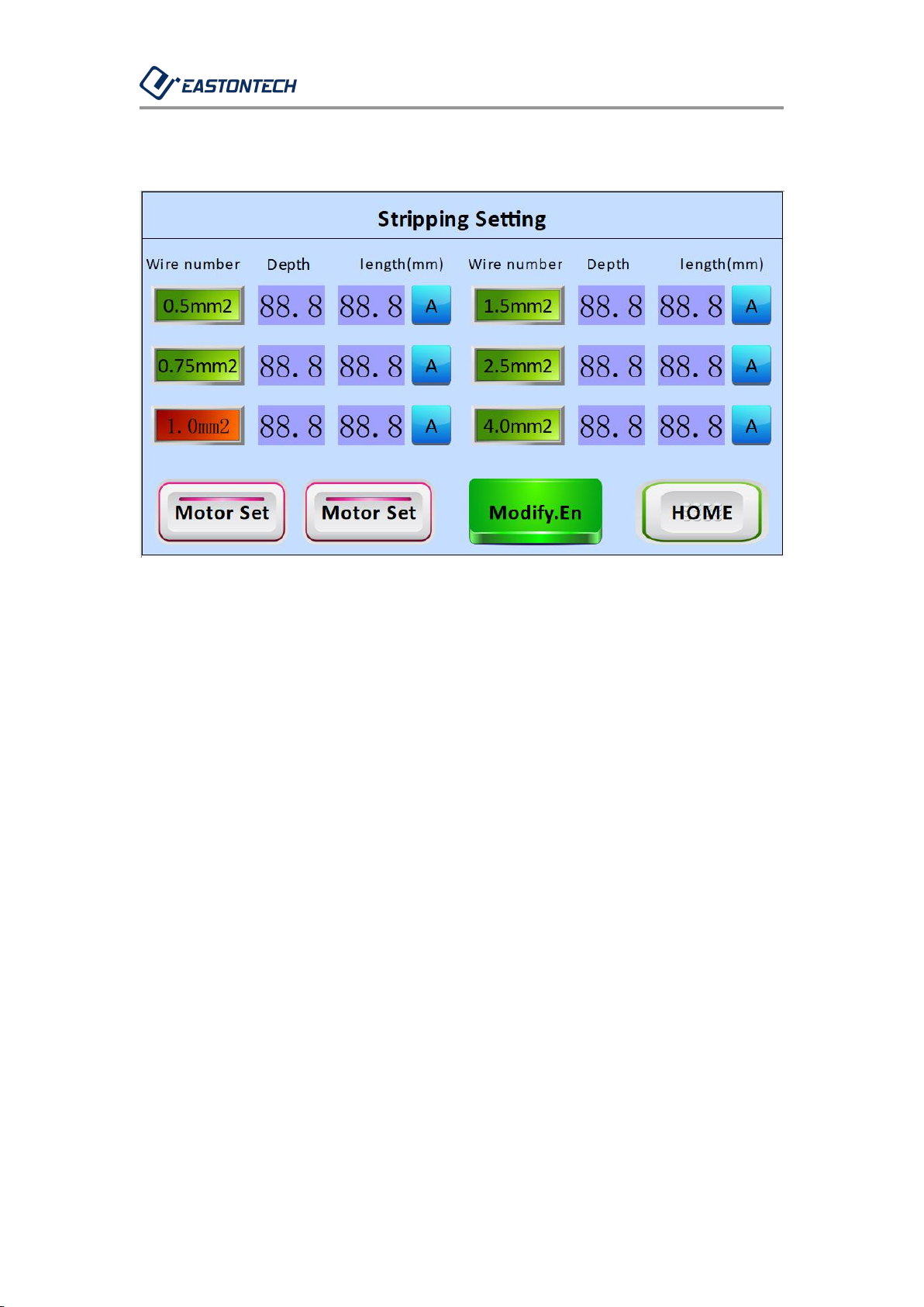
1-1-5. Peeling settings: pull down the menu key, see the related interface
for details.
1-1-6. Parameter setting: pull down the menu key. For details, please
refer to the related interface introduction.
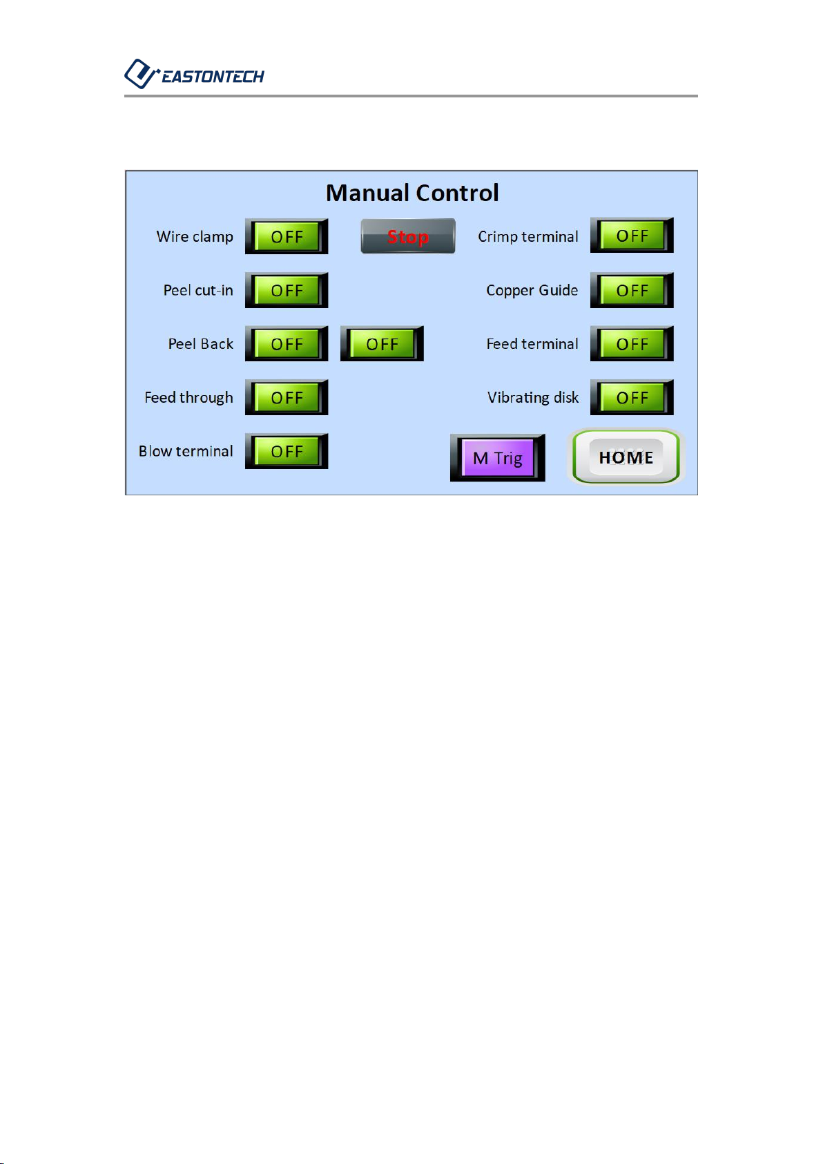
1-1-7. Manual control: pull down the menu button, see the related
interface for details.
1-1-8. Peeling and crimping: This button is a function selection, you can
click to switch to peeling.
1-1-9. Manual mode: This button is a function selection, you can click to
switch to automatic mode.
1-1-10. Jog: This button is used for jog control for single-step operation,
and it must be effective in the "manual mode"; the function is activated
when the jog button is pressed for about 2 seconds, and the background
color of the button turns red after startup , Click again to proceed to the
next action (click the next interval is valid for 1S).
1-1-11. The time in the upper right corner can be corrected in the system
settings interface.

EW-5010A OPERATION MANUAL
6
1.2 Manual control Introduction
1-2-1. Enter this interface: main screen → manual control.
1-2-2. 9 green buttons are jog self-locking switches, which need to be
jogged again to unlock; the initial state when OFF, and the output state
when ON; pay attention to safety during this operation to ensure
yourself and surrounding personnel Safe, especially during two
operations.
1-2-3.The "peeling and backing" cylinder has a safety operation
detection. For example, when the "penetration terminal" is already in
the operating state, the "peeling and backing" button will be locked.
Clicking is invalid.
1-2-4. The “Manual Trigger” button is in the automatic mode. You can
press and hold to start the automatic operation for a period (press and
hold time is related to the value in the parameter setting), which is

EW-5010A OPERATION MANUAL
7
equivalent to the automatic triggering of the line.
1-2-5. Main screen: Return to the main interface.

EW-5010A OPERATION MANUAL
8
1.3 Stripping Setting
1-3-1. Enter this interface: main screen → peeling settings.
1-3-2. There are a total of 6 wire number specifications for the peeling
setting. There is a corresponding settable value for each wire number.
Shallower.
1-3-3. There is a corresponding three stripping lengths for each wire
number stripping length. Click the A button as shown in the figure above.
Click once to switch to B, and then click to switch to C. Then click to
switch back to A
1-3-4. The larger the peeling length value, the longer the peeling length,
the smaller the value, the shorter the peeling length, and the unit of the
peeling length is mm.
1-3-5. When selecting the line number above and modifying the peeling

EW-5010A OPERATION MANUAL
9
depth or length, all are modified. Click "Modify Confirmation" to adjust
the actual position. After clicking Modify Confirmation, this key will
prompt the progress, and the selection or value cannot be modified at
this time.
1-3-6. After the machine is installed, the stripping depth and
corresponding stripping length of each line can be adjusted according to
different wire numbers. For example, after the stripping knife is replaced,
the stripping depth may vary. The size of the variation depends on the
processing accuracy of the stripping knife and Every installation position.
1-3-7. Motor setting: pull down the menu key, refer to the interface
introduction for details.
1-3-8. Main screen: Return to the main interface.

EW-5010A OPERATION MANUAL
10
1.4 Parameter set
1-4-1. enter this interface: main screen → parameter setting.
1-4-2. the above setting time is the time between sequence, setting
value × 10ms, except above special circumstances, no modification is
needed for the time being.
1-4-3. Main screen: Return to the main interface.

EW-5010A OPERATION MANUAL
11
1-4-4. Enter this interface: main screen → parameter setting → next
page.
1-4-5. The above setting time is the time between sequence, setting
value × 10ms. Except for special cases, the above time does not need to
be modified.
1-4-6. If the feeding terminal is not smoothly fed into the terminal guide,
you can modify the "blowing terminal delay time" to observe the actual
situation.
1-4-7. Main screen: Return to the main interface.

EW-5010A OPERATION MANUAL
12
1-4-8. Enter this interface: main screen → parameter setting → next
page → next page.
1-4-9. Delay start time of wire release touch: It can change the sensitivity
of wire release trigger. The smaller the value is, the more sensitive it is.
1-4-10. Delayed start time for resetting the pay-off trigger: that is, after
the crimping is completed, the next trigger will take effect after the delay,
and the trigger will not be triggered again when the wire is taken slowly.
You can adjust this time according to the worker's wire take speed
Cooperate.
1-4-11. Main screen: Return to the main interface.

EW-5010A OPERATION MANUAL
13
1.5 IO monitoring
1-5-1. Enter this interface: main screen → parameter setting → IO
monitoring.
1-5-2. Under normal standby conditions, only the above 4 input monitors
are displayed in red and the others are gray.
1-5-3. Main screen: Return to the main interface.

EW-5010A OPERATION MANUAL
14
ⅡChange product adjustment
2.1 Vibration plate feed adjustment
(Figure 212) (Figure 213) (Figure 214)
2-1-1. Figure 211 are the names of the parts supplied by the vibrating
plate.
2-1-2. Figure 212 shows the controller of the vibrating disk. This screen
shows the voltage H100. When the feeding speed of the various
terminals is too fast or too slow, you can press the up and down buttons
to adjust the voltage to the proper value. Usually, the terminal is first put.

EW-5010A OPERATION MANUAL
15
Observe whether to adjust.
2-1-3. Figure 213 This screen is displayed as frequency E50; only
frequency E50 and E100 are selected. A frequency E50 has been selected
when the machine leaves the factory, so no adjustment is required when
changing terminals (except for special cases).
2-1-4. Figure 214 is the amplifier with or without terminal induction; the
green number is the set value (default 500), the red number is the
current value; the red dot to the left of the green number is red when a
terminal is detected, no The terminal is off; there are buttons on the
right side of the red number, and the two rightmost up and down
buttons are for setting value adjustment.
(Figure 215) (Figure 216)
2-1-5. First confirm the terminal specifications that need to be changed,
and confirm whether to adjust the discharge guide 1 and the discharge
guide 2.
2-1-6. Adaptation of the discharge width of the discharge guide 1: 0.5,
0.75, 1.0 square can use 1.0 square as a reference for adjusting the width.

EW-5010A OPERATION MANUAL
16
After 1.0 square is adjusted, 0.75 and 0.5 square can also be used;
1.5 and 2.5 squares can use 2.5 squares as a reference for adjusting the
width. After adjusting 2.5 squares and using them, 1.5 and 2.5 squares
can also be used (the above general may be related to changes in the
size of each manufacturer's terminal specifications).
2-1-7. Discharging guide 1: For infinite adjustment, loosen 2 M4 bolts
and slide up and down to a suitable width (see Figure 215);
2-1-8. Discharging guide rail 2: As shown in Figure 216, there are three
clamping positions of the discharging rail 2, which can be adjusted by
loosening two M4 bolts; 0.5, 0.75, and 1.0 squares are the minimum
clamping positions, 1.5 and 2.5 square Is the middle card position, and
4.5 square is the maximum card position.
(Figure 217) (Figure 218)
2-1-9. Figure 217 shows the installation of the terminal guide. Pay
attention to the installation direction. The small sides of the small U port

EW-5010A OPERATION MANUAL
17
and the middle U port are to the right of the discharge direction; (see
Figure 217). Can be replaced by loosening M3-6 bolts .
2-1-10. Confirm the terminal specifications and whether to replace them.
There are three types of terminal guides: 0.5, 0.75, 1.0 square for the
smallest U port, 1.5, 2.5 square for the middle U port, and 4.0 square for
the maximum U port.
2-1-11. and Figure 218 are the terminal guide ring selection. The 6 U
ports of the terminal guide ring are suitable for 0.5, 0.75, 1.0, 1.5, 2.5,
and 4.0 square terminals.
2-1-12. Rotate the terminal guide ring by grasping the screw and pulling
it upward, select a suitable U port, and press it into the card position
again.

EW-5010A OPERATION MANUAL
18
2.2 Gig box

EW-5010A OPERATION MANUAL
19
2.3 Change jig and adjust
(Figure 221) (Figure 222)
2-3-1. Confirm the terminal specifications. There are 6 specifications for
the terminal guide rings of 0.5, 0.75, 1.0, 1.5, 2.5, and 4.0 square.
2-3-2. Figure 221, loosen the terminal guide ring M2.5-21.5 bolts (just
loosen one turn), and then tighten the specifications required for
replacement.
2-3-3. Confirm the terminal specifications. There are 5 specifications for
the copper core guide of 0.5, 0.75-1.0, 1.5, 2.5, and 4.0 square.
2-3-4. Figure 222, loosen the copper core guide M2.5-6 bolts, and
pre-lock the specifications required for replacement.
2-3-5. Put one selected terminal into the terminal guide ring for copper
core guide A and B alignment, as shown in Figure 221, leave a gap of
about 0.1mm to 0.2mm between the terminal and copper core guide.
Then, lock the copper core guides A and B. The locked copper core

EW-5010A OPERATION MANUAL
20
guides A and B must be flush with each other. Observe whether the
slopes of the guide cones completely match.
Other manuals for EW Series
2
This manual suits for next models
1
Other EASTONTECH Industrial Equipment manuals
Popular Industrial Equipment manuals by other brands

HYDAC International
HYDAC International AquaSensor AS2000 Series Additional instructions

ABB
ABB HT562960 Operation manual

Dillon Precision Products
Dillon Precision Products RL550C Assembly and user instructions

Jäger
Jäger Z120-H824.11 K1RW2V manual

Bungard
Bungard Splash Translation of the original instructions

Biber
Biber OSK85 operating instructions