ALFRA 03910 User manual

1
Bedienungsanleitung / Operation Manual /
Mode d’emploi / Manual de instrucciones /
Istruzioni per l’uso
Stromschienen Biege- und Lochstanzgerät
Busbar bending and punching machine
Appareil de pliage et de perçage de barres conductrices
Dobladora y punzonadora de barras colectoras
Piegatrice e punzonatrice di sbarre collettrici
Artikel-Nr. Komplett-Set 1: 03910 / Article Nr. Complete Set 1: 03910 / Article n° set complet 1: 03910 /
Nº de artículo set completo 1: 03910 / N. articolo set completo 1: 03910
Artikel-Nr. Komplett-Set 2: 03920 / Article Nr. Complete Set 1: 03920 / Article n° set complet 2: 03920 /
Nº de artículo set completo 2: 03920 / N. articolo set completo 2: 03920

2
Inhaltsverzeichnis / Contents / Table des matières / Contenido / Indice
Bestimmungsgemäße Verwendung, Beschreibung der Maschine,
Technische Daten / Lieferumfang, Inbetriebnahme,
Stromschienen biegen, Lochstanzen, EG-Konformitätserklärung,
Zubehör, Explosionszeichnung, Stückliste, Schaltplan.
Vor Inbetriebnahme
lesen und
aufbewahren!
Seite 3
Appropriate use, Description of the machine, Technical data /
Scope of supply, Commissioning, Bending busbars,
Holepunching, EC Declaration of Conformity, Accessories,
Exploded drawing, Parts list, Circuit diagram.
Please read and
keep these
instructions!
Page 14
Utilisation conforme, Description de la machine, Caractéristiques
techniques / Contenu de la livraison, Mise en service, Pliage de
barres conductrices, Perçage, Déclaration de conformité CE,
Accessoires, Dessin sous forme éclatée, Liste des pièces,
Schéma de connexions.
À lire avant la mise
en service puis à
conserver !
Page 25
Uso previsto, descripción de la máquina, datos técnicos /
volumen de suministro, puesta en marcha, doblar barras
colectoras, punzonar, declaración CE de conformidad,
accesorios, despiece, lista de componentes, esquema de
conexiones.
¡Leer atentamente
antes de la puesta
en marcha y
conservar!
Página 36
Uso appropriato, Descrizione della macchina, Dati tecnici /
Volume della fornitura, Messa in funzione, Piegatura delle sbarre
collettrici, Punzonatura, Dichiarazione di conformità CE,
Accessori, Vista esplosa, Lista dei pezzi, Schema elettrico.
Leggere
attentamente prima
della messa in
funzione e
conservare!
Pagina 47

3
Bestimmungsgemäße Verwendung
Mit dem Stromschienen Biege- und Lochstanzgerät können mit Hilfe des Universal-Arbeitszylinders Kupfer- und
Aluminiumschienen bis 120 mm Breite und 12 mm Stärke gebogen werden. Es können Löcher und Langlöcher von
Durchmesser 6,6 mm bis 21,5 mm und einer Länge bis 21,0 mm gestanzt werden. Die Nutzung sollte nur mit den von
ALFRA gelieferten Hydraulikpumpen AHP 03 und SC05 III-B erfolgen.
Beschreibung der Maschine
Das Stromschienen Biege- und Lochstanzgerät kann für das Stanzen und Biegen von Kupfer und Aluminiumschienen
eingesetzt werden. Die Steuerung erfolgt über die 3 Taster „START“, „STOP“ und „OUT“ (3,2,1) an der Frontseite des
Gerätes. Desweiteren ist die Schutzhaube (8) mit einem Sicherheitssachalter ausgestattet, sodass der Arbeitsvorgang
jederzeit durch ein leichtes anheben der Schutzhaube unterbrochen werden kann. Die Arbeitseinheit (7) kann mit
verschiedenen Werkzeugkombinationen bestückt werden, die ein Lochen und Biegen der Halbzeuge gestattet. Der
gewünschte Arbeitsprozess muss mit dem Wahlschalter (5) für Biegen/ Lochen ausgewählt werden. Die
Höheneistellung der Arbeitseinheit mit den Werkzeugen erfolgt mittels des Handrads (12) und kann über die
Höhenanzeige (11) überprüft werden. Eine genaue Beschreibung der Arbeitsvorgänge Biegen/ Lochen erfolgt im
weiteren Verlauf der Bedienungsanleitung.
1
„OUT“ Taster
7
Arbeitseinheit
2
„STOP“ Taster
8
Schutzhaube
3
„START“ Taster
9
Längenanschlag
4
Anschluss für Fußschalter 03861
10
Hydraulik Schnellkupplung
5
Wahlschalter Biegen / Lochen
11
Höhenanzeige
6
Anschluss für Steuerkabel der Pumpe/ Fußschalter 03865
12
Handrad für Höheneinstellung
1
2
3
4
4
5
6
8
9
10
11
12
7

4
Technische Daten / Lieferumfang
Gerät:
Außenmaße L x B x H:
700 x 410 x 410 mm
Gewicht:
60 kg
Max. Betriebsdruck:
700 bar
Biegen:
Lochen:
Biegen Cu + Al max.:
120 x 12 mm
Stanzen Cu + Al:
6,6 –21,5
auch Langloch bis max. L = 21 mm
Biegewinkel bis:
Über 90°
Materialstärke max:
12 mm
kleinste Schenkellänge:
50 mm
Materialbreite:
110 mm mittig
kleinstes U-Biegen:
100 mm
kleinstes Z-Biegen:
72 mm
(materialstärkenabhänging)
Lieferumfang:
Art.Nr. 03200
Art.Nr. 03910 Komplett-Set 1
Art.Nr. 03920 Komplett-Set 1
1 x Grundgerät
1 x Sicherheitshaube
1 x Steuerkabel
1 x Grundgerät
1 x Sicherheitshaube
1 x Steuerkabel
1 x Art.Nr. 03201 el. Winkelableser R10
1 x Art.Nr. 03202 Biegematrize R10
1 x Art.Nr. 03203 Längenanschlag
1 x Art.Nr. 03852 Elektrohydraulik-Pumpe
SC05 III-B
1 x 2 m Hydraulikschlauch
(mit 2 Schnellkupplungen)
1 x Grundgerät
1 x Sicherheitshaube
1 x Steuerkabel
1 x Art.Nr. 03201 el. Winkelableser R10
1 x Art.Nr. 03202 Biegematrize R10
1 x Art.Nr. 03203 Längenanschlag
1 x Art.Nr. 03853 Elektrohydraulik-Pumpe
AHP 03-1
1 x 2 m Hydraulikschlauch
(mit einer Schnellkupplung)
Inbetriebnahme
1. An der Gehäuserückseite der jeweiligen Pumpe befindet sich eine orangefarbene Belüftungsschraube. Diese muss
vor Inbetriebnahme der Pumpe in die Tanköffnung eingesetzt werden. Sie ersetzt die Ölverschlussschraube und
garantiert eine ausreichende Belüftung des Öltanks.
Transport Betrieb
SC05 III-B
AHP 03-1
2. Vor der Inbetriebnahme des Biege- und Lochstanzgeräts und der Hydraulikpumpe verbinden Sie den mitgelieferten
Hydraulikschlauch mit der Pumpe und dem Arbeitszylinder über die Schnellkupplungen.
3. Schließen Sie das Steuerkabel (5-Pol Anschlüsse) an.
Ölverschlußschraube

5
4. Schließen Sie die Hydraulikpumpe ans Netz an. Überprüfen Sie vorher die auf dem Gerät angegebene
Eingangsspannung/ Netzfrequenz mit den Daten ihres elektrischen Anschlusses.
5. Stellen Sie die Betriebsart am Grundgerät auf „Biegen“ oder „Stanzen“ ein.
Nur dann sprechen die Sicherheitssensoren am Gerät an.
6. Mit den Bedientasten „Start“, „Stop“ und „Out“ am Grundgerät wird das Biege- und Lochstanzgerät bedient.
Sofern Sie einen Fußschalter (Art.Nr. 03861) mitbestellt haben, können Sie diesen an die Anschlussdose (4)
anschließen und anstelle der Starttaste verwenden. Mit dem 3-Pedaligem Fußschalter (Art.Nr. 03865), der
zwischen die Hydraulikpumpe und der Anschlussdose (6) angeschlossen wird, können Sie sämtliche „START“,
„STOP“ und „OUT“ Funktionen bedienen.
Für andere, als in dieser Anleitung zugelassene, Antriebsaggregate übernehmen
wir keine Gewährleistung.
Stromschienen biegen
1. Stellen Sie den Schalter am Grundgerät auf „Biegen“.
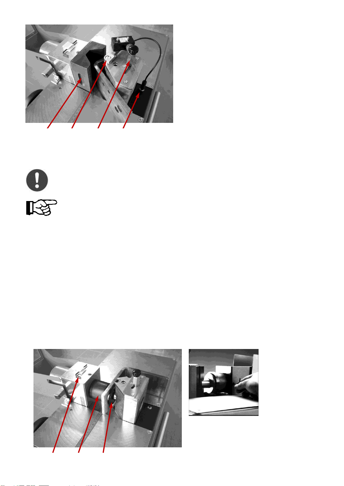
2. Setzen Sie die Biegematrize in den Hydraulikzylinder ein.
3. Schieben Sie den elektrischen Winkelableser in die runde Führungsnut des Gegenblocks.
Als Zubehörteil ist auch ein digitaler Winkelableser unter der Art.Nr. 03229 lieferbar.
4. Schließen Sie das Verbindungskabel an der Buchse auf der Rückseite des Arbeitsblocks an.
5. Fixieren Sie den Winkel auf der Winkelskala mit der Stellschraube.
Wir empfehlen Ihnen, je nach Materialstärke, 1-3° über den gewünschten Biegewinkel hinaus
einzustellen, da das Material zurückfedert.
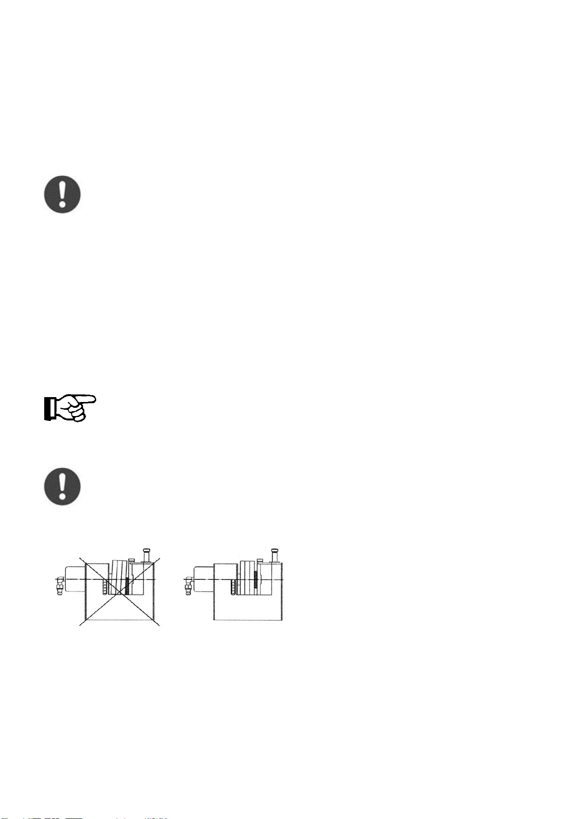
6. Stellen Sie den Arbeitsblock mit Hilfe des Handrads auf die Höhe ein, die der halben Breite der Stromschiene
entspricht.
Stromschienen beim Biegen immer mittig zentrieren.
7. Schließen Sie die Sicherheitshaube.
8. Durch Betätigung der „Start“-Taste wird der Biegevorgang ausgelöst.
Wenn der eingeleitete Arbeitsgang unterbrochen werden soll, genügt ein leichtes Anheben der Schutzhaube oder das
Betätigen der „Stop“-Taste. Der Hydraulikzylinder verbleibt in seiner momentanen Stellung. Um den Arbeitsprozess
fortzusetzen, schließen Sie die Sicherheitshaube wieder und betätigen Sie erneut die „Start“-Taste.
Bei Betätigung der „Out“-Taste wird der Hydraulikzylinder in die Ausgangsstellung zurückgeführt.

6
Lochstanzen
Nur mit scharfen Stempeln und Matrizen arbeiten.
Ölen Sie den Stempel leicht ein, um das Zurückziehen zu vereinfachen.
1. Stellen Sie den Schalter am Grundgerät auf „Lochen“.
2. Zum Lochstanzen nehmen Sie die Biegematrize und den elektrischen Winkelableser aus dem Arbeitsblock.
3. Setzen Sie den Stempel mit Neoprenabstreifer und Druckplatte (bis 14 mm Durchmesser) in die Aufnahmebohrung
des Arbeitsblocks ein.
4. Fixieren Sie die Stempelaufnahme mit dem Gewindestift gegenüber der Höhenanzeige. Benutzen Sie hierzu den
mitgelieferten Schlüssel.
5. Körnen Sie das Lochbild an der Stromschiene an.
6. Stellen Sie den Arbeitszylinder mit Hilfe des Zählwerks in den Stanzmittelpunkt.
7. Setzen Sie die Zentrierspitze des Stempels in den Körnerpunkt. Dadurch läßt sich das zu stanzende Lochmuster
exakt herstellen.
8. Nach beendetem Vorgang fährt der Lochstempel in die Ausgangsstellung zurück.
17
Inbusschlüssel
18
Matrize zum Lochen
19
Stempel zum Lochen
13
14
15
16
13
Biegematrize
14
Biegedorn mit Präzisionsschalter
15
Einstellschraube für Biegewinkel
16
Anschlussbuchse für elektr. Schalter
19
18
17

7
Markus A. Döring
(Geschäftsführer)
EG-Konformitätserklärung
Hiermit erklären wir:
Alfra GmbH
2. Industriestraße 10
68766 Hockenheim
dass das Produkt
Bauart: Stromschienen Biege- und Lochstanzgerät
Art.Nr.: 03200
in der serienmäßigen Ausführung mit dem vom TÜV Berlin-Brandenburg auf Konformität geprüften Produkt
übereinstimmt und damit Konformität mit folgenden Bestimmungen besitzt:
2006/42 EG Maschinenrichtlinie i.d.F. vom 17. Mai 2006
2006/95/ EC Niederspannungsrichtlinie vom 16. Juni 2007
EN ISO 12100 Sicherheit von Maschinen
EN 60204-1 Sicherheit Elektrische Ausrüstung von Maschinen
Dokumentationsbeauftragte:
Alfra GmbH
2. Industriestr. 10
68766 Hockenheim
Hockenheim, 03.04. 2017

8
Zubehör
Lieferbare Stempel und Matrizen
Stempeldurchmesser
Metr.Verschr.
Art.Nr.
6,6 x
6,0
03 204
9,0 x
8,0
03 205
9,5 x
8,0
03 206
11,0 x
10,0
03 207
13,5 x
10,0
03 208
14,0 x
12,0
03 209
17,5 x
12,0
03 210
18,0 o
16,0
03 211
21,0 o
20,0
03 212
21,5 o
20,0
03 213
x mit Neoprenabstreifer und Druckplatte
o mit Neoprenabstreifer ohne Druckplatte
Matrizen -S-
Art.Nr.
Matrizen -L-
Art.Nr.
bis 5 mm
Materialstärke
bis 12 mm
Materialstärke
6,6
03215
6,6
03 230
9,0
03 216
9,0
03 231
9,5
03 217
9,5
03 232
11,0
03 218
11,0
03 233
11,5
03 219
11,5
03 234
13,5
03 220
13,5
03 235
14,0
03 221
14,0
03 236
17,5
03 222
17,5
03 237
18,0
03 223
18,0
03 238
21,0
03 224
21,0
03 239
21,5
03 225
21,5
03 240
Stempel und Matrizen für Langlöcher
Art.Nr.
bis 5 mm Materialstärke
03226
bis 12 mm Materialstärke
03241
Ersatzteile
03244
Reparaturleistungen
03245
Biegematrize mit bewegl. Backen
03228
Digitales Meßsystem der Biegewinkel
03229
Etagen-Biegewerkzeug mit 2 Paar Druck-
platten für 5- und 10 mm Stufen
03246

9

10

11

12

13

14
Appropriate use
With the assistance of the universal operating cylinder the busbar bending and punching machine can bend copper
and aluminium bars up to 120 mm wide and 12 mm thick. Holes and slots 6.6 mm to 21.5 mm in diameter and up to
21.0 mm in length can be punched. It should only be used in conjunction with the ALFRA AHP 03 and SC05 III-B
pumps supplied.
Description of the machine
The busbar bending and punching machine can be used for bending and punching copper and aluminium bars. It is
controlled by the three START, STOP and OUT (3, 2, 1) buttons on the front of the device. The protective hood (8) is
equipped with a safety switch so that the work process can be interrupted at any time by slightly raising the protective
hood. The work unit (7) can be fitted with various tool combinations which permit die semi-finished products to be
bent/punched. The desired work process must be selected with the selection switch (5) for bending/ punching. The
work unit with tools can be height adjusted by means of the handwheel (12) and can be checked by mans of the height
display (11). A precise description of the bending/punching work processes is given later in the instruction manual.
1
OUT button
7
Work unit
2
STOP button
8
Protective hood
3
START button
9
Length stop
4
Connection for 03861 foot switch
10
Hydraulic quick-action coupling
5
Bending / punching selection switch
11
Height display
6
Connection pump/ foot switch 03865 control cable
12
Handwheel for height adjustment
1
2
3
4
4
5
6
8
9
10
11
12
7

15
Technical data / Scope of supply
Device:
Outer dimensions L x W x
H:
700 x 410 x 410 mm
weight:
60 kg
Max. operating pressure:
700 bar
Bending:
Punching:
Bending Cu + Al max.:
120 x 12 mm
Punching Cu + Al:
6.6 –21.5
Also slots up to max. 21 mm
length
Bending angle up to:
Over 90°
Max. material
thickness:
12 mm
Smallest leg length:
50 mm
Material width:
110 mm in dead centre
Smallest U-bend:
100 mm
Smallest Z-bend:
72 mm
(dependent on material
thickness)
Scope of supply:
Art. no. 03200
Art. no. 03910 complete set 1
Art. no. 03920 complete set 1
1 x basic device
1 x safety hood
1 x control cable
1 x basic device
1 x safety hood
1 x control cable
1 x Art. no. 03201 R10 el. angle reader
1 x Art. no. 03202 R10 bending die
1 x Art. no. 03203 length stop
1 x Art. no. 03852 electro-hydraulic pump
SC05 III-B
1 x 2 m hydraulic hose
(with two quick-release couplings)
1 x basic device
1 x safety hood
1 x control cable
1 x Art. no. 03201 R10 el. angle reader
1 x Art. no. 03202 R10 bending die
1 x Art. no. 03203 length stop
1 x Art. no. 03853 electro-hydraulic pump
AHP 03-1
1 x 2 m hydraulic hose
(with one quick-release coupling)
Commissioning
1. There is an orange-coloured ventilation screw on the rear of the housing of each pump. This must be placed in the
tank opening before putting the device into operation. It replaces the oil plug screw and guarantees adequate
ventilation of the oil tank.
Transport Operation
SC05 III-B
AHP 03-1
Ölverschlußschraube

16
2. Before putting the bending and punching machine and the hydraulic pump into operation, connect the hydraulic
hose supplied to the pump and the operating cylinder with the quick-release couplings.
3. Connect the control cable (5-pole connections).
4. Connect the hydraulic pump to the power supply. Check the input voltage/net frequency specified on the device
beforehand against the data of its electrical connection.
5. Set the die operating mode to Bending or Punching on the device.
The safety sensors on the device only react if this is done.
6. The bending and punching device is operated by means of the Start, Stop and Out control buttons on the basic
device.
If you have also ordered a foot switch (Art. no. 03861) you can connect this to the junction box (4) and use it
instead of the Start button. You can control all START, STOP and OUT functions with the three-pedal foot switch
(Art. no. 03865), which is connected between the hydraulic pump and the junction box (6).
We accept no liability for any drive aggregates other than those approved in these instructions.
Bending busbars
1. Set the basic device switch to Bend.
2. Insert the bending die into the hydraulic cylinder.
3. Insert the electric angle reader into the round guide slot of the opposing block.
A digital angle reader is available as an accessory under the article number 03229.
4. Connect the connecting cable to the socket on the rear of the working block.
5. Fix the angle on the angle scale with the locking screw.
Depending on the material thickness, we recommend setting 1-3° over the desired bending
angle as the material springs back.
6. Using the handwheel, adjust the working block to the height which corresponds to half the width of the busbar.
Always centre busbars dead centre when bending.
Wrong Correct
7. Close the safety hood.
8. The bending process is triggered by pressing the Start button.
If the work step initiated is to be interrupted, it is sufficient to slightly raise the protective hood or press the Stop button.
The hydraulic cylinder remains in its current position. To continue the work process, close the safety hood and press
the Start button again.

17
The hydraulic cylinder is returned to its initial position when the “Out” button is pressed.
Hole-punching
Work only with sharp punches and dies.
Oil the punch slightly to simplify pulling back.
1. Set the basic device switch to Punching.
2. To punch holes, take the bending die and the electrical angle reader from the work block.
3. Use the stamp with the Neoprene deflector and pressure plate (up to 14 mm diameter) for the working block’s
mounting hole.
4. Fix the punch socket with the threaded pin opposite the height display. Use the keys supplied for this.
5. Mark the position of the slot on the busbar.
6. Place the operating cylinder in the centre of the hole punch with the help of the counting mechanism.
7. Insert the centring tip of the punch into the punch mark. This allows the hole pattern to be punched to be produced
with precision.
8. After the process has ended the hole punch returns to its initial position.
17
Allen key
18
Punching die
19
Hole punch
13
14
15
16
13
Bending die
14
Plunger with precision switch
15
Adjusting screw for bending angle
16
Junction box for electric switch
19
18
17

18
Markus A. Döring
(General manager)
EC Declaration of Conformity
We hereby declare:
Alfra GmbH
2. Industriestraße 10
68766 Hockenheim
That the serial version of the product
Construction type: busbar bending and punching device
Art. no: 03200
Is identical to the product tested for conformity by the TÜV Berlin-Brandenburg and thus conforms to the following
regulations:
2006/42 EC Machine Directive dated 17th May 2006
2006/95/ EC Low-voltage directive dated 16th June 2007
EN ISO 12100 Machine safety
EN 60204-1 Safety of machinery –Electrical equipment of machines
Documentation:
Alfra GmbH
2. Industriestr. 10
68766 Hockenheim
Hockenheim, 03/04/ 2017

19
Accessories
Available punches and dies
Punch diameter
Metric thread
Art. no.
6.6 x
6.0
03 204
9.0 x
8.0
03 205
9.5 x
8.0
03 206
11.0 x
1.,0
03 207
13.5 x
10.0
03 208
14.0 x
12.0
03 209
17.5 x
12.0
03 210
18.0 o
16.0
03 211
21.0 o
20.0
03 212
21.5 o
20.0
03 213
x with Neoprene deflector and pressure plate
o with Neoprene deflector without pressure plate
Dies S-
Art. no.
Dies -L-
Art. no.
Up to 5 mm
Material thickness
Up to 12 mm material
thickness
6.6
03215
6.6
03 230
9.0
03 216
9.0
03 231
9.5
03 217
9.5
03 232
11.0
03 218
11.0
03 233
11.5
03 219
11.5
03 234
13.5
03 220
13.5
03 235
14.0
03 221
14.0
03 236
17.5
03 222
17.5
03 237
18.0
03 223
18.0
03 238
21.0
03 224
21.0
03 239
21.5
03 225
21.5
03 240
Punches and dies for slots
Art. no.
Up to 5 mm material thickness
03226
Up to 12 mm material thickness
03241
Replacement parts
03244
Repair services
03245
Bending die with adjustable jaws
03228
Digital bending angle measuring system
03229
Tier bending tool with 2 pairs of pressure
plates for 5 and 10 mm stages
03246

20
This manual suits for next models
1
Table of contents
Languages:
Other ALFRA Industrial Equipment manuals
Popular Industrial Equipment manuals by other brands

Festo
Festo DAMS-K-V1-40-V-R3 Mounting instructions

Emerson
Emerson PACSystems RX3i Important product information

Pfeiffer Vacuum
Pfeiffer Vacuum TPG 361 Translation of the original instructions

Virtus
Virtus SG600 operating manual

Oxford Instruments
Oxford Instruments MicrostatHe user manual

Eaton
Eaton SONIX Mute Ex Technical manual