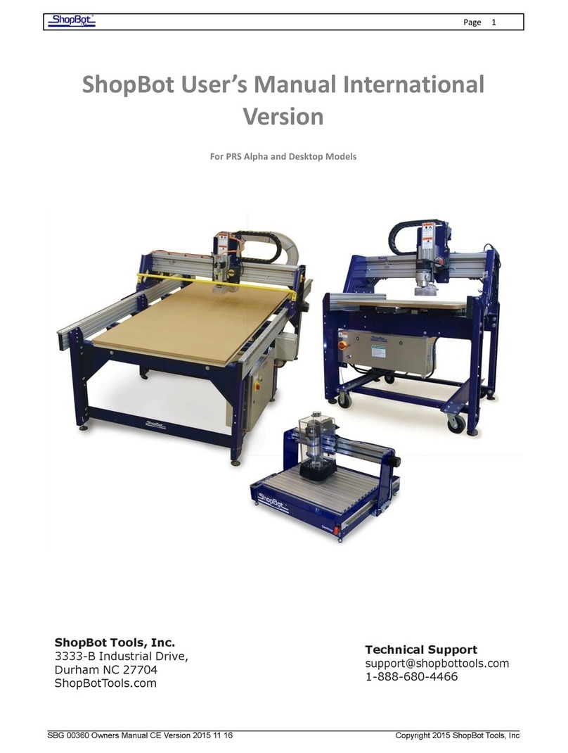
ShopBot PRS User manual

pg.
1
ShopBot PRS Gantry Tool
Table Assembly Guide
Intro
This guide will walk you through the mechanical assembly of your ShopBot PRS Gantry tool. It does
not include instructions for wiring, software training, troubleshooting, or maintenance. Additional
documentation is available at www.shopbotdocs.com.
Assemble Your Shopbot PRS Gantry Tool 2015 02 27.Docx © 2015 ShopBot Tools, Inc.

pg.
2
Table of Contents
Intro....................................................................................................................................................................... 1
Section 1: Before you start ..................................................................................................................................... 4
Tools and materials required:.............................................................................................................4
Frame assembly:............................................................................................................................................. 4
Mounting the table surface:............................................................................................................................ 4
Wiring the control box (this document does not provide wiring instructions, but it will be helpful to make sure
you have all your tools first):........................................................................................................................... 4
Electrical precautions .........................................................................................................................5
Overview of the ShopBot PRS CNC tool ..............................................................................................6
Terms to know................................................................................................................................................ 7
Major components: ........................................................................................................................................7
X/Y/Z axis and directions of travel ...................................................................................................................9
Section 2: Table assembly..................................................................................................................................... 10
Visual guide to table parts and hardware......................................................................................... 11
Attach hardware to the table Legs.................................................................................................... 12
Attach the legs to the table sides ..................................................................................................... 13
Attach the lower support ................................................................................................................. 14
Attach the first upper table support and gussets.............................................................................. 15
Slide the first cross-support into position......................................................................................... 17
Add the middle legs (This step is not needed if you are setting up a 48x48 or 60x48 table)............. 17
Add the final set of legs .................................................................................................................... 18
Level and square the table frame ..................................................................................................... 19
Level and square the front table side ............................................................................................................ 19
Level the rear table side................................................................................................................................ 21
Square the rear table side............................................................................................................................. 22
Mount the rails................................................................................................................................. 24
Place the gantry onto the rails.......................................................................................................... 25
Place the YZ car onto the gantry....................................................................................................... 27
Replace the lower wheels ............................................................................................................................. 27
Adjust the lower wheels................................................................................................................................ 28
Attach the rail wipers.................................................................................................................................... 29
Section 3: Mounting the motors and other peripherals......................................................................................... 30
Mount the motors ............................................................................................................................ 30
Secure the motor cables ................................................................................................................... 32
Mounting a router or spindle ........................................................................................................... 33
Router option ............................................................................................................................................... 33
Spindle option .............................................................................................................................................. 33
Mounting the VFD (Applies to spindles only. Skip this section if you are using a router). ................ 35
Determining the VFD Model.......................................................................................................................... 36
Mounting a 10” VFD...................................................................................................................................... 37
Mounting a 16” VFD...................................................................................................................................... 38
Connect power to your spindle......................................................................................................... 39
Assemble Your Shopbot PRS Gantry Tool 2015 02 27.Docx © 2015 ShopBot Tools, Inc.

pg.
3
Mount the mechanical end stops and proximity switches................................................................ 40
Mechanical end stops ................................................................................................................................... 40
Install the proximity switches........................................................................................................................ 41
Mount the Z zero plate assembly ..................................................................................................... 44
Install the Y axis E-chain ................................................................................................................... 45
Add wires to the Y axis E-chain...................................................................................................................... 48
Open the Y axis E-chain................................................................................................................................. 48
Cable management without an E-chain............................................................................................ 50
Install the X axis E-chain ................................................................................................................... 51
Install the X axis upper E-chain bracket ......................................................................................................... 52
Install the chain ............................................................................................................................................ 52
Install the dust skirt ................................................................................ Error! Bookmark not defined.
Connecting to the dust collection system ............................................... Error! Bookmark not defined.
Grounding the dust skirt......................................................................... Error! Bookmark not defined.
Mount the table surface (for non-vacuum tables)............................................................................ 53
Base layer..................................................................................................................................................... 53
Spoilboard .................................................................................................................................................... 54
Assemble Your Shopbot PRS Gantry Tool 2015 02 27.Docx © 2015 ShopBot Tools, Inc.

pg.
4
Section 1: Before you start
Tools and materials required:
Frame assembly:
•Framing square
•Level (6’ or longer is ideal)
•8’ straightedge (if using a shorter level)
•Tape measure
•Set of standard and metric allen wrenches
•Standard ratchet and socket set
•Adjustable wrench
•Flat wrench (included in box)
•Two “Quick Grip”-style clamps (recommended) or C-clamps
•Lightweight machine oil (available at any home improvement or auto supply store)
Mounting the table surface:
•Drill and standard-size bits
•1” Spade or Forstner drill bit
•1-1/2” wood screws
•One gallon of general-purpose wood glue
•Paint roller for spreading glue (recommended but not required)
•At least 2 sheets of material for your table surface:
•For 96x48 tables, you will need one sheet of Medium Density Fiberboard (MDF) and one
sheet of 3/4” cabinet-grade plywood. When choosing plywood, keep in mind that a higher
number of plys typically creates a more stable board that is less likely to warp (in other
words, don’t use cheap 5-ply utility sheathing!) Tables larger than 96x48 will require more
material per layer in order to cover the entire work area.
Note: If you are installing a vacuum table, please see the separate document titled “Installing a
Vacuum Hold-down system.” Your material requirements will be different from the ones listed here.
Wiring the control box (this document does not provide wiring instructions, but it will be helpful to
make sure you have all your tools first):
•Incoming power cable (please see the wiring diagram inside your control box for
specifications).
•Wire cutters and strippers
•Needle-nose pliers
•Standard sized Flat-head and Phillips-head screwdrivers
•Small (suitable for electronics) flat-head and Phillips-head screwdrivers
Assemble Your Shopbot PRS Gantry Tool 2015 02 27.Docx © 2015 ShopBot Tools, Inc.

pg.
5
Electrical precautions
WARNING: RISK OF ELECTRIC SHOCK
The control box needs to be connected to your electrical service by a licensed
electrician who has experience with industrial equipment. Please do not risk
personal injury or damage to your machine by having an unlicensed individual
perform this job.
Connecting the power to your control box can be done before or after you complete assembly of the
tool, but it is easiest to wait until the tool is set up in its final position. If you have purchased a high
frequency spindle and/or a vacuum blower, these will also need to be connected by your electrician.
Wiring diagrams and specifications are located inside the door of the control box.
There are a few other electrical precautions you should be aware of:
Motor connections: DO NOT connect or disconnect your motor cables while the control box is
powered on. This can damage or destroy the motors or drivers.
Induced currents: AVOID moving any axis by hand when the control box is powered off. If you must
push/pull an axis by hand, do so very slowly. Spinning the motors can generate an electric charge
and damage the drivers or other electronic components.
Static Discharges: Electronic circuits are very sensitive to static and power surges. Please have your
electrician follow all wiring and grounding instructions. Avoid doing any vacuuming around your
machine before it is properly grounded, as vacuums can generate a large amount of static electricity
that can damage the control box if the machine is not grounded.
Assemble Your Shopbot PRS Gantry Tool 2015 02 27.Docx © 2015 ShopBot Tools, Inc.

pg.
6
Overview of the ShopBot PRS CNC tool
We've pre-assembled many components of your machine to reduce the number of assembly steps.
In many places, bolts or hardware are loosely fit in place to show you their intended location, so
you’ll need to remove this hardware before fitting the corresponding component into place.
Use caution when lifting boxes and
assembled components out of the crate.
There are several assembly steps where
having an assistant will make things much
easier. In particular, you will need assistance
unpacking the crate and lifting the gantry
onto the table rails. Do not attempt to lift
the gantry without assistance.
Assemble Your Shopbot PRS Gantry Tool 2015 02 27.Docx © 2015 ShopBot Tools, Inc.

pg.
7
Major components:
Terms to know
Before you unpack the crate, let's go over the some of the major components and get familiar with
the terminology and directions we'll be using. This is only a quick overview to help get you started.
For each assembly section, there will be a visual guide with all parts and hardware clearly labeled.
The base of your machine is referred to as the
table frame.
The two long aluminum extrusions on each side
are called table sides, which create the path of
travel for the X-axis.
The table sides and related components are
included in the long cardboard package secured
to the top of your crate.
The assembly that rides along the table sides is
called the Gantry.
The gantry consists of an extruded aluminum
beam, which has been fitted with V-rails (for
wheel bearings) and gear rack. This forms the
path of travel for the Y axis.
The blue plates on either side of the gantry
are referred to as end plates.
The YZ car moves across the gantry, and also
controls the height of the cutter head (either
a router or high-speed spindle, depending on
your tool).
Assemble Your Shopbot PRS Gantry Tool 2015 02 27.Docx © 2015 ShopBot Tools, Inc.

pg.
8
VFD (For spindles only)
This controls speed and power for your
spindle. The control box provides the VFD
with on/off signals, but speed is controlled
through an RPM controller unit, which
connects to your PC through a separate USB
cable.
Control box
The control box is the “brain” of your
machine and contains a control board,
motor drivers, and numerous other
electronic components that allow the tool to
move with precision, accuracy, and power.
It connects to your PC through a single USB
cable.
Assemble Your Shopbot PRS Gantry Tool 2015 02 27.Docx © 2015 ShopBot Tools, Inc.

pg.
9
X/Y/Z axis and directions of travel
In all of our assembly and training instructions, we will frequently refer to the machine by each axis
so It will help to become familiar with them before you start. Another frequently-used term is the XY
home position, which is indicated here and on your table drawing at the back of this guide. For a
detailed explanation of your machine’s coordinate location system, please reference the full user’s
manual. For now, just make sure that you understand the directions of travel for the X, Y, and Z axis,
as well as where the XY home position is located.
Assemble Your Shopbot PRS Gantry Tool 2015 02 27.Docx © 2015 ShopBot Tools, Inc.

pg.
10
Section 2: Table assembly
Time to get started!
The diagrams in this manual depict a ShopBot with a “generic” 96x48 table. Depending on the size and shape of
your tool, the table layout may look a little different (fewer or more legs, different shape, etc.). For specific
dimensions, reference the table drawing included in the back of this assembly manual.
Please note: It is critical that you assemble your tool according to the measurements in the table
drawing.
Assemble Your Shopbot PRS Gantry Tool 2015 02 27.Docx © 2015 ShopBot Tools, Inc.

pg.
11
Visual guide to table parts and hardware
Except for the table levellers, all of this hardware is included in the small box marked “table
hardware”:
Assemble Your Shopbot PRS Gantry Tool 2015 02 27.Docx © 2015 ShopBot Tools, Inc.

pg.
12
Attach hardware to the table Legs
Screw a leg leveler into the bottom of each
Table Leg, then thread a 5/8” hex nut onto
the leg leveler. Leave this nut loose for now.
Assemble Your Shopbot PRS Gantry Tool 2015 02 27.Docx © 2015 ShopBot Tools, Inc.

pg.
13
Attach the legs to the table sides
Attach the first leg by sliding the T-nuts into
the T-slots on the table side. Place the leg
according to the table drawing in the back of
this guide and ensure T-nuts are lined up
with the holes. Place 5/16” hex bolts, lock
washers, flat washers and T-nuts into the
eight holes on each of the table legs, as
shown here.
Hold a framing square against the leg and
the extrusion while you tighten the bolts.
Repeat this process with the other table
side. You should have one leg on each table
side at this point. Next, temporarily attach a
second table leg to the outside of each table
side (this will allow you to slide the rest of
the components down the table sides
without the legs getting in the way). It
should look like the picture to the left.
Assemble Your Shopbot PRS Gantry Tool 2015 02 27.Docx © 2015 ShopBot Tools, Inc.

pg.
14
Attach the lower support
Use the same order of 1/2” hardware (hex
bolt and flat washer on one side—flat
washer, lock washer, and hex nut on the
back side) to secure the lower support to
the first set of table legs.
Assemble Your Shopbot PRS Gantry Tool 2015 02 27.Docx © 2015 ShopBot Tools, Inc.

pg.
15
Attach the first upper table support and gussets
Attach two 5/16” hex bolts, flat washers, and T-
nuts to each side of one of the upper supports.
Slide the T-nuts into the bottom channel of the
far end of the table side (where you have
temporarily mounted the legs on the outside of
the rails). Then slide this support all the way
down to the other pair of table legs, leaving
approximately 3/16” between the leg and the
upper cross support for the gussets.
Insert a gusset between each table leg and upper
support.
Attach this to the leg using 1/2” hardware (hex
bolt with a flat washer on one side and then a
flat washer, lock washer, and hex nut on other
side).
DO NOT fully tighten the bolts on the
upper support. You will need some
room for adjustment when you
square and level the table after
assembly.
Assemble Your Shopbot PRS Gantry Tool 2015 02 27.Docx © 2015 ShopBot Tools, Inc.

pg.
16
Your table should now look like this.
Assemble Your Shopbot PRS Gantry Tool 2015 02 27.Docx © 2015 ShopBot Tools, Inc.

pg.
17
Slide the first cross-support into position
Add the middle legs (This step is not needed if you are setting up a 48x48 or
60x48 table)
For the middle legs you will need to repeat some of the previous steps. First you will need to add a second upper
support. However, this support needs to be installed facing the opposite direction of the first one. The middle leg
will be “sandwiched” between two upper supports so keep that in mind during installation.
Next, add another cross-support. Reference the spacing from the middle leg according to your table drawing.
Complete the middle leg installation by attaching the lower support to either side of the middle leg pair.
Attach two 5/16” hardware assemblies ( 5/16”
hex bolt, lock washer, flat washer, and T-nut) to
each end of a cross-support beam.
Then slide the T-nuts into the bottom channels
of the table sides and slide the cross supports
into position.
For proper spacing of the cross supports, please
reference the table drawing in the back of this
manual (spacing will be different for each
model).
Remember, don’t fully tighten any of the
cross-supports yet.
Assemble Your Shopbot PRS Gantry Tool 2015 02 27.Docx © 2015 ShopBot Tools, Inc.

pg.
18
Add the final set of legs
Slide the last remaining upper support into place, then move the last two legs from the outside to the inside of the
table sides. Just like with the other legs, bolt the gussets and upper support to the leg, followed by the lower
support. Your table should now look like this:
Before moving on to the next step, check to make sure that you don’t have any leftover cross-supports or gussets.
We have included extra pieces of all your table hardware, so don’t be too concerned if you have a few extra nuts
and bolts left over.
Assemble Your Shopbot PRS Gantry Tool 2015 02 27.Docx © 2015 ShopBot Tools, Inc.

pg.
19
Level and square the table frame
Level and square the front table side
From this point on, we will refer to the table sides as front and rear. The front side of the table will
be closest to the 0,0 point as indicated on your table drawing. Using the longest level you have (6 or
8 feet is ideal), set the level on the front table side and adjust the leg levelers until this table side is
level. Do the main adjustments with the end legs, as the middle leg is primarily just there for support.
After those are level make sure that the center leg properly supports the beam and does not cause
the table side to bow or sag.
Assemble Your Shopbot PRS Gantry Tool 2015 02 27.Docx © 2015 ShopBot Tools, Inc.

pg.
20
Next, use a framing square to check that the first cross-support is square to the FRONT table side
only. Adjust if needed and then fully tighten the bolts on this side. Repeat this step with the next
cross support, until everything attached to the front table side is square.
Assemble Your Shopbot PRS Gantry Tool 2015 02 27.Docx © 2015 ShopBot Tools, Inc.
Table of contents
Other ShopBot Industrial Equipment manuals

