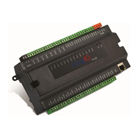
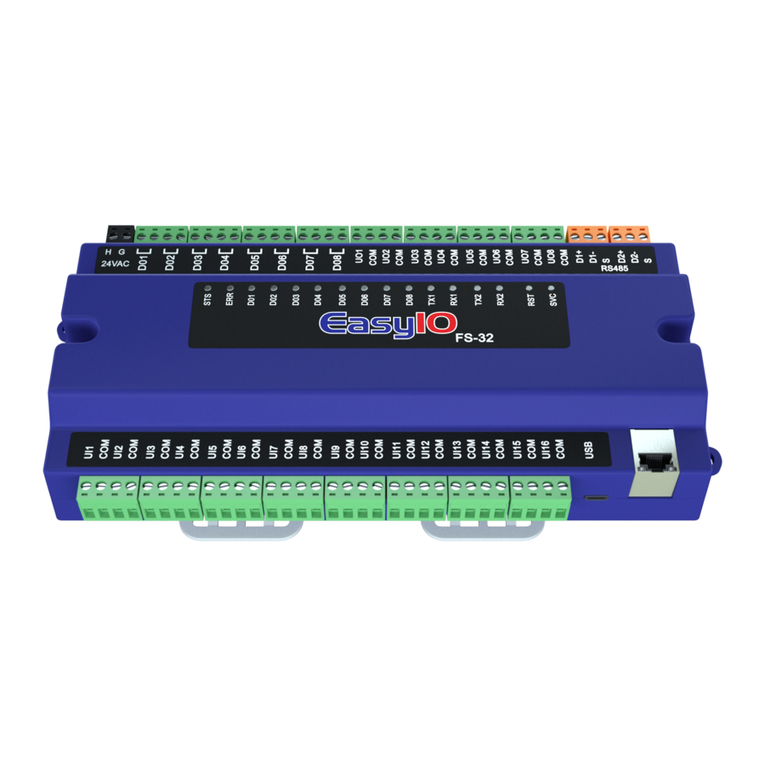
EasyIO FS Series User manual

FG Series Modbus Slave v1.0
1
EasyIO FS Series
Modbus Slave User Guide

FG Series Modbus Slave v1.0
2
Document Change Log
25th Dec 2019
Document created for FS Series ONLY.

FG Series Modbus Slave v1.0
3
Disclaimer
Confidentiality Notice
The information contained in this document is confidential information of EasyIO Holdings Pte Ltd. Such
information and the software described herein, is furnished under a license agreement and may be used
only in accordance with that agreement.
The information contained in this document is provided solely for use by EasyIO Holdings Pte Ltd employees,
licensees, and system owners; and, except as permitted under the below copyright notice, is not to be released to,
or reproduced for, anyone else.
While every effort has been made to assure the accuracy of this document, EasyIO Holdings Pte Ltd is not
responsible for damages of any kind, including without limitation consequential damages, arising from the
application of the information contained herein. Information and specifications published here are current as of
the date of this publication and are subject to change without notice. The latest product
specifications can be found by contacting our corporate headquarters or support channel.
Trademark Notice
EasyIO logo are registered trademarks of EasyIO Holdings Pte Ltd.
CPT Tool is by Online Tools Inc.
BACnet and ASHRAE are registered trademarks of American Society of Heating, Refrigerating and Air-
Conditioning Engineers. All other product names and services, mentioned in this publication, that are
known to be trademarks, registered trademarks, or service marks are the property of their respective
owners.
Copyright and Patent Notice
This document may not, in whole or in part, be copied, photocopied, reproduced, translated, or reduced
to any electronic medium or machine-readable form without prior written consent from EasyIO Holdings Pte Ltd
Copyright © 2019 EasyIO Holdings Pte Ltd. All rights reserved
Disclaimer
The material in this manual is for information purposes only. The contents and the product it
describes are subject to change without notice. EasyIO Holdings Pte Ltd makes no
representations or warranties with respect to this manual. In no event shall EasyIO Holdings Pte Ltd be liable for
any damages, direct or incidental, arising out of or related to the use of this manual.
EasyIO Holdings Pte Ltd
101, Cecil Street #09-07
Tong Eng Building
Singapore 069533
Worldwide and Asia Pacific Support : support@easyio.com
Americas Support : support@easyio.pro
Europe Support : support@easyio.eu

FG Series Modbus Slave v1.0
4
Federal Communication Commission Interference Statement
This equipment has been tested and found to comply with the limits for a Class B digital device, pursuant to Part 15
of the FCC Rules. These limits are designed to provide reasonable protection against harmful interference in a
residential installation. This equipment generates, uses, and can radiate radio frequency energy and, if not
installed and used in accordance with the instructions, may cause harmful interference to radio communications.
However, there is no guarantee that interference will not occur in a particular installation. If this equipment does
cause harmful interference to radio or television reception, which can be determined by turning the equipment off
and on, the user is encouraged to try to correct the interference by one or more of the following measures:
•Reorient or relocate the receiving antenna.
•Increase the separation between the equipment and receiver.
•Connect the equipment into an outlet on a circuit different from that to which the receiver is connected.
•Consult the dealer or an experienced radio/TV technician for help.
Caution: Any changes or modifications not expressly approved by the party responsible for compliance could void
the user's authority to operate this equipment.
FCC Caution
This device complies with Part 15 of the FCC Rules. Operation is subject to the following two conditions: (1) This
device may not cause harmful interference, and (2) this device must accept any interference received, including
interference that may cause undesired operation.
FCC Radiation Exposure Statement
This equipment complies with FCC radiation exposure limits set forth for an uncontrolled environment. This
equipment should be installed and operated with minimum distance 20cm between the radiator & your body.
RF Exposure: A distance of 20 cm shall be maintained between the antenna and users, and the transmitter module
may not be co-located with any other transmitter or antenna.

FG Series Modbus Slave v1.0
5
Table of Contents
Introduction ...................................................................................................................................................................6
Prerequisites ..................................................................................................................................................................6
Device Software Configuration Limitations FG+ and FS ................................................................................................6
Configuring the Modbus Serial Network .......................................................................................................................7
Configuring the Modbus TCP Slave Network...............................................................................................................11
Technical Support ........................................................................................................................................................14

FG Series Modbus Slave v1.0
6
Introduction
EasyIO FG Series and FS Series supports Modbus device using the Modbus Slave driver.
It is capable of handling the following Modbus slave protocols;
1. Modbus RTU Slave
2. Modbus TCP Slave
Prerequisites
1. CPT Tool dated 10th Oct 2018 or later. Latest CPT at the time of the document is 06th Dec 2019.
2. For FS Series running v3.0b51b or later firmware is the best.
Device Software Configuration Limitations FG+ and FS
Modbus RTU Slave/ Modbus TCP Slave
Max Network allowed
1 (of both drivers)
Max Discrete Point allowed
200 register address (total)
Max Coil Output allowed
200 register address(total)
Max Input Register allowed
200 register address, depending to data type.
Integer data type occupy 1 register address
Float data type occupy 2 register address
Long data type occupy 2 register address
Max Holding Register allowed
200 register address, depending to data type.
Integer data type occupy 1 register address
Float data type occupy 2 registers address
Long data type occupy 2 registers address
The FS series is capable of employing both Modbus Slave RTU and Modbus Slave TCP networks on the same device.
There is however register addressing limitations which need to be observed when both network drivers are used
on the same device.
For example, the coil address space in the FS series is shared by both the RTU and TCP networks. If a coil address is
used in the RTU network the same address cannot be used in the TCP network.
For example if an RTU network is created and uses the a coil address “0”, the TCP network cannot create a new coil
address “0” however it can “share” the value from the RTU network coil address and vice versa. If a new individual
coil address is required to be created the network (RTU or TCP) should employ the next available consecutive
unused DEVICE coil address irrespective of network type.

FG Series Modbus Slave v1.0
7
Configuring the Modbus Serial Network
The architecture of the driver is deployed as shown below in Step 2. The network object can be dropped anywhere
in the Sedona app tree. Our recommendation is to create a separate folder for each network, identified as you
require.
Network
Points
**Note**
In order to configure the Modbus driver, below kits needs to be installed (minimum requirement).
1. easyioFGMbSlave –1.0.45.51.16 or higher
2. easyioFGDriver - 1.0.45.51.3 or higher
3. easyioFGSerial –1.0.45.51.2 or higher
Step 1
Connect to the controller with CPT Tools.
Default login credentials are as below;
IP address : 192.168.10.12
Username : admin
Password :<no password>
Add the kits to the controller by navigating to manage kits and install easyioFGMbSlave and easyioFGDriver into
your controller.
Step 2
Double click the service folder. It will display the service folder objects.
If the SerialService object is not present in the folder, drag and drop the service object in to the service folder from
the easyioFGSerial kit library.

FG Series Modbus Slave v1.0
8
Step 3
Choose easyioFGMbSlave from Sedona Palette
Drag & drop the ModbusSlaveSerialNetwork into your App. The object can be dropped in the EasyIO folder or a
new folder can be created for the Serial Network Object.
In the example below, the object is dropped into a new folder named “Modbus”.
Step 4
Double click the object to access the property sheet.
Configuration of the RTU network parameters such as baud rate, parity etc is carried out here.
The device address on the serial networkis set in this property.
When complete and all serial network and operational parameters are entered correctly and complete enable the
network.
Please ensure the “D2” terminal set is used for the serial network connection and observe the correct polarity.
Step 5
Drop any Modbus “serial” register type object under the Network Object.
Note that the register object must be a child of (dropped below) the Network object. It is possible to create folders
below the Network Object to allow logical management of the register objects.

FG Series Modbus Slave v1.0
9
Step 6
Modbus registers supported is DECIMAL format register addresses.
HEX or Modbus addressing formats are not allowed and will not operate.
Step 7
By default all registers are set to the disabled mode Enable = false). You will need to enable each register object in
the application in order for the register to be discovered by other systems i.e. the Modbus Master.
Step 8
A maximum of 200 Input Register and Holding Register are available. The FG Series Modbus Serial Slave Network
supports 3 data types including the Integer, Float and Long data types.
Integer and Signed Integer uses 16bit data and is represented with 1 register address.
Float and Long occupy 32bit data and is represented with 2 register addresses.
See below example of setting the address.
Input/
Holding
Registers
Data Type
Precision
Remarks
Word
16 bit
16 bit Signed Integer Standard
Long
32 bit
32 Bit Signed Integer Standard
Float
32 bit
32 Bit Float Standard

FG Series Modbus Slave v1.0
10
Address Name Register Type
------- -------------------- --------------
1000 Set Point (Float type) floating point (2 registers)
1002 Duration (Long type) 32-bit data (2 registers)
1004 Count (Integer) 16-bit data (1 register)
1005 Delay (Signed Integer) 16-bit data (1 register)
Step 9
The Modbus register by itself does not export any value.
You will need to manually link a valid value to the Modbus register.
Below an example of exporting a temp value as Modbus register.

FG Series Modbus Slave v1.0
11
Configuring the Modbus TCP Slave Network
The architecture of the driver is deployed as below. The network object can be located anywhere in the Sedona
app tree. Our recommendation is to create a separate folder foreach network.
Network
Points
**Note**
In order to configure the Modbus Slave driver, below kits needs to be installed (minimum requirement).
1. easyioFGMbSlave –1.0.45.51.16 or higher
2. easyioFGDriver - 1.0.45.51.3 or higher
3. easyioFGSerial –1.0.45.51.2 or higher
Step 1
Connect to the controller with CPT Tool.
Default login credentials are as below;
IP address : 192.168.10.12
Username : admin
Password :<no password>
Add the kits to the controller by navigating to manage kits and install easyioFGMbSlave and easyioFGDriver into
your controller.
Step 2
Choose easyioFGMbSlave from Sedona Palette
Drag & drop the ModbusSlaveTCPNetwork into your App. The object can be anywhere in the EasyIO folder. The
object can be placed in a new folder as well.
In this case, the object is drop into a new folder named “Modbus”.

FG Series Modbus Slave v1.0
12
Step 3
Double click the object to get into the property sheet.
Enable the network.
Step 4
Drop any Modbus register type object under the Network Object.
Register object must be a child of the Network object. However folders in the Network object is possible for better
data management.
Input/
Holding
Registers
Data Type
Precision
Remarks
Word
16 bit
16 bit Signed Integer Standard
Long
32 bit
32 Bit Signed Integer Standard
Float
32 bit
32 Bit Float Standard

FG Series Modbus Slave v1.0
13
Step 5
Modbus registers supported is DECIMAL format register addresses.
HEX or Modbus addressing formats are not allowed and will not operate.
Step 6
By default all register are disable. You will need to enable it in order for the register to be discovered by other
system.
Step 7
Input Register and Holding Register comes with max 200 address. It support 3 data types Integer, Float and also
Long.
Integer and Signed Integer uses 16bit data and is represented with 1 register address.
Float and Long occupy 32bit data and is represented with 2 register addresses.
See below example of setting the address.
Address Name Register Type
------- -------------------- --------------
1000 Set Point (Float type) floating point (2 registers)
1002 Duration (Long type) 32-bit data (2 registers)
1004 Count (Integer) 16-bit data (1 register)
1005 Delay (Signed Integer) 16-bit data (1 register)
Step 8
The Modbus register by itself does not export any value.
You will need to manually link a valid value to the Modbus register.
Below an example of exporting a temp value as Modbus register.
Other manuals for FS Series
2
Table of contents
Other EasyIO Network Hardware manuals
Popular Network Hardware manuals by other brands

Garland
Garland P10GSFPBPFE user guide

Linksys
Linksys EFG120 - EtherFast Network Attached Storage NAS... Specifications

ThermoFisher Scientific
ThermoFisher Scientific DeviceLink Connect Configuration and Installation Instruction Guide

Cabletron Systems
Cabletron Systems SWPIM-E1 installation guide

GL Communications
GL Communications PacketExpert 10GX Quick Verification

Fortinet
Fortinet FortiLog-100 quick start guide