EasyIO EIO-55 Series User manual

EIO-55 PRODUCT MANUAL
BACnet or Modbus Touchscreen Thermostat
EIO-55-MOD
EIO-55-BAC
EIO-55-MOD-HUM
EIO-55-BAC-HUM

EIO-55
1
The EIO-55 series smart thermostats offer a modern flush mounted slim design look for heating or cooling control. The thermostats
can be used for various zones. All EIO-55 series thermostats have 3.5" backlit color touchscreen.
The MOD models have built-in Modbus RTU communications and the BAC models provide BACnet MSTP communications. The
thermostats can also be configured to be used as a lighting and/or air conditioning interface.
Features
•24VAC/DC Power Supply
•3.5" Inch Backlit Touchscreen Display
•BACnet or Modbus Communication Models
•Heating and/or Cooling Control
•Flush Mounting in the US, UK or EURO Wall Mounting Box
•Attractive Modern Designer Look
•Built-In Temperature Sensor
•Two Remote NTC10 Sensors; external control (alternatively
outside temp display) or floor sensor
•ECO, Off and Holiday Modes with Fabric Frost Protection
•24V 5A Switched Output Relay Rating
•Digital Input for Overrides
•±2% rH Relative Humidity Option
Model Type
Model
Description
Modbus 3.5" Touchscreen Thermostat, Non-Programmable,
24Vac/dc Power Supply, Non-UL
BACnet MSTP 3.5" Touchscreen Thermostat,
Non-Programmable, 24Vac/dc Power Supply, Non-UL
EIO-55-MOD
EIO-55-BAC
EIO-55-MOD-HUM or
EIO-55-BAC-HUM
Relative Humidity Option, +/-2%rH
Technical Data
Power Supply
Power supply
24VAC/DC -10%/+15% max. 80mA
Power Consumption:
At 24VDC max 80mA
Display
Touchscreen
3.5" Backlit Touchscreen, 320 x 480 pixels, 255K colors
Signal Outputs
Relay Output
1 x 5A (res) 24Vac/dc Relay, SPST
Signal Inputs
Built-In Sensor
0..50°C (32..122°F) ±0.5°C (±0.9°F ) @ 25°C (@77°F)
Resistive Inputs
2 x External NTC10K3A1 Sensor
Digital Input
1 x Digital Input, Volt-Free Contact, Impedance <1KOhm
Optional Sensing
Humidity (RH Option)
Characteristics
Range
0..100%rH
Accuracy
±2% rH (within 20..80% rh)
Communication
Modbus (-MOD models)
Protocol
Modbus RTU
Interface
RS485; maximum 63 devices
Addressing
1..247 via Touchscreen
Communication
9k6/19k2/38k4/57k6/76k8 Baud; Parity None/Even/Odd, 1 or
2 Stop Bits (adjustable through Touchscreen)
BACnet (-BAC models)
Protocol
BACnet MSTP
Interface
RS485; maximum 63 devices
MAC Addressing
1..127 via Touchscreen

EIO-55
2
Device ID
Default 651000 + MAC Address, Adjustable
Communication
9k6/19k2/38k4/57k6/76k8 Baud; Parity None/Even/Odd, 1 or
2 Stop Bits (adjustable through Touchscreen)
Connections
Terminal Connections (Relay
Solid and Stranded Cable
& Power Supply)
Maximum Size: Solid; 0.05-2.5mm2, Stranded: 0.05-1.50mm2
/ 14 to 30 AWG (UL)
Rising Clamp: Size 2.5 x 2.2mm
Terminal Connections (Low
Solid and Stranded Cable; 90° Angle for Wiring
Voltage Terminals)
Maximum Size: 0.05 to 1.5mm2(EN ISO) / 14 to 30 AWG (UL)
Rising Clamp: Size 2.5 x 1.9mm
Environmental Conditions
Operating
Temperature
0°C...+50°C (32..122°F)
Humidity
0...95%rh (non-cond.)
Standards
CE Conformity
CE Directive 2004/108/EC (EMC), 2006/95/EC (LVD)
EN61000-6-3: 2001 (Generic Emission)
EN61000-6-1: 2001 (Generic Immunity)
EN60730-1:2016 (Low Voltage)
EN6100-4-2/4/5/11 (ESD, Transient, Surges, Interruptions)
Degree of Protection
IP20
Housing
Housing Material
Polycarbonate Plastics, Self Extinguishing
Mounting
Wall or Junction Box Mounting
Dimensions
W88mm (3.46") x H112mm (4.41") x D43mm (1.68")
Flush: W88mm (3.46") x H112mm (4.41") x D14.5mm (0.57")
Weight
220g
Wiring Connections
24V Model Wiring
RLY OUT
24VAC 5A (resistive) / 30VDC 300W Rated Relay Output
RLY COM
24VAC 5A (resistive) / 30VDC 300W Rated Relay Common
0V
0V Supply
24V
24Vac/dc Supply
RI1 (External Sensor 1)
Remote NTC10 Temperature Sensor Input
RI2 (External Sensor 2)
Floor NTC10 Temperature Sensor Input (or Outside Sensor)
DI1
Volt-Free Digital Input Contact (Holiday etc Override)
A+
Modbus / BACnet MSTP RS485 A+ Connection
B-
Modbus / BACnet MSTP RS485 B- Connection
G0
0V Common (internally linked with 0V supply)
WARNING:Switch off the power before any wiring is carried out.

EIO-55
3
Typical Thermostat Home
Screens The images below illustrate the typical home screens on the EIO thermostats. The screen is touch
sensitive and shows the current status of the thermostat. Inside the red/blue/white ring the thermostat
shows the current target temperature. The intensity of the red/blue ring changes based on the
temperature differing from the target temperature.
The small circle indicates the current room temperature (and if enabled the floor temperature and/or
outside temperature, and/or relative humidity via a smooth transition effect).
In the Cleaning Mode the number inside the large circle indicates the remaining cleaning time. The
Boost icon changes to Cleaning icon and by pressing it the cleaning mode can be cancelled..
In the Holiday Mode the home screen shows the current ECO mode target temperature, and ECO
icon. By pressing the Holiday Mode Icon, the holiday can be cancelled anytime.
Touchscreen
The EIO room thermostat home screen has multiple touch sensitive areas that allow the thermostat
settings to be changed.
•
UP and DOWN arrows; to alter the current target temperature temporarily.
•
SMALL ACTION CIRCLE (that contains current room temperature etc.); allows access to FUR-
THER SETTINGS AND INFORMATION screen.
•
FUNCTION BASED ICON; in holiday mode shows the holiday icon from where the holiday mode
can be cancelled, in cleaning mode shows the cleaning icon from where the mode can be can-
celled; in BOOST mode shows the BOOST icon from where the output can be Boosted on; in
OFF mode shows the OFF icon where the OFF mode can be cancelled.
•
ECO icon; when ECO mode is on, the ECO mode can be cancelled from the button.
•
A/C ICON; when AC is enabled the AC can be enabled/disabled from this icon (systems only).
•
LIGHTS ICON; when LIGHTS are enabled, the lights can be enabled/disabled from this icon
(systems only)
•
UNIT ICON; the user can change between °C and °F for display
Touchscreen Backlight
Further Settings and
Information
The touchscreen backlight level can be adjusted through the maintenance mode. During the normal
operation after 30 seconds of inactivity, the touchscreen dims to the "stand-by" level set. If the
backlight level is set to 0, the screen backlight switches off.
By pressing the DIM icon when the screen is active the screen is immediately dimmed to the
"stand-by" level. Pressing the DIM icon when the device is in the "stand-by level", switches the
backlight OFF.
The screen backlight is automatically activated when it is touched.
NOTE: To enter FURTHER SETTINGS screen, press SMALL ACTION CIRCLE (temperature
display) on the home screen.
The FURTHER SETTINGS shows additional user settings options on the EIO thermostats:-
•
OFF icon to switch thermostat to OFF

EIO-55
4
•
LOCK icon is used to lock the thermostat. Number of different lock modes options exist.
•
HOLIDAY icon is used to switch the thermostat to holiday mode (ECO setpoint or Off Mode)
•
CLEANING icon is used to enable timed cleaning mode.
•
COG WHEEL icon allows entry to the maintenance mode.
The FURTHER SETTINGS screen is protected by the Staff Code. As default the Staff Code is disabled (0000). If activated, the user will
need to enter the Staff Code to enter the screen.
Temperature Displays
Room
70°F
.1
EIO thermostats show the measured temperatures inside the SMALL ACTION CIRCLE. The
enabled temperatures rotate in and out in a sequence.
Room temperature is always displayed on the ACTION CIRCLE. The room
temperature uses as default the built-in temperature sensor but can be configured
to use an external sensor connected to RI1. The description for the room
temperature can be changed via Room Text parameter in the configuration
pages.
Floor
68°F.7
Outside
62°F
.6
Floor Temperature is displayed on the ACTION CIRCLE if the MIN- MAX
operation has been selected for the RI2 input (underfloor minimum/maximum
control). The description for the floor temperature can be changed via Floor Text
parameter in the configuration pages.
Outside Temperature is displayed on the ACTION CIRCLE if RI1/RI2 has been
selected or if the Outside Temp Source parameter has been set to Network and
valid network value is sent to the thermostat. The description for the outside
temperature can be changed via Outside Text parameter in the configuration
pages. By changing the description the outside temperature display can be used
to indicate many other types of measurements.

EIO-55
5
Temperature Modes
The thermostat controls to the target temperature by switching the relay ON/OFF as required. The
control logic has hysteresis i.e. in the heating mode the temperature has to exceed the target setpoint
plus the hysteresis to switch the relay OFF to prevent fast on/offs. In cooling mode this operates in
reverse. The diagram below illustrates the temperature control operation.
The target temperature is typically adjusted by the user by pressing UP & DOWN buttons. The target
temperature is changed in different operating situations;
•COMFORT MODE; target temperature as adjusted by the user (or via the networked
system) and displayed on the screen
•ECONOMY MODE; target temperature switched to the ECONOMY setpoint
•OFF MODE; the thermostat is OFF, but FROST setpoint is active protecting the building
Centigrade to Fahrenheit
ECO Mode
EIO-55 Series has Fahrenheit to Celcius icons on the top
of the Home Screen. From this icon it is possible to change
the units by touching this icon.
This option is particularly useful in hospitality applications
where the client base is expected to be international.
NOTE: EIO-55 series has all configuration parameters
displayed in Fahrenheit only.
The thermostat is switched to ECO mode via network
or via digital input. The thermostat operates also in the ECO
mode when the Holiday mode has been activated.
In the ECO mode the thermostat controls to the ECO
heating/cooling setpoint and the current target setpoint is
displayed on the screen.
When in the ECO mode, the ECO mode can be cancelled by
pressing the ECO icon on the front screen. Last command
controls the thermostat state i.e if the thermostat has been
switched to ECO mode via a digital input or over the network, the
user can cancel the mode through the touchscreen.
OFF Mode
The thermostats can be switched to OFF mode via
the touchscreen, digital volt-free input (e.g. time
clock) or via the communication network (system
configuration). The thermostat switches also to OFF
mode when the cleaning mode has been activated.
In the OFF mode the current Frost Setpoint is
displayed as the target temperature.
When in OFF mode if room temperature drops below
the Frost Setpoint, the frost protection is activated,
the SNOWFLAKE icon is displayed on the screen
and the relay output is switched ON. When the
thermostat has been overridden to OFF mode via the
network, or a digital input transition, the user can
cancel the OFF mode by pressing the OFF icon.
Similarly, a networked thermostat driven to OFF
mode by the user can be overridden back to
COMFORT mode using the network master.
Boost
Holiday Mode
Cleaning Mode
The thermostat relay can be switched ON for a timed period by activating the BOOST function. The
BOOST overrides the automatic temperature control and switches the output ON. As default the boost
time is set to 0 (deactivated).
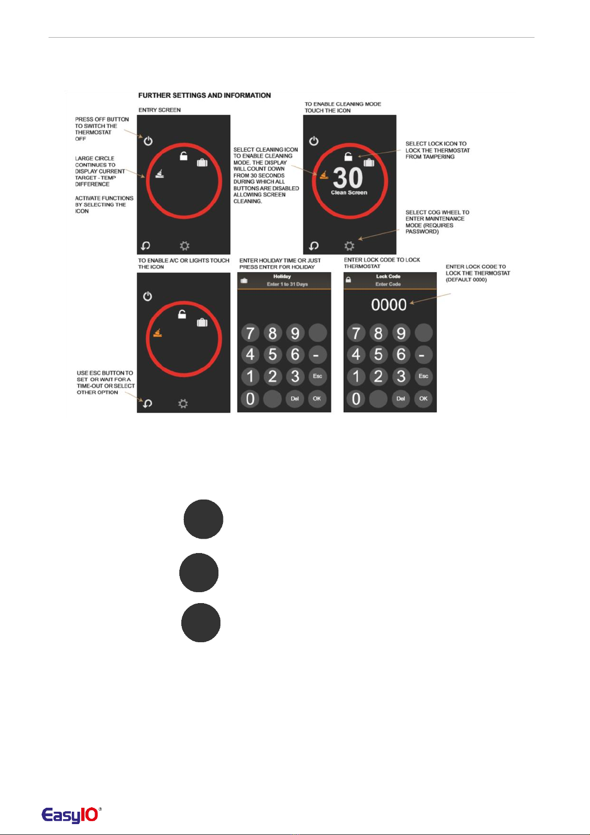
After entering FURTHER INFORMATION screen, by selecting the HOLIDAY icon, it is possible to set
the number of days of holidays. The available range is 0-31 days. After setting the holiday, the
thermostat immediately switches to OFF mode (alternatively EIO can switch to ECO MODE during
holidays, see configuration parameters).
By setting holiday to 0 or just by pressing ENTER button the thermostat switches to permanent
HOLIDAY MODE. The HOLIDAY MODE can be cancelled by pressing the HOLIDAY ICON.
After entering FURTHER INFORMATION screen, by selecting the CLEANING icon, it is possible to

EIO-55
6
activate the cleaning mode. Initially the thermostat will enter a "Clean Screen" state where all
touchscreen presses are ignored and 30 second countdown timer is displayed. This allows cleaning of
the thermostat itself.
Once the "Clean Screen" timeout has expired the thermostat enters a "Cleaning" state during
which control is automatically switched to the OFF/FROST mode and a countdown timer showing
the cleaning time remaining is displayed on the home screen. The cleaning period can be set to
0..480 minutes via Maintenance Mode. If the cleaning period is set to 0 (default) only the "Clean
Screen" function is applied.
A/C and Lights Enabled It is possible to enable A/C and LIGHTS buttons. The
buttons and their current status is displayed on the front screen.
The buttons are enabled through the Maintenance Mode in the
Display settings.
Note: These options will only switch corresponding network variable
on/off. The thermostat does not have any physical outputs to drive
A/C or Lights.
Lock Mode After entering FURTHER INFORMATION screen, by selecting the LOCK icon it is possible to lock the
thermostat. Now by entering the LOCK CODE, the thermostat lock state
can be activated.
The lock mode can be configured to work in different ways:
•DISABLED: Lock Mode Icon Not Available
•ON/OFF/BOOST ONLY: Allows On/Off/Boost Buttons Only
•ADJUST ONLY: Allows Temperature Adjustment, Or Optional
Lights/AC Buttons Only
•NO INPUT: All Buttons Locked
If the lock code is set to 0000 (default), there is no need to enter the lock
code and the lock code entry screen is bypassed.
Lock Mode Options
Icon Active
Lock
Up and
Boost / OFF
ECO /
AC
Lights
Down
Cleaning
DISABLED
NO
YES
YES
YES
YES
YES
ON/OFF ONLY
YES
NO
YES
NO
YES
YES
ADJUST ONLY
YES
YES
NO
NO
NO
NO
NO INPUT
YES
NO
NO
NO
NO
NO
Alarm Display When entering FURTHER
INFORMATION AND SETTINGS
screen and an alarm is active,
select the alarm icon for more
information.
The typical alarm reasons are:
•External sensor 1 (RI1) fault
(when activated; out of
range)
•External sensor 2 (RI2) fault
(when activated; out of
range)
•Internal sensor fault
•Digital Input Contact Fault
Alarm
External Sensor RI1 Input
A remote NTC10k3 sensor can be connected to this input to used for the temperature control and
monitoring purposes. The options are:-
•
DISABLED: RI1 is disabled.
•
CONTROL: RI1 is used for the temperature control.
•
OUTSIDE: RI1 is used to display (Outside) Temperature on the ACTION CIRCLE. It is possible
to change the text to indicate alternative measurement.
•
SYSTEM: RI1 is available over the communication network for system purposes.

EIO-55
7
External Sensor RI 2 Input
A remote NTC10k3 sensor can be connected to this input and can be configured for the following
(Underfloor/Outside Sensor )
functionality:-
•
DISABLED: RI2 is disabled.
•
MIN-MAX: RI2 is used for the underfloor minimum/maximum temperature limiting control.
•
OUTSIDE: RI2 is used to display (Outside) Temperature on the ACTION CIRCLE. It is possible
to change the text to indicate alternative measurement.
•
SYSTEM: RI2 is available over the communication network for system purposes.
Note: If both RI1 and RI2 inputs are set to outside, the RI2 input takes the precedence
Outside Temperature Source
It is possible to configure the thermostat to show the outside temperature from the External Sensor
inputs RI1 or RI2. In networked systems it is also possible to send the outside temperature from the
network by configuring the Outside Temp Source parameter as Network.
DI1 Digital Volt-Free Input The digital volt-free contact can be used to override the thermostat to ECO and OFF/FROST modes. The
configuration options are:
•Close for ECO Mode
•Open for ECO Mode
•Close for OFF/FROST Mode
•Open for OFF/FROST Mode
•Heating/Cooling (Change-Over Configuration)
•Alarm
•Network
"Close For" Configuration - The digital volt-free contact can be linked to e.g. external timer to switch the
thermostat to ECO/OFF mode during the timed period.
"Open For" Configuration - The digital volt-free input can be used to activate ECO or OFF mode when
the contact opens. In this mode it can be connected to a window switch or door card switch.
Heating/Cooling Change-Over Configuration - The digital input can be used to override from heating to
cooling mode. The thermostat works in the heating mode when the contact is open, and in the cooling
mode when the contact is closed.
Alarm Configuration - when the contact closes the "DI Contact Alarm" alarm message is displayed on the
screen.
Network option is selected when the digital input is used for monitoring purposes only.
Humidity Measurement and Display (-RH option)
The models with RH option have a 2%rH accurate humidity sensor for room space humidity
measurement. The humidity reading is displayed inside the SMALL ACTION CIRCLE (display as default
enabled, option to disable through configuration pages) and available over the communication network.
Underfloor Heating/Cooling Control
When underfloor high/low limit sensor is fitted, the thermostat monitors the floor temperature.
If in HEATING CONTROL in COMFORT/ECO/BOOST modes:
•The relay is switched OFF if the Max. Floor Temp Limit is exceeded
•The relay switches back ON if the floor temp drops 1.8°F (Hysteresis) below the Max Temp Limit
•The relay is switched ON if the Floor Temperature drops below the Min Floor Temp Limit. This override
is removed if the Floor Temperature exceeds 1.8°F the Min Floor Limit (Hysteresis)
This high limit is typically used to protect the floor surface. The minimum temperature limit is typically
used in bathrooms to provide minimum comfort level for bare feet and to dry up water.
If in COOLING CONTROL in COMFORT/ECO/BOOST modes:
•The relay is switched OFF if the temperature drops below the Min. Floor Temp Limit
•The relay switches ON with the temperature exceeds 1.8°F (hysteresis) above the Min Floor
Temp Limit
The low limit is typically used to prevent condensation.
The hysteresis is adjustable. To indicate the limit being active, the thermostat home screen shows a limit
icon next to setpoint.
Touchscreen Calibration The touchscreen can be re-calibrated by pressing the screen on power-up. Calibrate the screen by
swiping to the all four edges of the screen and then press OK to accept the new settings.
Language Selection ESRT55 user pages can be displayed in different languages by selecting the language from the
System Configuration pages.
Configuration Parameters

EIO-55
8
The EIO thermostats are configured to operate in different modes via the configuration parameters
accessible through the maintenance mode.
To enter the maintenance mode click the COG WHEEL icon in the FURTHER SETTINGS SCREEN
and enter the maintenance mode password (default 6666).
Note:
The maintenance mode password can be changed in the configuration settings. Make sure that
you note the new password if changed. If the Maintenance Code is set as 0000, the Maintenance
Code entry screen is bypassed (i.e. no protection).
CONTROL SETTINGS
Parameter Name
Description
Range
Nominal Setpoint
Nominal Setpoint
0.0...95.0 °F (Default 70.0°F)
ECO Heating Setpoint
ECO Mode Heating Setpoint
0.0...95.0 °F (Default 60.0°F)
ECO Cooling Setpoint
ECO Mode Cooling Setpoint
0.0...95.0 °F (Default 82.0°F)
Frost Setpoint
Night Frost Setpoint (OFF Mode)
0.0...95.0 °F (Default 46.0°F)
Min Setpoint Adj
Minimum Adjustable Setpoint
0.0...95.0 °F (Default 57.0 °F)
Max Setpoint Adj
Maximum Adjustable Setpoint
0.0...95.0 °F (Default 86.0 °F)
Hysteresis
Temperature Control Hysteresis
0.0..20.0 °F (Default 1.8°F)
Control Type
Heating and/or Cooling Control (change-over via
0 = Heating Control (default)
Digital input or over the communications network)
1 = Cooling Control
2 = Heating/Cooling Change-Over
Min Limit
Underfloor Heating Minimum Limit Setpoint
0.0...95.0 °F (Default 64.0°F)
Max Limit
Underfloor Heating Maximum Limit Setpoint
0.0...122.0 °F (Default 86.0°F)
Limit Hysteresis
Underfloor Heating Control Hysteresis
0.0..10.0 (default 1.8)
INPUTS
Parameter Name
Description
Range
RI1 Mode
Remote Temperature Sensor RI1 Mode
0 = Disabled (Default)
(status monitoring over the network is active for all
1 = Control
active modes)
2 = Outside Temperature (Display)
3 = Network (Networked Solutions)
RI2 Mode
Remote Temperature Sensor RI1 Mode
0 = Disabled (Default)
(status monitoring over the network is active for all
1 = Underfloor Min-Max Control
active modes)
2 = Outside Sensor (Display)
3 = Network (networked Solutions)
Digital Input Mode
Digital Input Operation
(status monitoring over the network is active for all
modes)
0 = Disabled (no EIO effect) 1
= Close for ECO
2 = Open for ECO
2 = Close for OFF/FROST
3 = Open for OFF/FROST
4 = Heating / Cooling Mode
5 = DI Contact Alarm
6 = Network
Digital Input Delay
Digital Input Delay Timer (transition from active to
0..7200 seconds (Default 0s)
non-active)
Outside Temp Source
Source for the Outside Temperature Display
0 = Built-In Sensor
1 = Network Sensor
Internal Sensor Cal
Internal Sensor One Point Compensation
-10.0..+10.0 °F
RI1 Cal
Sensor Connected to RI1 Calibration
-10.0..+10.0 °F
RI2 Cal
Sensor Connected to RI2 Calibration
-10.0..+10.0 °F
Humidity Cal
Humidity Calibration
-10.0..+10.0 % rH

EIO-55
9
OPERATING MODES
Parameter Name
Description
Range
Power Up
Power Up Operation
0
= Thermostat On when power
applied (default)
1
= Thermostat Off when power
applied
Lock Mode
Lock Operation
0
= Disabled (default)
1
= On/Off/Boost Workable Only
2
= Temp Adjust Only Available
3
= No Input - All Buttons Disabled
Lock Code
Lock Mode Password
0000 - 9999 (default 0000)
Cleaning Time
Cleaning Mode Running Time
0..480 minutes (Default 30)
Relay Mode
Select Relay Operation
0
= Normally Open (Default)
1
= Normally Closed
Boost Time
Boost Mode Running Time
0..480 minutes (Default 0)
0
= Disabled
Holiday Mode
Holiday Mode Override Target
0
= Off Mode (default)
DISPLAY
Parameter Name
Description
Range
Brightness
Backlight Brightness
0..20 (default 5)
Enable Lights
Enable Lights Icon / Network Variable
0
= Disabled (default)
1
= Enabled
Enable AC
Enable AC Icon / Network Variable
0
= Disabled (default)
1
= Enabled
Enable Holiday
Enable Holiday Icon
0
= Disabled
1
= Enabled (default)
Humidity Display
Enable / Disable Humidity Display (if option fitted)
0
= Disabled
1
= Enabled (default)
Show Unit Swap
Enable Temperature Display Unit Selection Button
0
= Disabled
(°C/°F)
1
= Enabled (default)
Zone 1 Text
Description for the Room Sensor (Built-In Sensor /
1
= Room (Default)
RI1)
2
= Floor
3
= Outside
4
= Zone 1
5
= Zone 2
6
= Zone 3
7
= Bathroom
8
= Sauna
9
= Bedroom
10 = Kitchen
11 = Cooler
12 = Flow
13 = Hot Water
14 = Tank
15 = Pool
DISPLAY
Parameter Name
Description
Range
Zone 2 Text
Description for the Floor Sensor (RI2)
0
= Disabled
Default; 2 = Floor
1
= Room
Note: Disabled removes Floor Text and
2
= Floor
Measurement from Display
3
= Outside
Zone 3 Text
Description for the Outside Sensor (RI1 / RI2 /
4
= Zone 1
5
= Zone 2
Network Value)
6
= Zone 3
Default; 3 = Outside
7
= Bathroom
Note: Disabled removes Outside Text and
8
= Sauna
Measurement from Display
9
= Bedroom
10 = Kitchen
11 = Cooler
12 = Flow
13 = Hot Water
14 = Tank
15 = Pool

EIO-55
10
SYSTEM
Parameter Name
Description
Range
Address
Modbus Address (Only Modbus versions)
0..247 (Default 1)
BACnet MAC Address (Only BACnet versions)
0..127 (Default 1)
Baud Rate (Only Modbus/BACnet versions)
Modbus / BACnet Baud Rate
0
= 9600 (Default)
1
= 19200
2
= 38400
3
= 57600
4
= 76800
Parity (Only Modbus/BACnet versions)
Parity
0
= None (Default)
1
= Odd
2
= Even
Stop Bits (Only Modbus/BACnet versions)
Stop Bits
0
= 1 Stop Bit (Default)
1
= 2 Stop Bits
Device ID (Only BACnet versions)
BACnet Device ID
0..4,194,303
(Default Auto=651001)
Service Pin (Only BACnet versions)
Bacnet Service Pin (when activated the device
0
= Disabled (default)
sends BACnet I-AM message)
1
= Enabled
Maintenance Code
Maintenance Mode Password
0000 - 9999 (default 6666)
Staff Code
Staff Page Password - Access Password to Further
0000 - 9999 (default 0000 =
Settings Screen
disabled)
Language
Default Language for User Screens
0
= English (Default)
1
= Finnish
2
= Swedish
Reload Default
Reload Factory Default Settings
0
= Off (default)
1
= On
Version
Software Version
x.xx (Modbus/BACnet)
NOTE: If the communication settings have been changed, they are activated upon exiting the Maintenance Mode - the device
carries out a soft reset. Alternatively, power cycle will activate the new communication settings
Parameter Storage
The configuration parameters are stored in the non-volatile memory. When the changes are carried out via the display, the parameters
are stored in the non- volatile memory when the controller returns to a normal display mode. If the changes are carried out over the
network (Modbus or BACnet), then "NonVol Update" register/object is required to be forced on to save the changes. The register will
automatically return to normal state when using Modbus. In BACnet the object needs to re-triggered.
Modbus Registers
The controller supports the following Modbus registers and function codes. The default communication speed is 9600 bps, 8 data bits,
Parity None and 1 Stop Bit. The default Modbus Slave address is 1. The device Parity can be changed between Odd, None and Even.
The baud rate is selectable between 9600, 19200, 38400, 57600 and 76800 bps. The table shows the register offsets starting from 0 (0
Base) register address. For example, the Temperature is read from Modbus register 100 using Function Code 04. Some Modbus
masters will require one to be added to Modbus registers (i.e. 1 Base). In this case Function Code 04, register 101 needs to be entered.
Register
Parameter Description
Data Type
Raw Data
Range
FUNCTION CODE 01 - READ COILS
FUNCTION CODE 05 - WRITE SINGLE COIL
FUNCTION CODE 15 - WRITE MULTIPLE COILS
100
Off Mode Override
0..1
Off - On
101
ECO Mode Override
0..1
Off - On
102
Heating/Cooling Mode (change-over mode)
0..1
0 = Heating, 1 = Cooling
FUNCTION CODE 02 - READ DISCRETE INPUTS
100
Digital Input Status
0..1
Off - On
101
Relay Output Status
0..1
Off - On
102
Holiday Mode Status
0..1
Off - On
103
Light Switch Status
0..1
Off - On
104
A/C Switch Status
0..1
Off - On
105
Cleaning Mode Status
0..1
Off - On
106
Screen Lock Status
0..1
Off - On
107
Boost Status
0..1
Off - On
108
ECO Mode Status
0..1
Off - On
109
Frost Status
0..1
Off - On
FUNCTION CODE 04 - READ INPUT REGISTERS
100
Built-In Temperature Measurement
Signed 16
-400...3020
-40.0...150.0°C

EIO-55
11
(-40.0..302.0°F)
101
External Temperature Measurement (Resistive
Signed 16
-400...3020
-40.0...150.0°C
Input 1)
(-40.0..302.0°F)
102
Underfloor Temperature Measurement
Signed 16
-400...3020
-40.0...150.0°C
(Resistive Input 2)
(-40.0..302.0°F)
103
Current Calculated Setpoint (°C)
Signed 16
-400...3020
-40.0...150.0°C
(-40.0..302.0°F)
104
Thermostat Current Mode
Unsigned 16
0..3
0 = Comfort
1 = ECO
2 = Frost
3 = Boost
105
Relative Humidity Measurement (with RH
Unsigned 16
0..1000
0..100.0 %rH
option)
106
Alarm State
Unsigned 16
0..256
Bit 0 - Interal NTC
Bit 1 - RI1
Bit 2 - RI2
Bit 3 - Humidity Sensor
Bit 4 - DI1
Bit 5 - DI2 (Not Applicable)
Bit 6 - Time Lost
107
Discrete Input Registers (Bit 0 = DI1, Bit1 =
Unsigned 16
0..65,535
N/A
Relay, Bit 2 = Holiday etc.)
200
Firmware Version
Unsigned 16
N/A
N/A
FUNCTION CODE 03 - READ HOLDING REGISTERS
FUNCTION CODE 06 - WRITE SINGLE HOLDING REGISTER
FUNCTION CODE 16 - WRITE MULTIPLE HOLDING REGISTERS
100
Nominal Setpoint
Unsigned 16
0...950
0.0...95.0 °F (Default 70.0°F)
101
ECO Heating Setpoint
Unsigned 16
0...950
0.0...95.0 °F (Default 60.0°F)
102
ECO Cooling Setpoint
Unsigned 16
0...950
0.0...95.0 °F (Default 82.0°F)
103
Frost Setpoint
Unsigned 16
0...950
0.0...95.0 °F (Default 64.0°F)
Register
Parameter Description
Data Type
Raw Data
Range
104
Minimum Setpoint
Unsigned 16
0...950
0.0...95.0 °F (Default 57.0 °F)
105
Maximum Setpoint
Unsigned 16
0...950
0.0...95.0 °F (Default 86.0 °F)
106
Hysteresis
Unsigned 16
0..200
0.0..20.0 °F (Default 1.8°F)
107
Rin1 Remote Temperature Sensor Mode
Unsigned 16
0..3
0
= Disabled (Default)
1
= Main Temperature Control
2
= Outdoor Temperature (Display)
3
= System (networked solutions)
108
Rin2 Underfloor Temperature Sensor Mode
Unsigned 16
0..3
0
= Disabled (default)
1
= Min-Max Control
2
= Outdoor Sensor
3
= System (networked solutions)
109
Control Type
Unsigned 16
0..2
0
= Heating Control (default)
1
= Cooling Control
2
= Heating/Cooling Change-Over
110
Min Floor Temp Limit
Unsigned 16
0...950
0.0...95.0°F (Default 64.0°F)
111
Max Floor Temp Limit
Unsigned 16
0...1220
0.0...122.0°F (Default 86.0°F)
112
Floor Limit Hysteresis
Unsigned 16
0...100
0.0..10.0 (default 1.8)
113
Digital Input Mode
Unsigned 16
0..7
0
= Disabled
1
= Close for ECO (Default)
2
= Open for ECO
3
= Close for OFF/FROST
4
= Open for OFF/FROST
5
= Heating / Cooling Mode
6
= Digital Input Alarm
7
= Network
114
Digital Input Delay
Unsigned 16
0..7200
0..7200 seconds (Default 0s)
115
Enable Lights Symbol
Unsigned 16
0..1
0
= Disabled (default)
1
= Enabled
116
Enable AC Symbol
Unsigned 16
0..1
0
= Disabled (default)
1
= Enabled
117
Power Up
Unsigned 16
0..1
0
= Thermostat On when power

EIO-55
12
applied (default)
1
= Thermostat Off when power
applied
118
Lock Mode
Unsigned 16
0..3
0
= Lock mode disabled (default)
1
= On/Off/Boost workable only
2
= Temp settings only available
3
= All buttons disabled
119
Enable Temperature Units Swap
Unsigned 16
0..1
0
= Disabled
1
= Enabled (Default)
120
Sensor Calibration
Signed 16
-100..+100
-10.0..+10.0 °F
121
RI1 Sensor Calibration
Signed 16
-100..+100
-10.0..+10.0 °F
122
RI2 Sensor Calibration
Signed 16
-100..+100
-10.0..+10.0 °F
123
Humidity Sensor Calibration
Signed 16
-100..+100
-10.0..+10.0 %rH
124
Humidity Display
Unsigned 16
0..1
0
= Disabled
1
= Enabled (default)
125
Cleaning Mode Time
Unsigned 16
0...480
0..480 minutes (Default 0)
126
Boost Mode Time
Unsigned 16
0...480
0..480 minutes (Default 0)
0
= Disabled
127
Backlight
Unsigned 16
1..20
0..20 (default 5)
128
Relay Control Mode
Unsigned 16
0..1
0
= Normally Open (Default)
1
= Normally Closed
129
Lock Mode Password
Unsigned 16
0..9999
0000...9999
130
Maintenance Mode Password
Unsigned 16
0..9999
0000...9999
131
Override A/C
Unsigned 16
0..2
0
= None (default)
1
= Override On
2
= Override Off
132
Override Lights
Unsigned 16
0..2
0
= None (default)
1
= Override On
2
= Override Off
133
Override Lock Mode
Unsigned 16
0..2
0
= None (default)
1
= Lock Screen
2
= Cancel Lock Mode
Register
Parameter Description
Data Type
Raw Data
Range
134
Enable Holiday Symbol
Unsigned 16
0..1
0
= Disabled
1
= Enabled (default)
135
Holiday Mode Target
Unsigned 16
0..1
0
= OFF/Frost Mode (default)
1
= ECO Mode
136
Relay Network Override (Overrides the relay
Unsigned 16
0..2
0
= No Override (Default)
drive directly)
1
= Override Relay On
2
= Override Relay Off
137
Staff Code
Unsigned 16
0..9999
0000...9999
138
Language
Unsigned 16
0..2
0 = English (Default)
1
= Finnish
2
= Swedish
139
Zone 1Text (Room Sensor Description)
Unsigned 16
1..15
1 = Room (Default)
2
= Floor
3
= Outside
4
= Zone 1
5
= Zone 2
6
= Zone 3
7
= Bathroom
8
= Sauna
9
= Bedroom
10 = Kitchen
11 = Cooler
12 = Flow
13 = Hot Water
14 = Tank
15 = Pool
140
Zone 2 Text (Floor Sensor Description)
Unsigned 16
0..15
0 = Disabled
Default: 2 = Floor
1
= Room
Note: Disabled removes the text and the
2
= Floor
Floor measurement from the display.
3
= Outside
141
Zone 3 Text (Outside / Network Sensor
Unsigned 16
0..15
4
= Zone 1
5
= Zone 2
Description)
6
= Zone 3
Default: 3 = Outside
7
= Bathroom
Note: Disabled removes the text and the
8
= Sauna
Floor measurement from the display.
9
= Bedroom
10 = Kitchen

EIO-55
13
11 = Cooler
12 = Flow
13 = Hot Water
14 = Tank
15 = Pool
142
Outside Temperature Source
Unsigned 16
0..1
0 = Buillt-In Sensor (Default)
1
= Network Sensor
143
Outside Air Temperature - Network Write
Signed 16
-580...1220
-58.0...122.0 °F (Default 0.0)
300
Modbus Address
Unsigned 16
0..247
0..247
(Default 1)
301
Modbus Baud Rate
Unsigned 16
0..4
0
= 9600 (Default)
1
= 19200
2
= 38400
3
= 57600
4
= 76800
302
Modbus Parity
Unsigned 16
0..2
0
= None (Default)
1
= Odd
2
= Even
303
Stop Bits
Unsigned 16
0...1
0
= 1 Stop Bit (Default)
1
= 2 Stop Bits
400
Force Reset
Unsigned 16
0..1
0
= Normal
1
= Force Reset
401
Non Volatile Memory Update
Unsigned 16
0..1
0
= Normal
1
= Update
403
Force Factory Defaults
Unsigned 16
0..1
0
= Normal
1
= Force Factory Defaults
Legacy Modbus Registers
The below Modbus registers are duplicate registers for legacy product support.
Register
Parameter Description
Data Type
Raw Data
Range
FUNCTION CODE 01 - READ COILS
FUNCTION CODE 05 - WRITE SINGLE COIL
3
Relay Output (Read Only, Relay Mode=Control)
0..1
Off - On
Relay Output Override (Relay Mode=Network)
FUNCTION CODE 04 - READ INPUT REGISTERS
0
Built-In Temperature Measurement
Signed 16
-400...3020
-40.0...150.0°C
(-40.0..302.0°F)
1
Underfloor Temperature Measurement
Signed 16
-400...3020
-40.0...150.0°C
(Resistive Input 2)
(-40.0..302.0°F)
FUNCTION CODE 03 - READ HOLDING REGISTERS
FUNCTION CODE 06 - WRITE SINGLE HOLDING REGISTER
FUNCTION CODE 16 - WRITE MULTIPLE HOLDING REGISTERS
1
Unit Status. Reports Day/ECO status. Can be
Unsigned 16
0..1
0 = Day
used to override to ECO. Reset locally.
1 = Night ECO Mode
2
Nominal Setpoint
Unsigned 16
0...950
0.0...95.0 °F (Default 70°F)
14
Minimum Setpoint
Unsigned 16
0...950
0.0...95.0°F (Default 57°F)
15
Maximum Setpoint
Unsigned 16
0...950
0.0...95.0°F (Default 86°F)
16
Hysteresis
Unsigned 16
0..200
0.0..20.0°F (Default 1.8°F)
18
Frost Setpoint
Unsigned 16
0...950
0.0...95.0°F (Default 46°F)
19
Modbus Address
Unsigned 16
0..247
0..247 (Default 1)
BACnet Interoperability
Building Blocks Supported
(Annex K)
Application Service
Initiate
Execute
BIBB
ReadProperty
Yes
DS-RP-B
ReadPropertyMultiple
Yes
DS-RPM-B
WriteProperty
Yes
DS-WP-B
ReinitializeDevice
Yes
Who-Is
Yes
DM-DDB-B
I-Am
Yes
Who-Has
Yes
DM-DOB-B
I-Have
Yes

EIO-55
14
DeviceCommunicationControl
Yes
DM-DCC-B
BACnet Standard Object
No dynamic Creation or Deletion supported. Objects, and object instances, are assigned to fixed
Types Supported
functions within the proprietary control application of the product as follows
Object
Number Of
Instance Assignments
Instances
Device Object
1
Analog Input
7
AI(0) –Room Temperature
AI(1) - Outside Temperature
AI(2) - Floor Temperature
AI(3) - Current Active Setpoint
AI(4) - Humidity Measurement
AI(5) –RI1 External Sensor 1
AI(6) –RI2 External Sensor 2
Analogue Value
13
AV(0) –Not Applicable (Target SP1)
AV(1) –Not Applicable (Target SP2)
AV(2) –Not Applicable (Target SP3)
AV(3) –Not Applicable (Target SP4)
AV(4) –ECO Heating Setpoint
AV(5) –ECO Cooling Setpoint
AV(6) –Frost Setpoint
AV(7) –Min Floor Limit
AV(8) –Max Floor Limit
AV(9) –LCD Brightness
AV(10) - Control Hysteresis
AV(11) - Network Temp
AV(12) - Nominal Setpoint
Binary Input
3
BI(0) –Digital Input (DI1)
BI(1) –Cleaning Mode Status
BI(2) –Boost Mode Status
Binary Output
9
BO(0) –Relay Output
BO(1) - OFF Mode
BO(2) - ECO Mode
BO(3) –Light Switch Status
BO(4) –AC Switch Status
BO(5) –Lock Screen
BO(6) –Heating/Cooling Change-Over
BO(7) - Non Volatile Update (updates
setpoints/configuration parameters)
BO(8) - Not Applicable (Hold)
MutliState Input
2
MSI(0) - Device Mode (1=Comfort,
2=ECO, 3=OFF)
MSI(1) - Alarm
Device Object Properties
Property Name /ID
Attributes
Range
Default
Object Identifier
R/W
20
Object Name
R/W
32 Characters Max
Concatenation of product type and MAC
address i.e. "ESRT001"
Object Type
R
Device
System Status
R
STATUS_OPERATIONAL
Vendor Identifier
651
Model Name
R
ESRT5
Protocol Version
R
1
Protocol Revision
R
10
Max APDU Length
R
480
Segmentation Support
R
No
APDU Timeout
R
6000 ms
Number APDU Retries
R
3
MaxMaster
R
127
Max_Info_Frames
R
1
Database Revision
R
0

EIO-55
15
App_Config Object
NOTE: Application Configuration Object exposes the configuration parameters over the
BACnet. However please check if your BACnet client can support Proprietary Object types to
be able to access these parameters. Alternatively set the configuration parameters through
the EIO touchscreen.
Property Name /ID
Attributes
Range
Default
Required
Object Identifier
R
proprietary-128
Object
Object Name
R/W
"App_Config"
Properties
Object Type
R
proprietary-128
Optional
None
Properties
Property ID
Description
BACnet Data Type
Range
Proprietary
30106
Alarm State
Unsigned
0 = No Fault
Properties
1
= Internal sensor fault
2
= RI1 fault
3
= Internal sensor & RI fault
4
= RI2 fault
5
= Internal Sensor & RI2 fault
6
= RI1 & RI2 fault
7
= Internal sensor, RI1 & RI2 Fault
40101
ECO Heating Setpoint
REAL
0.0...95.0 °F (Default 60.0°F)
40102
ECO Cooling Setpoint
REAL
0.0...95.0 °F (Default 82.0°F)
40103
Frost Setpoint
REAL
0.0...95.0 °F (Default 46.0°F)
40104
Minimum Setpoint
REAL
0.0...95.0 °F (Default 57.0 °F)
40105
Maximum Setpoint
REAL
0.0...95.0 °F (Default 86.0 °F)
40106
Hysteresis
REAL
0.0..20.0 °F (Default 1.8°F)
40107
Rin1 Remote Temperature Sensor
Unsigned
0 = Disabled (Default)
Mode
1
= Main Control
2
= Outdoor Temperature (Display)
3
= System (Networked Solutions)
40108
Rin2 Underfloor Temperature
Unsigned
0 = Disabled (default)
Sensor Mode
1
= Min-Max Control
2
= Outdoor Sensor
3
= System (Networked Solutions)
40109
Control Type
Unsigned
0 = Heating Control (default)
1
= Cooling Control
2
= Heating/Cooling Change-Over
40110
Min Floor Temp Limit
REAL
0.0...95.0°F (Default 64.0°F)
40111
Max Floor Temp Limit
REAL
0.0...122.0°F (Default 86.0°F)
40012
Floor Hysteresis
REAL
0.0..10.0 (default 1.8)
40113
Digital Input Mode
Unsigned
0 = Disabled
1
= Close for ECO (Default)
2
= Open for ECO
3
= Close for OFF/FROST
4
= Open for OFF/FROST
5
= Heating / Cooling Mode
6
= Digital Input Alarm
7
= Network
40114
Digital Input Delay
Unsigned
0..7200 seconds (Default 0s)
40115
Enable Lights Symbol
Unsigned
0 = Disabled (default)
1
= Enabled
40116
Enable AC Symbol
Unsigned
0 = Disabled (default)
1
= Enabled
40117
Power Up
Unsigned
0 = Thermostat On when power applied
(default)
1
= Thermostat Off when power applied
40118
Lock Mode
Unsigned
1 = Lock mode disabled (default)
2
= On/Off/Boost workable only
3
= Temp settings only available
4
= All buttons disabled (no input)
40119
Temperature Unit Swap Icon
Unsigned
0 = Disabled
1
= Enabled (default)
40121
RI1 Sensor Calibration
REAL
-10.0..+10.0 °F
40122
RI2 Sensor Calibration
REAL
-10.0..+10.0 °F

EIO-55
16
40123
Humidity Sensor Calibration
REAL
-10.0..+10.0 °F
40124
Humidity Display
Unsigned
0
= Disabled
1
= Enabled (default)
40125
Cleaning Mode Time
Unsigned
0..480 minutes (Default 0)
40126
Boost Mode Time
Unsigned
0..480 minutes (Default 0)
40127
Backlight
Unsigned
0..20 (default 5)
40128
Relay Control Mode
Unsigned
0
= Normally Open (Default)
1
= Normally Closed
40129
Lock Mode Password
Unsigned
0000...9999 (Default 0000)
40130
Maintenance Mode Password
Unsigned
0000...9999 (Default 6666)
40134
Enable Holiday Symbol
Unsigned
0
= Disabled
1
= Enabled (Default)
40135
Holiday Mode Target
Unsigned
0
= OFF/Frost Mode (Default)
1
= ECO Mode
40137
Staff Access Code
Unsigned
0000...9999
40138
Language
Unsigned
0
= English
1
= Finnish
2
= Swedish
40139
Zone 1 Text (Room Sensor
Unsigned
1
= Room (Default)
Description)
2
= Floor
3
= Outside
4
= Zone 1
5
= Zone 2
6
= Zone 3
7
= Bathroom
8
= Sauna
9
= Bedroom
10 = Kitchen
11 = Cooler
12 = Flow
13 = Hot Water
14 = Tank
15 = Pool
40140
Zone 2 Text (Floor Sensor
Unsigned
0
= Disabled
Description)
1
= Room
Default: 2 = Floor
2
= Floor
Note: Disabled removes the text
3
= Outside
and the Floor measurement from
4
= Zone 1
the display.
5
= Zone 2
40141
Zone 3 Text (Outside / Network
Unsigned
6
= Zone 3
7
= Bathroom
Sensor Description)
8
= Sauna
Default: 3 = Outside
9
= Bedroom
10 = Kitchen
11 = Cooler
12 = Flow
13 = Hot Water
14 = Tank
15 = Pool
40142
Outside Temperature Source
Unsigned
0
= Internal Sensor (Default)
1
= Network Temperature
40300
MAC Address
Unsigned
0..127 (Default 1)
40301
BACnet Baud Rate
Unsigned
0
= 9600 (Default)
1
= 19200
2
= 38400
3
= 57600
4
= 76800
40400
Force Reset
Unsigned
0
= Normal (Default)
1
= Force Reset
40401
Non Volatile Memory Update
Unsigned
0
= Normal
1
= Update
40403
Force Factory Defaults
Unsigned
0
= Normal (Default)
1
= Force Factory Defaults
This manual suits for next models
4
Table of contents
Other EasyIO Thermostat manuals
Popular Thermostat manuals by other brands

Siemens
Siemens RAA Series Technical instructions

Tactical
Tactical EBMST instruction manual

Systems Controls & Instruments
Systems Controls & Instruments CEM-24 Series owner's manual

Emerson
Emerson White-Rodgers 1F75H-21PR Installation and operating instructions

Honeywell
Honeywell T8131A owner's guide

Imit
Imit TA3 instruction manual