EASYSKY Micro B-17 Flying Fortress User manual

B-
17 Flying

2
● Assembled Micro B-17 Flying Fortress
● LiPo battery
● Transmitter
● Charging box
● Charging cable
● 4*AA batteries
Your Micro B-17 Flying Fortress should not be considered a toy, but rather a sophisticated, working model that
functions very much like a full-size airplane. Because of its performance capabilities, the Micro B-17 Flying
Fortress, if not assembled and operated correctly, could possibly cause injury to yourself or spectators and
damage to property.
1. Operate the plane according to the instructions. DO NOT alter or modify the model. If you make any
modifications, you void your warranty.
2. Test the operation of the model before each flight to ensure that all equipment is operating properly and that
the model remains structurally sound.
3. Fly only indoors or outdoors on very calm days (with wind speeds less than 5mph) and in large open areas
free of trees, people, buildings, or any other obstacles.
4. Although the Micro B-17 Flying Fortress are designed to be fairly easy to fly, if you are a first-time pilot, you
may still benefit from the assistance of an experienced pilot for your first flights. If you’re not a member of an R/C
club, your local hobby shop has information about clubs in your area whose membership includes experienced
pilots.
We hope you enjoy flying your Micro B-17 Flying Fortress.
TRANSMITTER CAUTIONS
● Do not use rechargeable (NiCd) batteries.
● Do not mix old and new batteries.
● Do not mix alkaline, standard (carbon-zinc) or rechargeable (NiCd) batteries.
BATTERY CHARGING PRECAUTIONS
❏ 1. Always remove the battery from your Micro B-17 Flying Fortress before charging.
❏ 2. Do not leave a charging battery unattended!
Unplug the battery if it gets warm, even if the charge LED has not gone out.
❏ 3. Use only the charger that comes with your Micro B-17 Flying Fortress!
WARNING: Misuse or malfunction may overheat the battery and charger, resulting in personal injury or damage
PRECAUTIONS
INCLUDED ITEMS
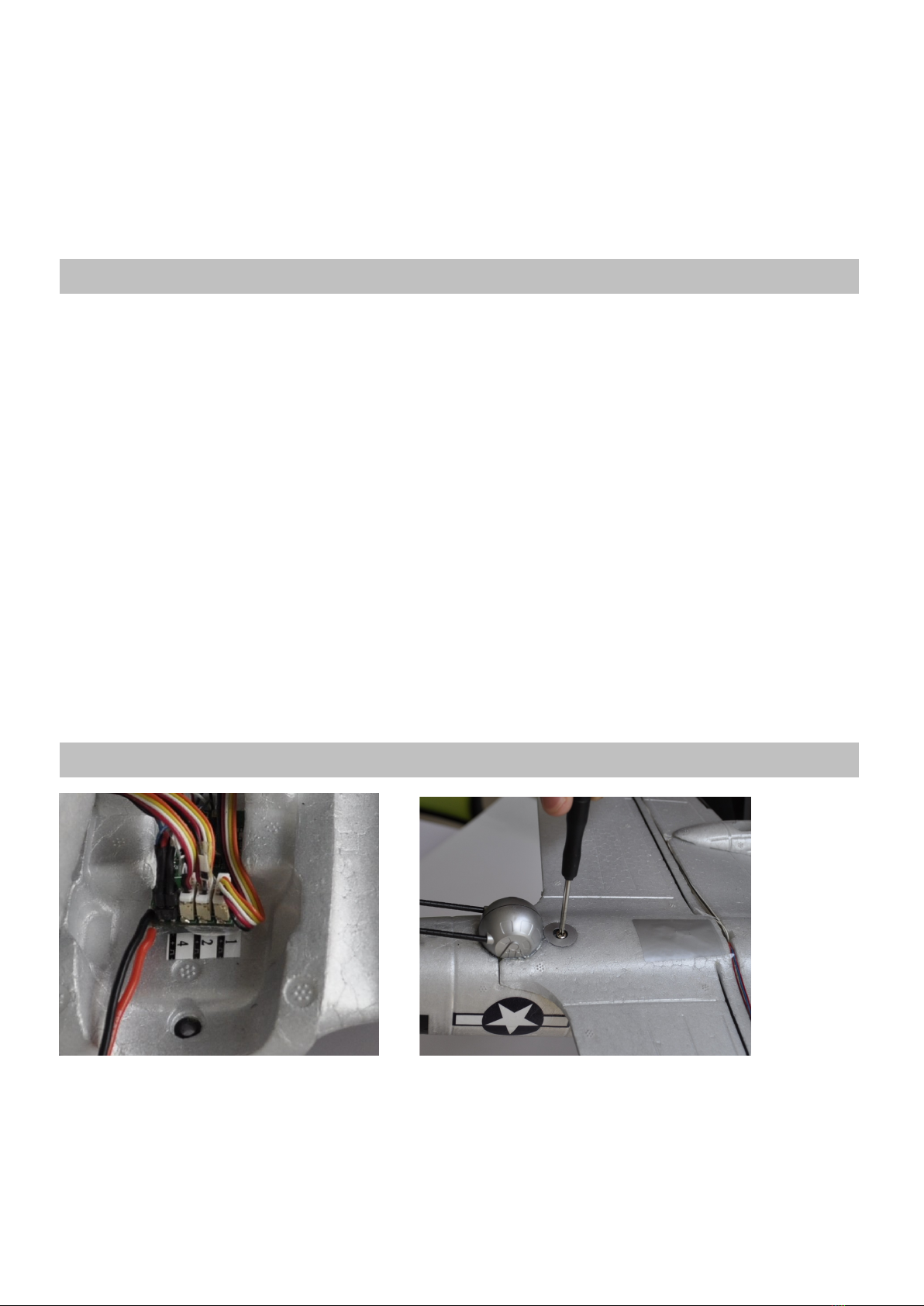
ITEMS TO BE COMPLETED

3
to surroundings.
LITHIUM POLYMER BATTERY RECYCLING
ATTENTION: The product you have purchased is powered by a rechargeable battery. At the end of the battery’s
useful life, under various state and local laws, it may be illegal to dispose of this battery into the municipal waste
system. Check with your local solid waste officials for details in your area for recycling options or proper disposal.
● Ailerons: The flight control on the airplane that controls the ability of the airplane to bank left and right.
● Center of Gravity (C.G.): Point at which the aircraft must balance in order to fly properly.
● Elevator: The flight control that controls pitch attitude. By adding power and pitching up, you can make the
model climb or loop.
● Glide Slope: The proper path for an airplane approaching a landing strip.
● Lithium Polymer (LiPo) Battery: Rechargeable battery which is used to power the airplane. LiPo batteries are
lighter and smaller than most other types of rechargeable batteries.
● Receiver: The unit in the aircraft that receives the signal from the transmitter to provide the input to the servos.
● Servo: The device on the model that moves the flight controls.
● Transmitter (TX): The hand-held unit that sends the signals to the control unit, or receiver (RX), in the aircraft.
Connect the servo plugs with receiver Fix the wing with screws
GLOSSARY
ASSEMBLE THE WINGS AND LANDING GEARS

4
Use the charging box included in the package to charge the lipo battery. The power source can be a connected
mobile phone adapter, power bank or car charger.
Illuminated green light indicates charging. When the LED goes out, charging is complete.
CHARGE THE LIPO BATTERY
TRANSMITTER FUNCTIONS

5
1. Power switch 2. Elevator / Aileron (mode 2) Throttle / Aileron (mode 1) 3. Aileron Trim 4. Elevator
Trim 5. Gyro switch 6. Throttle and Rudder (mode 2) Elevator / Rudder (mode 1) 7. Rudder Trim
8.Throttle Trim 9. Gyro PID tuning button
LINKING TO MICRO AIRCRAFT
Gyro OFF
Gyro ON
Low High
1. Power on the receiver.
2. Press and hold the upper right trim button, and
power on the transmitter.
3. Then wait for 3 seconds. When the LED flashes
rapidly, release the pressing fingers.
4. Linking completes when LED turns solid.
TRANSMITTER SETUP

6
Enter Setup
Press and hold the upper left
button, and power on the
transmitter. Enter the transmitter
setup when “BEEP” is heard.
Control
Surface
Reverse
MODE 2 :
MODE 1:
1. Elevator setting: Press and hold
button 1 until “BEEP” is heard, then
the direction is reversed;
2. Aileron setting: Press and hold
button 2 until “BEEP” is heard, then
the direction is reversed;
3. Rudder setting: Press and hold
the button 3 until “BEEP” is heard,
then the direction is reversed.
Gyro Reverse
MODE 2:
1. Elevator gyro setting: Press and
hold on button 4 until “BEEP” is
heard, then the direction is
reversed;
2. Aileron gyro setting: Press and
hold on button 5 until “BEEP” is
heard, then the direction is

7
MODE 1:
reversed;
3. Rudder gyroscope: Press and
hold on button 6 until “BEEP” is
heard, then the direction is
reversed.
RESET
Power on the transmitter. Press
and hold the upper left button and
upper right button. All parameters
are reset when “BEEP” is heard
(Trims return to center; all control
surfaces and gyro directions are
not reversed).
INSTALLATION AND REMOVAL OF THE LIPO BATTERY

8
Keep hands clear of the propellers during battery installation and removal.
Remove nose cone or battery cover. Use two fingers to secure connector during battery installation and
removal.
Press battery into place to secure. Replace nose cone or battery cover.
Disconnect and remove the battery after each flight by holding the battery lead with two fingers and removing the
battery from the lead with the other hand. Do not yank or jerk the battery from the aircraft. This could dislodge the
RX board from the Micro B-17 Flying Fortress.
CHECK THE CG

9
CHECK THE CONTROL SURFACE DIRECTION

10
Wrong gyro directions will lead to crashes. Check all 3 gyro directions before each flight:
CHECK THE GYRO DIRECTION
Head
Down
Head
Up
Roll
Right
Roll
Left

11
To alter the center position, or increase/decrease the control throw, follow these steps. Be sure to unplug the
battery from the model before attempting to mechanically adjust the linkage.
ADJUSTMENT OF LINKAGE
Turn
Right
Turn
Left

12
With the transmitter powered and the battery plugged into the Micro B-17 Flying Fortress, walk 50' [15m] from
the aircraft and check the control functions for proper and smooth operation.
If at anytime during operation, the controls or propellers become jammed or unresponsive, reduce the power to
the propellers and land. Fix the problem before attempting to fly.
Take off (or hand launch) heading directly into the wind.
NOTE: If you hand launch, you can remove the landing gear by gently pulling the landing gear wires straight out
of the mounts. It is highly recommended to cut power to the motors completely just before the propellers touch
the ground to prevent any damage.
Hand launch with throttle set at ¾ to full power, wings level and with a slight toss (it is not necessary to
aggressively throw this model to hand launch it).
Once in the air, gain altitude to allow yourself sufficient reaction time to make a correction during flight. Once
you’re comfortable, adjust the aileron and elevator trims one click at a time so that the Micro B-17 Flying Fortress
flies straight and level with the control sticks centered.
Concentrate on using small aileron control inputs so the model turns without banking the wings excessively. A
slight amount of up elevator may be necessary to maintain altitude going into a turn and the elevator will need to
be returned to neutral when coming out of a turn to avoid gaining altitude.
It’s recommended that you attempt to land before the motors lose power and don’t have enough voltage to
maintain altitude. Always land directly into the wind if possible. Gradually reduce power when you are close to
the landing spot and when close to the ground and about to touch down, pull the elevator stick back slightly to
raise the nose of the model and slow the landing speed to “flair” for landing. Unplug the battery from the model
and switch off the transmitter. Allow the motors to cool between flights.
To replace the propellers, firstly make sure the battery is unplugged. Remove the spinner by gently wiggling it
and breaking the glue joint that holds the spinner in place on the propeller. Gently and carefully hold the motor
shaft with needle nose pliers or a hemostat to keep it from rotating and gently unscrew the propellers from the
shafts. As shown in the picture, the left propeller unscrews clockwise and the right propeller unscrews
counterclockwise. BE SURE you replace the propeller with the same rotating direction propeller! The spinner
can be glued back on the propeller with a small amount of glue. Allow the glue to dry sufficiently before flying the
model. Gently pull on the spinner to make sure it is really glued to the propeller.
RANGE CHECK
FLYING THE MICRO
PROPELLER REPLACEMENT

13
Wingspan: 745mm/29.33in
Length: 540mm/21.26in
Wing Area: 7.8d ㎡
Wing Loading: 19.87g/d ㎡
Flying weight: 155g/5.47oz
Motor: Brushed φ8.5*20mm *4, 50000rmp
Battery: 3.7v(1s) 500mah 25C
Servos: 2.0g*3
Radio: 2.4ghz 5ch
Unscrew to remove propellers
SPECIFICATIONS
Table of contents
Popular Toy manuals by other brands

REVELL
REVELL GMC PICKUP WITH SNOW PLOW Assembly instructions

Fisher-Price
Fisher-Price Rain Forest Dancin’ Tunes owner's manual

Heli-scale
Heli-scale SUPER PUMA instruction manual

Fisher-Price
Fisher-Price Miracles & Milestones K5518 instruction sheet

Jamara
Jamara Ferrari LaFerrari instructions

Fisher-Price
Fisher-Price GeoTrax Oceanside Flier H8101 quick start guide

GREAT PLANES
GREAT PLANES Reactor instruction manual

Klein
Klein Bosch Service Station Assembly instructions

LEGO
LEGO 71234 instruction manual

Eduard
Eduard P-40N landing flaps Assembly instructions

Lionel
Lionel Train Master H-24-66 owner's manual

Carrera
Carrera Speedray PROFI RC Assembly and operating instructions