Easystreet Air Commander User manual

1
Technical Support
1-800-248-0892
Ext. 2
Air Commander
Part No. 27325, with air
Part No. 27332, without air
www.airliftcompany.com
Please read these instructions completely before proceeding with installation.
The oil level in the compressor must be checked BEFORE running the engine or
compressor. Failure to do so will result in a faulty compressor and a void warranty.
MN-494
(02204)
ECN 3827
Item Description Part Number Qty.
Compressor 24325 1
Serpentine Belt (with air) 10652 1
Serpentine Belt (without air) 10655 1
Alternator Pulley 10230 1
Clutch/Pulley Assembly 26615 1
Idler/Pulley Assembly 26630 1
Overflow Reservoir 21135 1
Coelescing Filter 21107 1
Inlet Filter 10670 1
Leader Hose 22024 1
Computer Bracket 10730 1
Compressor Plate 10755 1
Coolant Reservoir Bracket 10179 1
Upper Bracket 10761 1
Lower Left Bracket 10762 1
Lower Right Bracket 10763 1
Air Filter Bracket 10479 1
Brass Cross Bracket 26237 1
Compressor Fitting 21130 2
Compressor Sleeve Insert 21125 2
O-ring 21578 2
1/2" NPT Check Valve 21285 1
1/4" NPT Relief Valve 24290 1
110-145 p.s.i. Pressure Switch 24551 1
1/2" NPTM x 1/2" Tube Straight 21369 5
1/2" NPTM x 1/4" NPTF Bushing 21247 1
1/2" Brass Cross 21221 1
Plug 21190 1
1/2" NPTM x 1/8" NPTF Bushing 21251 1
1/2" NPTF Coupling 21220 3
Important Warranty Information
1. Ifthecompressoror engineis runwithout having
oil in the compressor, then the warranty is void.
2. If the belt is misinstalled or the belt does not
have the proper tension, then the warranty is
void.
3. Failure to use included installation components
properly voids the warranty.
4. Failure to check proper oil level and conditions
will void the warranty.
5. This compressor must only be used in an air
compressor application only, not an air
conditioning application. No freon is required.
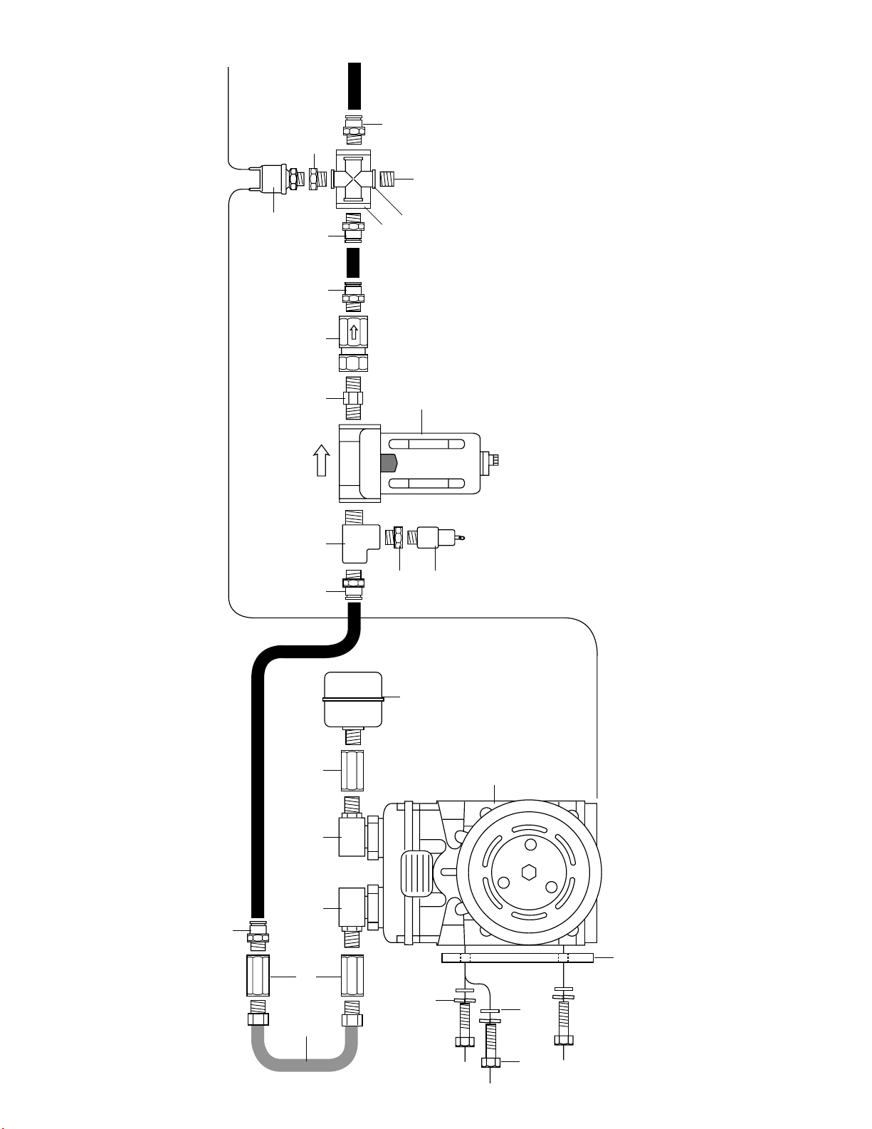
Front View Side View
InstallationComponents
EASYSTREET
A
B
C
D
E
F
G
H
I
J
K
L
M
N
O
P
Q
R
S
T
U
V
W
X
Y
Z
AA
BB
CC
DD
Item Description Part Number Qty.
1/2" Street Tee 21391 1
3/8"-16 x 3/4" Bolt 17101 2
3/8" Flat Washer 18444 9
3/8"-16 x 1 Carriage Bolt 17134 4
3/8"-16 x 7/8" Bolt 17187 3
3/8" Lock Washer 18427 7
3/8"-16 Hex Nut 18430 4
8mm-1.25 x 25mm Bolt 17177 1
8mm Flat Washer 18501 1
8mm Lock Washer 18503 1
Frame Clamp 10181 1
1/4"-20 x .75" Bolt 17175 8
Self Tapper 17102 2
5/16" Flat Washer 18405 6
10-32 x 3/8" Machine Screw 18496 2
1/4"-20 Kep Nut 18452 8
1/4" Hose Clamp Worm 10550 1
20 amp AGC Fuse 24739 1
Red 16 Gauge Wire 24643 8'
ATC/ATO Fuse Tap In 24542 1
Mini Fuse Adapter 24561 1
Butt Connector 24645 2
1/4" Female Terminal 24594 3
AGC Fuse Tap In 24543 1
3/16" Female Terminal 24524 1
Thread Sealant 23586 2
1/2" Nylon Hose 20966 15'
Hose Cutter 10530 1
Oil Dipstick 10159 1
Pipe Nipple 21729 1
EE
FF
GG
HH
II
JJ
KK
LL
MM
NN
OO
PP
QQ
RR
SS
TT
UU
VV
WW
XX
YY
ZZ
AB
AC
AD
AE
AF
AG
AH
AI

2
Technical Support
1-800-248-0892
Ext. 2
Figure 1
To Air Tank
To Keyed
Power Source
A
GG
L
II
JJ
DD DD
I
SS
J
Y
Y EE AI V Y Y
Y
BB
WH
CC
Z
X
R
AA

3
Technical Support
1-800-248-0892
Ext. 2
NOTE: This compressor will mount on the right
(passenger) side of the engine. It may be necessary to
relocate or remove the air conditioning lines. If the oil is
low in the compressor, use Polyol Ester (P.O.E.) P.A.G. oil
and fill to specified amount.
I. AssemblingtheCompressor
1. Attach the clutch to the compressor using the four bolts that
come in the box with the clutch (Figure 2). Tighten the bolts
securely. NOTE: Make sure that the wire is at the bottom right
hand side of the compressor.
2. Placethe pulley(E) overthe clutch and align thekeyway. Attach
the pulley (E) using the provided hardware. Tighten securely to
the shaft (Figure 4).
3. Attach the small clamp that came with the clutch using bolt (FF)
andflat washer (GG). Route the wirethroughtheclamp (Figure
3).
4. Attach the plate (L) to the left side of the compressor (engine
side) using bolts (II), lock washers (JJ), and flat washers (GG).
Be sure to insert the carriage bolt (HH) before bolting the plate
down (Figure 5). NOTE: The long tab at the bottom of the
bracket faces the rear of the compressor (Figure 5).
5. Removethesmallboltontheopensideofthecompressorabove
the line clamp previously installed and check the oil level in the
compressorwith the supplied dipstick(AH). The oil levelshould
be from 1”to 11/4" on the dipstick. The compressor should have
a total of 8 fl. oz. (237 ml). Use Polyol Ester (P.O.E.) P.A.G. oil
only. Attach the plug and tighten.
Figure 2
Figure 3
Figure 4
Figure 5

4
Technical Support
1-800-248-0892
Ext. 2
II. PreparingtheVehicle
1. Remove the belt, belt tensioner, positive battery cable, back
and side alternator bolts, computer and bracket, and radiator
overflow.
2. It will be necessary to slightly bend the inner fender to obtain
adequate clearance for the compressor. Use a pry bar or a 2 x
4 and pry using the frame (Figure 6).
3. Unbolt and move the evacuation line from the front of the
manifold to the rear of the manifold (Figure 7).
4. Removeandreplace the idler pulley with thepulley (F)supplied.
5. Attach bracket (P) and idler pulley back onto the vehicle using
the existing bolts removed (Figure 8). Tighten securely.
6. Install the upper bracket (N) using the existing bolt previously
removed (Figure 9). Leave loose at this time.
7. Installthebackbracket(O) using the 8mm bolt (LL), lockwasher
(NN), and flat washer (MM) provided. NOTE: The flange faces
to the rear of the vehicle. Leave loose at this time.
Figure 6
Figure 7
Figure 8
Figure 9

5
Technical Support
1-800-248-0892
Ext. 2
III. InstallingtheCompressor
1. Remove and replace the alternator pulley with the new pulley
(D) supplied.
2. Set the assembly unit in place. If the compressor still hits,
remove the assembly and adjust the fender.
3. Insertthe carriage bolt protruding from the compressor mounting
platethroughthetopbracket. Attachusing the flat washer(GG),
lock washer (JJ), and nut (KK). Leave loose at this time.
4. Insert three carriage bolts (HH) through the bottom mounting
holesand attach withflatwashers (GG), lockwashers (JJ), and
nut (KK). Leave loose at this time (Figure 10).
5. Tighten all the support bracket mounting bolts at this time (i.e.,
alternator, idler pulley, etc.).
6. Installthenewserpentinebelt(withair(B), NAPApart#25060945
or without air (C), NAPA part #25060849). Route the belt per
Figure 11. NOTE: Figure 11 is without air conditioning.
7. Be sure that the compressor and belt is fully aligned before
securing the mounting hardware. If not aligned, unattach the
beltandadjust the compressor as needed. Tighten all mounting
and bracket hardware only when all is fully aligned.
8. Attachthenegative cable, alternator wire,and clutch wire tothe
compressor using clamp (OO), bolt (FF), and flat washer (GG)
supplied (Figure 12).
IV.Reinstalling the Computer
1. Attach the computer bracket (K) to the fender using existing
nuts previously removed (Figure 13).
2. Attach the computer to the bracket using bolt (PP), flat washer
(RR), and nut (TT) supplied. Attach the wiring harness to the
computer, if disconnected.
Figure 10
Figure 11
Figure 12
Figure 13

6
Technical Support
1-800-248-0892
Ext. 2
V. Installing theRadiatorOverflow
Reservoir
1. Remove the two bolts on the ABS/brake bracket on the driver
side fender (Figure 14) and attach the bracket (M) to the ABS
brake bracket using existing bolts removed.
2. Loosely attach the reservoir (G) to the bracket using bolts (PP),
flat washer (RR), and nuts (TT).
3. Mark the fender at the bottom using the bottom hole on the
reservoir, center punch and drill a 1/4" hole, being careful no to
drill the tire. Reattach the reservoir in all three mounting
locations.
4. Pull the overflow hose out of the clamps under the radiator.
Reroute to the bottom of the reservoir. Cut and attach the hose
usingclamp (UU) provided. Filltheradiatorhalf way with radiator
fluid (Figure 14).
VI. Checking the Belt
1. Attach the positive battery cable.
2. Check all hardware to be sure that it is secure.
3. Start the engine and observe the belt and pulley for alignment.
NOTE: DO NOT ENGAGE CLUTCHYET. Adjust if necessary.
VII. Installing the Filter
1. Using the provided thread sealant, assemble the bushing (Z)
and relief valve (W) to the brass street tee (EE). Install a 1/2"
NPTM x 1/2" tube straight fitting (Y) to the tee (Figure 1).
2. With the arrow pointing in the direction of the flow, assemble
the coelescing filter (H) to the brass tee assembly using the
supplied sealant (Figure 1). Tighten securely.
3. Securelyattach a 1/2" NPTM x 1/2" tube straightnipple (AI) to the
port on the coelescing filter (Figure 1).
4. Looselyattach the filter bracket (Q)tothefilterusing the provided
screws (SS).
5. Find a remote location on the frame or in the rear with enough
clearance to install the filter assembly and use filter bracket as
atemplate to mark mounting locations. Removefilterassembly
and drill the mounting hole locations with a 1/4" bit.
6. Remove the filter from the bracket and install the bracket using
the self tapping bolts (QQ). Tighten securely (Figure 15).
7. Reattach the filter to the bracket and tighten screws securely
(Figure 15).
Previously
attached
to vehicle
Figure 14
Figure 15

7
Technical Support
1-800-248-0892
Ext. 2
VIII. InstallingtheHoseAssembly
1. Install the brass cross bracket (AA). Using the bracket (R) as a
template, mark and drill the two 1/4" mounting holes and attach
using two bolts (PP) and two nuts (TT).
2. Attach the bushing (CC) and pressure switch (X) to one leg of
the brass cross (AA) and plug (BB) to the other leg directly
across from the pressure switch (Figures 1 and 16).
3. Attach the brass cross to the bracket using a 1/2" NPTM x 1/2"
tube straight fitting (Y) on each side (Figures 1 and 16).
4. Install a 1/2" NPTM x 1/2"tube straight fitting(Y) to oneendof the
check valve (V) (Figure 1). Tighten securely. The check valve
will be installed to the filter assembly. NOTE: The arrow points
inthedirectionofthe flow and the fitting goes onto thedischarge
end of the check valve.
5. Use the provided hose cutter (AG) to cut a length of ½" hose
long enough to run from the cross assembly to the air fitting on
the filter assembly. Do not attach at this time.
6. Being sure that the arrow on the check valve points in the
direction of the flow, attach one end of the hose into the push-
to-connect fitting on the check valve. Route the other end to
the fitting on the cross assembly (Figure 1).
7. The open leg on the cross routes into a 1/2" hose going to the
existing air tank (Figure 1).
Bushing Compressor
Fitting
Compressor
L
eader Hose
To Air TankTo Check Valve
Figure 16
Figure 17
8. Using the thread sealant provided, assemble two of the brass couplings (DD) to both ends of the steel leader hose
(J). Tighten securely (Figures 1 and 17).
9. Remove the caps to the discharge and supply ports on the top of the compressor.
10. Slide the O-rings (U) around the two sleeve inserts (T). Set the inserts into the port holes on top of the compressor.
11. Set the compressor fittings (S) over the inserts and loosely attach using the existing bolts removed.
12. Attach a coupling (DD) and filter (I) to the supply side (the side closest to the engine) using the provided sealant.
Position the filter and tighten the compressor fitting bolt securely.
13. Firmly attach the steel leader hose to the remaining compressor fitting using the provided sealant (Figures 1 and
11).
14. Attach a 1/2" NPTM x 1/2" tube (Y) fitting to the opposite end of the leader hose.
15. Tighten the bolts on both compressor fittings securely.
16. Attach a length of hose (AF) from one end of the leader hose to the fitting on the relief valve assembly on the filter
(Figure 1).
IX. Checking the Oil
Use a dipstick (AH) to check the oil depth. The depth must be between 1" and 11/4" (Figure 13). If this is not done, the
warrantywill be void.

8
Technical Support
1-800-248-0892
Ext. 2
Figure 18
ImportantWarranty Information
1. If the compressor or engine is run without having oil in the compressor, then the warranty
is void.
2. If the belt is misinstalled or the belt does not have the proper tension, then the warranty is
void.
3. Failure to use included installation components properly voids the warranty.
4. Failure to check proper oil level and conditions will void the warranty.
5. This compressor must only be used in an air compressor application only, not an air
conditioning application. No freon is required.
6. It is necessary to periodically check the filter for trapped oil. This needs to be performed
three or four times a year. Failure to do so will result in reduced component life.
X. Wiring the Electrical System
1. The hot lead to the compressor is the black wire on the clutch. Cut off the fitting on the end of the black wire and
using butt connector (ZZ), splice a length of the red wire (WW) to the black wire. Run red wire to spade terminal on
the pressure switch. Attach a blue spade connector (AB) to the red wire and attach to one of the terminals on the
pressure switch.
2. Splice the 20 amp fuse in the fuse box using the adapters provided into a hot keyed power source and run it to the
other terminal on the pressure switch.
3. After all hardware has been secured and oil level is within range, the system is now ready to operate. See Figure
18 for a finished installation.
4. We recommend purchasing a spare belt to carry in the vehicle in case of a belt failure.
5. Check all fittings and air line connections for leaks with a solution of 1/5dish soap to 4/5water in a spray bottle.

9
Technical Support
1-800-248-0892
Ext. 2

10
Technical Support
1-800-248-0892
Ext. 2
“The Choice of the Professional Installer”
For Technical Assistance call 1-800-248-0892
Thank you for purchasing Air Lift Products
Mailing Address: Street Address:
AIR LIFT COMPANY AIR LIFT COMPANY
P.O.Box 80167 2727 Snow Rd.
Lansing, MI 48908-0167 Lansing, MI 48917
Local Phone: (517) 322-2144
Fax: (517) 322-0240
www.airliftcompany.com
Printed in the USA
EASYSTREET
This manual suits for next models
2
Table of contents
Popular Air Compressor manuals by other brands

Gardner Denver
Gardner Denver AirSmart VS20A Operating and service manual

ULTIMATE SPEED
ULTIMATE SPEED UMK 10 C2 Operation and safety notes translation of the original instructions

Power first
Power first 2 Gallon Air Compressor user manual

Scheppach
Scheppach 5906118901 Translation of original instruction manual

ULTIMATE SPEED
ULTIMATE SPEED UMK 10 B2 Operation and safety notes translation of the original instructions

Clarke
Clarke AIR PIONEER 100 Operating and maintenance instructions