Sealey Power PRODUCTS SA1565 User manual

Familiarise yourself with the application and limitations of the
compressor.
Ensure that the compressor is in good order and condition before
use. If in any doubt do not use the compressor and contact a
service agent.
WARNING! Compressor must only be serviced by an
authorised agent. DO NOT tamper with, or attempt to adjust
the pressure switch or the safety valve.
Before moving or maintaining the compressorensure that the air
tank pressure has been vented.
Only use recommended attachments and parts. Unapproved
items may be dangerous and will invalidate the warranty.
Read the instructions for any accessory used with the
compressor. Ensure that the safe working pressure of any air
appliance used, exceeds the output pressure of the compressor.
If using a spray gun, check that the area selected for spraying is
provided with an air change system or adequate ventilation.
Ensure that the air supply valve is turned off before disconnecting
the air supply hose.
Use the compressor in a well ventilated area and ensure it is
placed on a firm surface. Remember that the compressor
engine produces harmful exhaust fumes.
Keep tools and other items away from the compressor when it is
in use, and keep work area clean.
Ensure that air hoses are not tangled, twisted or pinched.
Keep children and unauthorised persons away from the work area.
DO NOT dis-assemble the compressor for any reason if you are not
qualified to do so. The unit must be checked by qualified personnel
only.
DO NOT operate the compressor within the vicinity of flammable
liquids, gases or solids.
DO NOT touch compressor cylinder, cylinder head or pipe from
head to tank as these may be hot and will remain so for some
time after shutdown.
DO NOT operate the compressor without all safety guards in
place.
DO NOT attempt to move the compressor by pulling the air tool
hose.
DO NOT use the compressor for a task for which it is not
designed.
DO NOT deface the certification plate attached to the compressor
tank.
DANGER! DO NOT direct the output jet of air towards people
or animals.
DO NOT operate the compressor without an air filter.
DO NOT allow anyone to operate the compressor unless they
have received full instructions.
For safety instructions relative to the maintenance and use of the
petrol engine - refer to the engine manufacturer’s handbook
supplied.
DO NOT check the ignition system by removing the spark plug or
spark plug lead. Use specific tester or contact service agent.
WARNING! DO NOT touch the spark plug or plug lead whilst
the engine is running - severe, potentially fatal, electric
shock may result.
Ensure that engine fuel is stored in an approved container. For
long term storage ensure that the fuel tank is drained and that
the compressor is adequately protected.
DO NOT smoke or have any naked flames nearby whilst
re-fuelling.
DO NOT leave the compressor operating unattended.
DO NOT remove the fuel cap, or try to refuel whilst the engine is
running. Stop the engine and allow it to cool for two minutes
before attempting to refuel.
DO NOT refuel in a closed or poorly ventilated environment as
there is a danger of explosion or fire. Refuel outdoors.
DO NOT operate the compressor if there is a fuel leak. Move the
unit to a safe area, where there is no risk of ignition, until the leak
has been rectified and the machine is dry.
DO NOT start the engine if there are any flammable materials
near the exhaust system or in the path of the exhaust gases.
DO NOT block the engine ventilation grilles.
DO NOT cover the compressor or restrict air flow around the
machine whilst it is operating.
WARNING! The air tank is a pressure vessel and the
following safety measures apply:
DO NOT tamper with the safety valve and DO NOT modify or
alter the tank in any way and DO NOT strap anything to the tank.
DO NOT subject the tank to impacts, vibration or to heat and
DO NOT allow contact with abrasive or corrosive materials.
DO drain condensation from tank daily and inspect inside
walls for corrosion every 12 months.
The tank shell must not fall below the certified thickness at
any point.
When not in use, store the compressor carefully in a safe, dry,
childproof location.
When the compressor is not in use, it should be switched
off and the air drained from the tank.
INSTRUCTIONS FOR:
COMPRESSOR 150LTR BELT
DRIVE PETROL ENGINE 6.5HP
MODEL No: SA1565
Thank you for purchasing a Sealey product. Manufactured to a high standard, this product will, if used according to these instructions and
properly maintained, give you years of trouble free performance.
1. SAFETY INSTRUCTIONS
IMPORTANT: PLEASE READ THESE INSTRUCTIONS CAREFULLY. NOTE THE SAFE OPERATIONAL REQUIREMENTS, WARNINGS AND
CAUTIONS. USE THE PRODUCT CORRECTLY AND WITH CARE FOR THE PURPOSE FOR WHICH IT IS INTENDED. FAILURE TO DO SO MAY
CAUSE DAMAGE AND/OR PERSONAL INJURY AND WILL INVALIDATE THE WARRANTY. PLEASE KEEP INSTRUCTIONS SAFE FOR FUTURE USE.
Original Language Version SA1565 Issue: 2 - 20/02/12

2. INTRODUCTION & SPECIFICATION
Static compressor with Honda GX200 6.5hp power unit coupled to
heavy-duty, two stage twin piston, cast iron pump. Pump has heavy-
duty full cast cylinders capped by alloy heads for improved heat
dissipation and long life. Heavy-duty drive guard protects belt and
flywheel that is designed to force air over the pump to aid cooling.
Features single gauge and air outlet. Runs on unleaded fuel.
3. PREPARATION
3.1. Remove compressor from packaging and inspect for any
missing or damaged parts. If anything is found to be missing
or damaged contact your supplier.
3.2. Save the packing material for future transportation of the
compressor. It is recommended to store the packing in a safe
location, at least for the period of the guarantee. Then, if
necessary, it will be easier to send the compressor to the
service centre.
3.3. Take care to transport the compressor correctly, do not
overturn it or lift it with hooks or ropes.
3.4. Positionthecompressoronaatsurfaceorwithamaximum
permissible inclination of 10°. Site in a well ventilated area.
If the surface is inclined and smooth, check if the compressor
moves whilst in operation.
If the surface is in a raised position, make sure the
compressor cannot fall, securing it in a suitable way.
3.5. Toensuregoodventilationandefcientcooling,the
compressor’s belt guard must be at least 100cm from any
wall.
3.6. Before using the compressor, check the oil level by looking
at the dipstick as shown in fig.5C. If the oil is not between the
min and max. mark, it should be topped up with synthetic oil
(see section 5.4. for recommended oils). We do not
recommend using mineral oil in these compressors. Do not
overfill.
3.7. The compressor should be located in a position that allows
good air circulation around the unit and where there is good
ventilation. Remember that the compressor's engine
produces harmful exhaust fumes.
2.1. SPECIFICATION
4. OPERATION
WARNING! Ensure that you read, understand and apply
Section 1 Safety Instructions.
4.1. STARTING
IMPORTANT! Always check and, if necessary, top-up the
engine oil and the pump oil before starting. Severe engine
and/or pump damage may otherwise result.
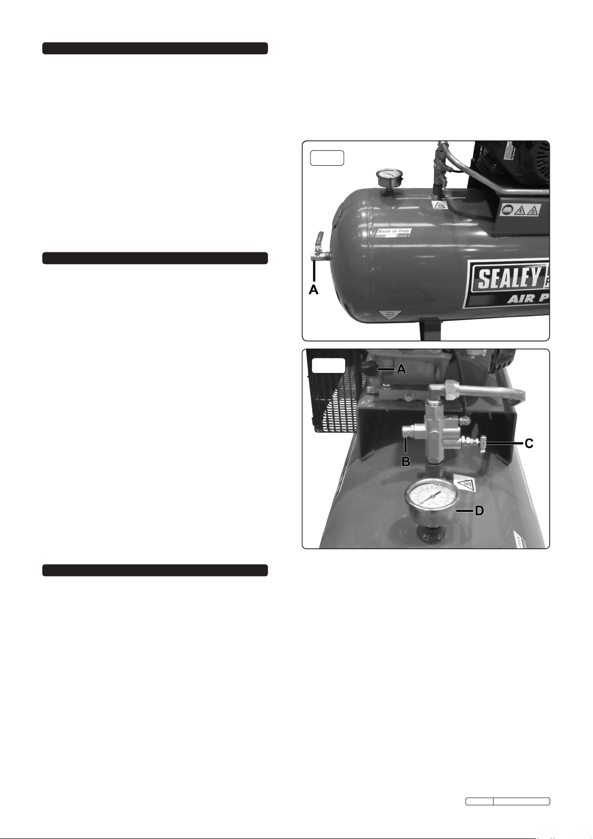
4.1.1. Check that the air outlet valve on the tank end-plate (fig.1.A)
is closed.
4.1.2. Start the compressor engine, following the procedure
detailed in the manufacturer’s handbook supplied.
Ensure the oil is topped up. Oil filler/dipstick - fig.2A.
4.1.3. When the engine is running smoothly, the compressor will
operate automatically, building up the pressure in the tank,
which is shown on the pressure gauge (fig.2D), to the
maximum setting (factory set). When the maximum tank
pressure is reached, the relief valve (fig.2B) will
automatically vent the pump output. When the tank
pressure falls below the minimum threshold
(approx.2bar/29psi less than the maximum pressure), the
relief valve will automatically close, and the tank pressure will
increase back to it's maximum.
fig.1
Model No: ..........................SA1565
Engine Output: ........................6.5hp
Speed............................1500RPM
Noise Level: ........................ 97dB.A
Noise LwA Level: .....................99LwA
Air Displacement:....................20.9cfm
Maximum Free Air Delivery: ...........15.2cfm
Width x Depth x Height:... 1360 x 540 x 1110mm
Tank Capacity: ........................150ltr
Maximum Pressure: ..............145psi/10bar
Weight: .............................103kg
4.2. STOPPING.
4.2.1. To stop the compressor turn the engine ignition switch (fig.3)
to Off (O). See the engine manufacturer’s handbook for the
complete engine shutdown procedure.
4.3. CONNECTING AIR POWERED EQUIPMENT.
4.3.1. After fitting the desired coupling to the outlet valve (fig.1)
connect an air hose and hook up to air system. An outlet
regulator is necessary to use air equipment direct from the
compressor.
Note: To determine the correct working pressure and air flow
requirements for any piece of equipment check the
corresponding manual. Be aware that the air flow figure
stated on tools and accessories refers to ‘Free Air Delivery’
and not the piston displacement of the compressor. When
adjusting the regulator, always adjust up to the required
pressure.
4.4. WHEN WORK IS COMPLETE.
At the end of each working day, drain any moisture from the
main tank. Place a container under the drain plug and then
carefully unscrew it (fig.4). DO NOT allow moisture to
accumulate in the tank as this will corrode the inside of the
tank and affect the pressure rating of the tank.
WARNING! Wear safety goggles and gloves when performing
this task.
fig.2
Note: a) If the relief valve does not cut in and out, but is
continuously closed whilst using an air appliance, the
capacity of the compressor may be too small for the
equipment or tool.
b) The gauge (fig.2D) indicates the pressure inside the tank,
NOT the pressure supplied to the air equipment. If the
pressure in the tank exceeds the relief valve maximum, a
safety valve (fig.5E) will open. WARNING! For this reason
DO NOT tamper with, or adjust, the relief valve or the
safety valve.
Original Language Version SA1565 Issue: 2 - 20/02/12

5. MAINTENANCE
fig.3
In order to keep the compressor in good working condition, periodic
maintenance is essential.
IMPORTANT! Failure to carry out maintenance tasks may
invalidate the warranty on your compressor.
WARNING! Service and maintenance must be performed by an
authorised agent. DO NOT tamper with, or attempt to adjust, the
pressure switch or safety valve. Before moving, or carrying out
any maintenance on the compressor, ensure that the ignition
switch is ‘off’, that the air tank pressure has been vented and
the compressor has been allowed to cool down for a period of
time.
5.1. ENGINE.
For all engine maintenance, please refer to the engine
manufacturer’s handbook (supplied) for the full schedule.
5.2. COMPRESSOR.
5.2.1. Operations to be carried out after the first 50 working
hours:
a) Check that all bolts/nuts are tight, particularly those
retaining the crank case and cylinder head.
b) Replace the lubricating oil - see para 5.2.5.
5.2.2. Operations to be carried out daily:
a) Drain condensation by opening the valve (fig.4) located
under the tank.
b) Check oil level (fig.5C) and, if necessary, top-up.
c) Check guards/covers are secure.
d) Check for oil leaks.
e) Check for unusual noises or vibrations.
f) Check for air leaks.
5.2.3. Operations to be carried out weekly:
(or more frequently, if the compressor operates in a
very dusty atmosphere):
a) Remove the air filter element by undoing the screw
(fig.5B) and removing the filter cover. Clean the filter by
blowing through from the clean side, with an air line at
low pressure. Replace filter, cover and screw. DO NOT
operate compressor without filter as foreign bodies or
dust could damage the pump and will invalidate
warranty.
WARNING! Wear safety goggles when performing this
task.
b) Clean compressor.
c) Check that the relief valve, vents pump output and
reduces engine speed when maximum pressure is
reached.
Also that the compressor restarts pressure build up
automatically at 2bar below max pressure.
5.2.4. Operations to be carried out monthly:
a) Check belt tension. A weight of 3kg applied at the belt
mid-point should give a deflection of approximately
10mm (fig.6). If adjustment is required, maintain the
alignment of the two pulleys (fig.6). Adjust by
repositioning the engine, using the screw adjuster
provided in the base plate.
5.2.5. Operations to be carried out every 200 working hours:
a) Change air filter element. (See 5.2.3).
b) Replace the lubricating oil. For oil specifications see 5.4.
Remove the dipstick (fig.5C) and (after placing a
suitable container under it) undo the oil drainer (fig.5D).
Drain when the compressor has recently run, so the oil
is hot, the oil will drain rapidly and completely. Replace
the oil drainer and refill through the filler aperture.
Do not overfill. Replace the dipstick.
WARNING! Never mix different oils and do not use
non-detergent/low quality oils as the compressor
may be damaged and will invalidate the warranty.
WARNING! Dispose of waste oil only in accordance
with local authority requirements.
c) Check all tube fittings and electrical connections.
d) Inspect pressure tank inside and out for damage or
corrosion.
NOTE: It is recommended that every two years
(or approximately every 1600 working hours), the
compressor is returned to an authorised dealer for a
complete inspection.
ALIGNMENT
fig.4
fig.6
fig.5
Original Language Version SA1565 Issue: 2 - 20/02/12

Maintenance
Operations. Weekly.Daily. Monthly. 200 hrs.
Drain condensation. •
Check oil level. •
Check guards/covers. •
Check for oil leaks. •
Replace air filter.
Check fittings.
Inspect Pressure Tank.
Change pump oil.
Check belt tension.
Clean air filter.
Check safety relief valve.
Clean compressor.
Check for air leaks.
Check for noise or
vibration.
•
•
•
•
•
•
•
•
•
•
5.3. SCHEDULED MAINTENANCE TABLE (NOT ENGINE)
NOTE: It is our policy to continually improve products and as such we reserve the right to alter data, specifications and component parts without prior notice.
IMPORTANT: No liability is accepted for incorrect use of this product.
WARRANTY: Guarantee is 12 months from purchase date, proof of which will be required for any claim.
INFORMATION: For a copy of our latest catalogue and promotions call us on 01284 757525 and leave your full name and address, including postcode.
01284 757500
01284 703534
sales@sealey.co.uk
Sole UK Distributor, Sealey Group,
Kempson Way, Suffolk Business Park,
Bury St. Edmunds, Suffolk,
IP32 7AR
www.sealey.co.uk
Web
email
Original Language Version SA1565 Issue: 2 - 20/02/12
Environmental Protection.
Recycle unwanted materials instead of disposing of them as waste. All tools, accessories and packaging should be
sorted, taken to a recycle centre and disposed of in a manner which is compatible with the environment.
When the product is no longer required, it must be disposed of in an environmentally protective way.
Parts support is available for this product. To obtain a parts listing and/or diagram, please log on to www.sealey.co.uk,
email sales@sealey.co.uk or phone 01284 757500.
5.4. Recommended oils
Synthetic oil suitable for temperatures ranging from -5°C to
45°C: viscosity 5W50. We DO NOT recommend using mineral
oil in this compressor.
Part No. Qty. Description
FSO1 1ltr x 12 Compressor oil fully synthetic
FSO1S 1ltr x 1 Compressor oil fully synthetic
FSO5 5ltr x 1 Compressor oil fully synthetic
5.5. IMPORTANT WARNING - Air contaminants taken into the
compressor will affect optimum performance. Example: Body
llerdustorpaintoverspraywillclogthepumpintakelterand
may cause internal damage to pump/motor components.
Please note that any parts damaged by any type of
contamination will not be covered by warranty.
6. TROUBLE SHOOTING
Fault Cause Remedy
Pressure drop in the
tank.
Air leaks at
connections.
Run compressor to max.
pressure, switch off.
Brush soap solution over
connections and look for
bubbles. Tighten connections
showing leaks. If problem
persists contact Authorised
Service Agent.
Pressure switch
valve leaks when
compressor is idle.
Non-return valve seal
defective.
Discharge all tank pressure.
Contact Authorised Service
Agent.
Compressor stops
and does not restart.
Power failure.
Motor failure.
Check electricity supply and
fuse.
Contact Authorised Service
Agent.
Compressor does
not stop at max
pressure.
Pressure switch fault. Contact Authorised Service
Agent.
Compressor does
not reach max
pressure.
Filter clogged.
Head gasket or valve
fault.
Replace filter element.
Contact Authorised Service
Agent.
Compressor noisy
with metallic knock.
Low oil level.
Bearing or piston
damage.
Turn off and top up oil
immediately.
Contact Authorised Service
Agent.

Table of contents
Other Sealey Air Compressor manuals

Sealey
Sealey SAC2103B.V2 User manual

Sealey
Sealey SAC1903B User manual

Sealey
Sealey SAC3153B User manual

Sealey
Sealey SAc05030 User manual

Sealey
Sealey SAC42755B User manual

Sealey
Sealey Auto Service RE229 User manual

Sealey
Sealey MAC03 User manual

Sealey
Sealey MAC2300 User manual

Sealey
Sealey SAC1903B User manual

Sealey
Sealey SAC9030VE User manual

Sealey
Sealey SA22503 User manual

Sealey
Sealey SAC5020E.V2 User manual

Sealey
Sealey SACV52775B User manual

Sealey
Sealey SAC106B User manual

Sealey
Sealey MS163 User manual

Sealey
Sealey RE225.V3 User manual

Sealey
Sealey SAC0502B User manual

Sealey
Sealey SAC10030VE User manual

Sealey
Sealey SA5040 User manual

Sealey
Sealey SAC42055B User manual