Eaton Sefelec 64-SC User manual

.
USER MANUAL for:
SEFELEC 64-SC
PENT7761 reference
(ENGLISH)

SEFELEC 64-SC series user manual 1 V1.01
CONTENTS
Introduction...........................................................................................................................3
Guarantee ......................................................................................................................4
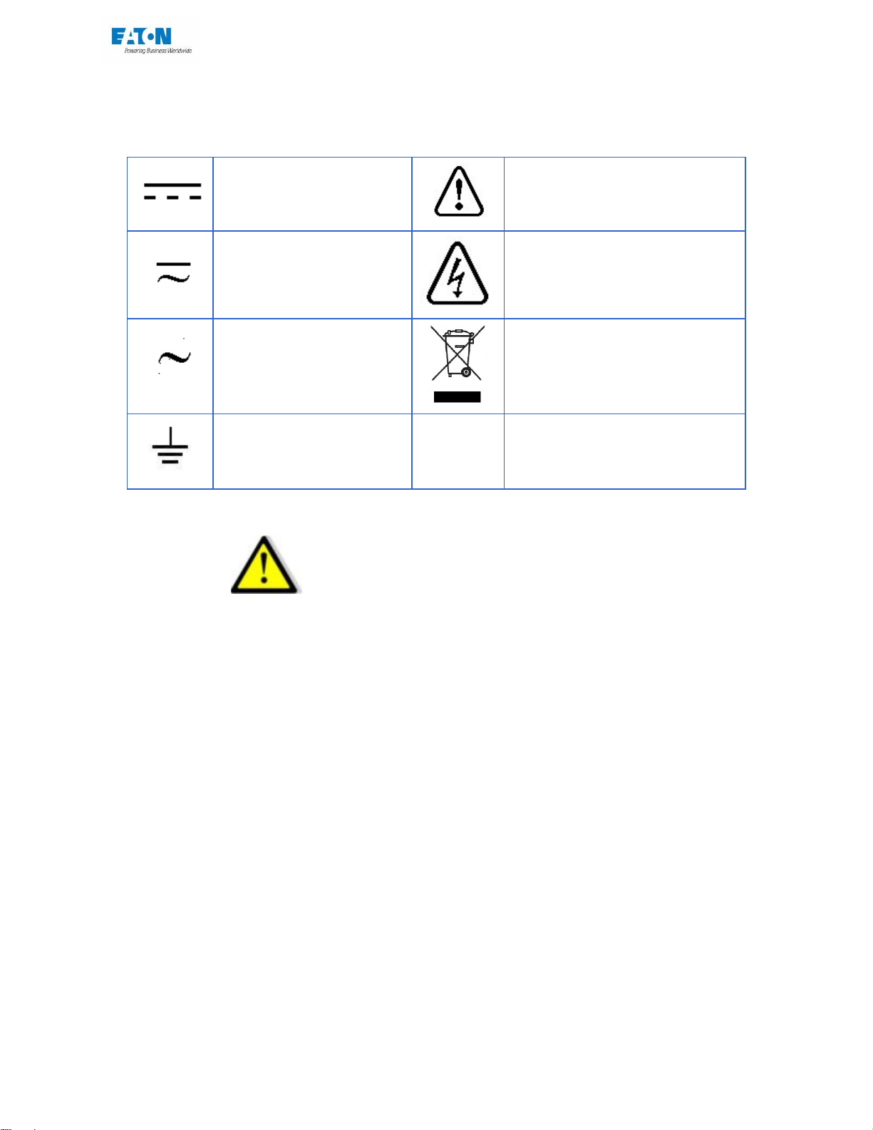
Pictograms used.............................................................................................................5
Warning and safety instructions......................................................................................7
Declaration of Conformity...............................................................................................8
Qualification of the personnel .........................................................................................8
Exclusion of liability ........................................................................................................8
Service Department........................................................................................................9
Presentation of the device...................................................................................................10
The various models in the Sefelec 64-SC range...........................................................10
References for the internal scanner..............................................................................11
References for the external scanner.............................................................................12
Specifications......................................................................................................................13
Over-voltage category..................................................................................................13
Pollution degree ...........................................................................................................13
Safety class..................................................................................................................13
Environment.................................................................................................................13
General characteristics.................................................................................................14
Specifications of the measurement channels................................................................15
Safety .................................................................................................................................29
Safety when working with electrical equipment.............................................................29
Safety devices..............................................................................................................29
4.2.1. Safety loops.........................................................................................................30
4.2.2. Optimising the safety............................................................................................31
Precautions for use.......................................................................................................32
Operating principle..............................................................................................................33
Channel module - Strength-Insulation...........................................................................33
Channel module - Earth continuity................................................................................34
5.2.1. Schematic diagram for the internal scanner (4-wire measurement with 2-wire
switching):...........................................................................................................................34
5.2.2. Schematic diagram for the external scanner (4-wire measurement with 2-wire or 4-
wire switching):...................................................................................................................35
5.2.3. External scanner: 4-wire measurement with 2-wire switching...............................36
5.2.4. External scanner: 4-wire measurement with 4-wire switching...............................37
Commissioning...................................................................................................................38
Content when delivered................................................................................................38
Instructions for rack mounting.......................................................................................40
Connecting an external scanner to a 5x device...................................................................42
General structure of the example..................................................................................42
Rack addressing...........................................................................................................43
Distribution of measurement channels, configuration example .....................................44
Rear panel Connections...............................................................................................45
Turning on the device .........................................................................................................46
Operating the external scanner...........................................................................................51
Sequential exploration mode for channels X to Y..........................................................51

SEFELEC 64-SC series user manual 2 V1.01
9.1.1. Programming a dielectric strength test .................................................................51
9.1.2. Programming an insulation measurement............................................................58
9.1.3. Programming an earth continuity measurement...................................................58
Non-sequential exploration mode:................................................................................65
9.2.1. Programming a dielectric strength test .................................................................65
9.2.2. Programming an insulation measurement............................................................70
9.2.3. Programming an earth continuity measurement...................................................70
The internal scanner...........................................................................................................71
Using the internal scanner:...........................................................................................74
Updating the Firmware of the relay control card of the external scanner:............................75
List of RS-232C, Ethernet, USB, IEEE488-2 commands.....................................................76
12.1.1. Standardised requests .........................................................................................77
12.1.2. Device-dependent controls...................................................................................78
12.1.3. Summary of the special commands for the scanner via the RS232, Ethernet, USB,
IEEE488-2 link....................................................................................................................84
12.1.4. Operating fault on the RS232C serial link.............................................................85
Direct control of the relays (Sefelec 64-SCPLC) .................................................................86
Control of the earth continuity modules.........................................................................87
Control of the Strength-Insulation modules...................................................................88
Control of the Strength-High Insulation modules...........................................................89
Pin arrangement of connectors C1 to C4......................................................................90
Layout of REAR panel sockets............................................................................................92
rear panel description...................................................................................................92
Maintenance and calibration...............................................................................................93
Preliminaries.................................................................................................................93
Return of Equipment.....................................................................................................93
Maintenance.................................................................................................................93
End-user license agreement...............................................................................................95
EU declaration of conformity.............................................................................................100

SEFELEC 64-SC series user manual 3 V1.01
INTRODUCTION
General points
These instructions present the SEFELEC 64-SC series, a channel scanner intended to be used
with a device in the 5x range.
According to the number of channels required, the scanner has the form of additional cards in-
stalled in a device in the 5x series (internal scanner - max. 8 channels) or in the form of a 19’’
rack 3U high in which 8-channel modules are integrated with a maximum of 8 modules per rack.
These modules are intended for several types of measurement:
- Strength/Insulation
- Ground continuity.
According to need, it is possible to equip a rack with 1 to a maximum of 8 modules of one type,
of the other or any combination of these modules.
In the event more than 64 channels are needed, it is possible to connect one or more extension
racks to the first rack with a max. of 64 channels each with a maximum of 8 racks (i.e. 512
channels).
The SEFELEC 64-SC scanner makes it possible to automatically conduct dielectric strength
tests, high-value insulation resistance measurements and earth continuity measurements on
several test points.
The information required for usage in accordance with the rules in effect for safe operation,
commissioning and maintenance of devices is provided in the instructions.
Since 1965, the mission of our teams has been the designing and manufacturing of electrical
resistance measuring devices, dielectric strength testers and cable testers.
Our experience in these fields has been recognised by most companies using leading-edge
technologies in military, aeronautic, railway-related and civilian fields.

SEFELEC 64-SC series user manual 4 V1.01
GUARANTEE
EATON guarantees that this appliance is free from any construction and packaging defect.
EATON also guarantees that the appliance will comply with the characteristics indicated in this
document when used correctly.
If the appliance does not comply with its specifications in the year following its initial delivery, it
will be repaired free of charge at our premises in Lognes.
Modifications to the appliance or one of its accessories carried out without the approval of
EATON shall cancel this guarantee.
EATON is not liable for any indirect damage resulting from use of the appliance.
ATTENTION: The characteristics indicated are valid for switching condi-
tions with a zero voltage and zero current (cold switching).

SEFELEC 64-SC series user manual 5 V1.01
PICTOGRAMS USED
Warnings are used in these instructions with symbols that must be complied with to guarantee
safe operation of the devices.
The warnings and symbols used in these instructions are:
ATTENTION
Indicates imminent danger.
Death or very serious injury may occur if suitable safety measures are not tak-
en.
CAUTION
Indicates a situation which may be dangerous.
Slight injury may occur if suitable precautionary measures are not taken.
IMPORTANT
Indicates a situation which may be dangerous.
Damage to equipment or to parts of the installation may occur, if suitable pre-
cautionary measures are not taken.
NOTE
Indicates important information on the device.

SEFELEC 64-SC series user manual 6 V1.01
The following symbols may appear on the devices:
Direct current
Attention (See accompanying
documents).
Direct current and alternat-
ing current.
Caution: risk of an electric shock.
Alternating current
is covered by a DEEE recycling
procedure
Earth terminal.
When the symbol is fitted to the device or to one of its accessories, it is imperative to
refer to these instructions to know the nature of the potential hazards and actions to take in order
to avoid them.

SEFELEC 64-SC series user manual 7 V1.01
WARNING AND SAFETY INSTRUCTIONS
The devices in the SEFELEC 64-SC series are intended for conducting dielectric strength tests,
high-value or low-value resistance measurements.
Warning:
IMPORTANT
•The device must be used only in compliance with the provisions men-
tioned hereinabove.
•Correct usage of a device assumes transport, installation, handling and
maintenance according to the instructions.
•The admissible environmental conditions must also be complied with.
Safety instructions before use:
ATTENTION
•Before using the device, check the integrity of the power cord and more
particularly that the latter has not been subjected to any mechanical dam-
age that can render a wire directly accessible and/or a connection cut-off.
•Before using the device, check the integrity of the measuring cords and
more particularly that the latter have not been subjected to any mechani-
cal damage that can render a wire directly accessible and/or a connection
cut-off.
•Before using the device, check the connection of the latter with a ground
cable directly connected via the stud bolt at the rear of the device.
•Before using the device, check that none of the vents are obstructed and
that they allow air to flow freely.
•Before using the device, check that the connectors on the front panel of
the latter are nor damaged and/or not locked.
•Use the ON/OFF push-button to turn the device on and check that the
blue indicator light of the push-button is lit on the front panel of the meas-
uring device.
Safety instructions after use:
ATTENTION
•Use the ON/OFF push-button to turn the device off and check that the blue in-
dicator light of the push-button is not lit on the front panel of the measuring de-
vice.
•Disconnect the tested product.

SEFELEC 64-SC series user manual 8 V1.01
DECLARATION OF CONFORMITY
SEFELEC 64-SC series devices are compliant with the regulatory provisions defined by:
European directives
2014/35/EU
on the safety of electrical equipment designed for use within certain volt-
age limits (LVD)
2014/30/EU
on electromagnetic compatibility (EMC)
2011/65/EU
on the restriction of the use of certain hazardous substances
Harmonised standards
IEC 61010-1:2010 + AMD1:2016 and EN 61010-
1:2010 + A1:2019
IEC 61010-2-034:2017 and EN61010-2-034:2021
Safety requirements for electrical equipment
for measurement, control, and laboratory use.
EN 61326-1 from 2021, IEC 61000-3-2 from
2019 & IEC 61000-3-3 from 2013 + A1 (2019)
Electrical equipment for measurement, control
and laboratory use –EMC requirements
A copy of the declaration of conformity document is provided at the end of these instructions.
QUALIFICATION OF THE PERSONNEL
These instructions are intended for qualified persons, who have received instructions prior to
using the device and who have had training authorising work on electrical devices.
The instructions provide the information required for mounting and correctly using devices of the
SEFELEC 64-SC series.
The instructions for use and the corresponding technical documents must be read and under-
stood before using the device and the instructions must be observed.
EXCLUSION OF LIABILITY
This documentation presents the devices in their standard version.
Despite in-depth verification of the content of the instructions, we cannot guarantee that there
are absolutely no errors. The manufacturer assumes no liability for any inaccuracies or omis-
sions.
In case of doubt or for technical questions, please contact your technical representative.

SEFELEC 64-SC series user manual 9 V1.01
SERVICE DEPARTMENT
For any technical questions you may have, please contact your technical representative or the
after-sales service at the following address:
EATON
SEFELEC SAS
19 rue des Campanules
F-77185 - LOGNES
FRANCE
Tel. +33 (0)1 64 11 83 40
Website: https://www.sefelec.com

SEFELEC 64-SC series user manual 10 V1.01
PRESENTATION OF THE DEVICE
THE VARIOUS MODELS IN THE SEFELEC 64-SC RANGE
The SEFELEC 64-SC series is a range of products that allow dielectric strength tests, insulation
measurements and earth continuity measurements to be automated very simply and in a very
complete way.
Sefelec 64-SC scanners allow you to switch several measurement points (from 4 to 512). They
come in the form of a module (internal scanner) to be integrated into a 5x series device or in the
form of an external rack (external scanner) to be connected to a 5x series device via a CAN link.
Dielectric strength tests are conducted with voltages that can be adjusted from 100VAC to
5,000VAC and from -100VDC to -6,000VDC. The nominal current is 10 mA for the 50 VA models
and 100 mA for the 500 VA models.
Measuring insulation resistance is done under voltages from -20VDC to -1000VDC.
The device provides a direct reading and displays the units and resistance values from
100 kΩ to 200 GΩ.
The earth continuity resistance measurement is done with currents from 5 to 32A AC with a max.
voltage in open circuit of 6VAC. The device provides a direct reading and displays the units and
resistance values from 0.1 mΩ to 1,000 mΩ.
SEFELEC 5x series devices come standard to communicate with any system that has an API,
RS232, USB, ETHERNET or even IEEE 488 interface (optional). To use SEFELEC 64-SC de-
vices without 5x series device, we suggest a SEFELEC 64-SCPLC version that provides direct
access to the relay coils.
SEFELEC 5x series devices combined with SEFELEC 64-SC scanners make it possible to con-
duct the tests and measurements on all types of insulators such as resin, porcelain, oil, plastic,
on finished products such as capacitors, transformers, switches, cables, connectors, as well as
electrical devices connected to the mains or powered by batteries. These allow for earth continu-
ity measurements in accordance with most of the existing standards in the fields of measuring
devices, medicine, office devices, machines, etc.

SEFELEC 64-SC series user manual 11 V1.01
REFERENCES FOR THE INTERNAL SCANNER
Internal scanner references
Description
SEFM-4IHC
4-channel module Earth continuity internal scanner
SEFM-4IHV
4-channel module Strength-Insulation internal scanner
SEFM-4IHVHC
4-channel module Strength-Insulation and 4-channel Earth conti-
nuity
SEFM-8IHC
8-channel module Earth continuity internal scanner
SEFM-8IHV
8-channel module Strength-Insulation internal scanner
SEFA-SCHV4-02
4-channel cord Strength-Insulation L=2 metres
SEFA-SCHV4-05
4-channel cord Strength-Insulation L=5 metres
SEFA-SCHC4-02
4-channel cord Earth continuity L=2 metres
SEFA-SCHC4-05
4-channel cord Earth continuity L=5 metres
SEFA-SCHV8-02
8-channel cord Strength-Insulation L=2 metres
SEFA-SCHV8-05
8-channel cord Strength-Insulation L=5 metres
SEFA-SCHC8-02
8-channel cord Earth continuity L=2 metres
SEFA-SCHC8-05
8-channel cord Earth continuity L=5 metres
SEFA-SCHVHC4-02
4-channel HV cord and 4-channel Earth continuity L=2 metres
SEFA-SCHVHC4-05
4-channel HV cord and 4-channel Earth continuity L=5 metres
Rear view of a 5x series device equipped with an SEFM-xx option
IMPORTANT
The installation of an internal scanner is not compatible with the use of
an external scanner.

SEFELEC 64-SC series user manual 12 V1.01
REFERENCES FOR THE EXTERNAL SCANNER
External scanner reference
Description
SEFELEC 64-SC
Max. 64 channel basic rack
SEFELEC 64-SCPLC
Max. 64 channel basic rack with direct relay control
SEFM-8EHV
8 channel module Strength-Insulation
SEFM-8EHVHO
8 channel module Strength-High insulation
SEFM-8EHC
8-channel modules Earth continuity
SEFA-SCHV4-02
4-channel cord Strength-Insulation L=2 metres
SEFA-SCHV4-05
4-channel cord Strength-Insulation L=5 metres
SEFA-SCHC4-02
4-channel cord Earth continuity L=2 metres
SEFA-SCHC4-05
4-channel cord Earth continuity L=5 metres
SEFA-SCHV8-02
8-channel cord Strength-Insulation L=2 metres
SEFA-SCHV8-05
8-channel cord Strength-Insulation L=5 metres
SEFA-SCHC8-02
8-channel cord Earth continuity L=2 metres
SEFA-SCHC8-05
8-channel cord Earth continuity L=5 metres
SEFO-64INHC
Earth continuity input
SEFO-64INHV10
Insulation input (Sefelec 1000-M)
SEFO-64INHV
Strength-Insulation input
SEFO-64INHVAUX
Strength-Insulation input for device other than 5x
SEFO-64OUTHC
Earth continuity output for extension rack
SEFO-64OUTHV
Strength-Insulation output for extension rack
SEFA-KR
Mounting in a 19’’ rack
Configuration example for a SEFELEC 64-SC with 6 SEFM-8EHV modules and
2 SEFM-8EHC modules

SEFELEC 64-SC series user manual 13 V1.01
SPECIFICATIONS
OVER-VOLTAGE CATEGORY
Device is powered by a CAT II mains network.
POLLUTION DEGREE
Pollution 2: occasional conductive pollution only by condensation.
SAFETY CLASS
Class I: appliance connected to protective ground by the power cord, Earth < 3 Ω, Brief power
cut < 10 ms
ENVIRONMENT
The tester should be cleaned regularly to remove dust. For optimum operation of the electronics,
the tester should be used in an ambient temperature range of 15°C to 35°C. The tester air inlets
must be kept clear. The appliance must be used indoors, horizontally or tilted on its feet.

SEFELEC 64-SC series user manual 14 V1.01
GENERAL CHARACTERISTICS
Mains
100-240Vac ±10% 50/60Hz single-phase
Power
500 VAC max.
Mains protection
T10AH 250V time delay fuse (x2)
Temperature range
Storage
Use
-10°C to +60°C
-0°C to +45°C
Accuracy
Specified when turned on after 1/2 hour with RH <50%
and temperature between 15 and 35°C
Altitude
Up to 2,000 metres
Relative humidity
80% max. @ 31°C - linear decrease to 50%RH @40°C
Sound pressure
Max. 80 dBA @ 1 metre
SEFELEC 64-SC
SEFELEC 64-SCPLC
Empty housing weight
12 kg
12 kg
HV module/unit
1.2 kg
1.2 kg
HC module/unit
0.6 kg
0.6 kg
2 people are needed to handle weights > 25 kg
Weight of the carton
Add 2.5 kg
Mini pallet weight
Add 5 kg
Dimensions
Height
Width
Depth
131 mm
440 mm
455 mm
.

SEFELEC 64-SC series user manual 15 V1.01
SPECIFICATIONS OF THE MEASUREMENT CHANNELS
4-channel SEFM-4IHV and 8-channel SEFM-8IHV Strength-Insulation
modules (internal scanner only)
Dielectric strength tests
Max. voltage AC
5,000 VAC
Sinusoidal AC frequency
50 Hz or 60 Hz
Leakage current for an 8-channel module
< 100µA x (U_test / 5,000)
Max. voltage DC
6000 VDC
Pole + in DC
earthed
Max. passing current, switching in the ab-
sence of voltage
2A AC or DC
Maximum capacity of the sample measured
< 1µF (discharge time < 10 sec.)
Min. DELTA-I adjustment for 8 channels
>1mA for 50VA
>5mA for 500VA
Insulation resistance measurement
Max. insulation resistance
20x109Ω under 500 VDC and 1,000VDC
Degradation of the insulation
See next page
With RH<50% and temperature from 15 to 35°C
Protection resistance
On common hot point
120 Ω +/- 5%
At the end of the channels
120 Ω +/- 5%
Switching time
1-channel closing
Typically 5 msec.
Closing of all channels
20 msec max.
Number of manoeuvres
With no load and in the absence of voltage
> 1x10⁶
ATTENTION: The characteristics indicated are valid for switching conditions
with a zero voltage and zero current (cold switching).
Output connector
ODU-Mac Blue-Line High voltage Multipin: 4
channels HV
Accessory presence detection
If the male connector is not connected, the relays
cannot be controlled
Organisation of a channel
Hot bus (High Voltage)
1 Normally Open (NO) relay
Cold bus (Earth)
1 Normally Closed (NC) relay
Accuracy of the insulation resistance measurement with the SEFM-
4IHV and SEFM-8IHV modules:

SEFELEC 64-SC series user manual 16 V1.01
The accuracy of the insulation resistance measurement depends on the measurement time.
To achieve the desired accuracy value, apply the voltage for the minimum amount of time de-
fined in Table 1 below.
The data below is valid for the following atmospheric conditions:
-Relative humidity less than 50%,
-Temperature between 15°C and 35°C.
Table 1
Resistance range (Ω)
Accuracy
Minimum time on resis-
tive load
(second)
100k < R ≤ 1G
≤
1G < R ≤ 10G
≤
R > 10G
≤
With a series 5x device equipped with an internal scanner, it is always possible to take meas-
urements from the high voltage standard output with the SEFA-TE65 accessory. In this config-
uration, refer to Table 2 below for the accuracies for insulation measurement:
Table 2
Resistance range (Ω)
Accuracy
Minimum time on resis-
tive load (second)
100k < R ≤ 1G
≤
1G < R ≤ 10G
≤
R > 10G
≤
IMPORTANT
During dielectric strength tests and insulation measurements in a 5x
device equipped with an internal scanner, high voltage will be present
on the selected channels of the scanner and on the main High Voltage
output (LEMO HV terminal and SEFA-TE65) of the device as well as on
the guard terminal. Take the usual precautions for use with High voltage
; ;
t = test time (second)
U = display digit (example: +/- 10 MΩ @10 GΩ)

SEFELEC 64-SC series user manual 17 V1.01
8 Channel module - Strength-Insulation SEFM-8EHV
Dielectric strength tests
Max. voltage AC
5,000 VAC
Sinusoidal AC frequency
50 Hz or 60 Hz
Leakage current for an 8-channel module
< 150µA x (U_test / 5,000)
Max. voltage DC
6000 VDC
Pole + in DC
earthed
Max. passing current, switching in the ab-
sence of voltage
2A AC or DC
Maximum capacity of the sample measured
< 1µF (discharge time < 10 sec.)
Min. adjustment of the DELTA-I
>2mA for 50VA, to adjust according to configuration
>10mA for 500VA, to adjust according to configuration
Insulation resistance measurement
Max. insulation resistance
20x109Ω under 500 VDC and 1,000VDC
Degradation of the insulation/channels
See next page
With RH<50% and temperature from 15 to 35°C
Protection resistance
On common hot point
120 Ω +/- 5%
At the end of the channels
120 Ω +/- 5%
Switching time
1-channel closing
Typically 5 msec.
Closing of all channels
20 msec max.
Relay coil
Voltage
24 VDC
Resistance
1000 Ω +/-10%
Number of manoeuvres
With no load and in the absence of voltage
> 1x10⁶
ATTENTION: The characteristics indicated are valid for switching conditions
with a zero voltage and zero current (cold switching).
Output connector
ODU-Mac Blue-Line High voltage Multipin: 8
channels HV
Accessory presence detection
If the male connector is not connected, the relays
cannot be controlled
Organisation of a channel
Hot bus (High Voltage)
1 Normally Open (NO) relay
Cold bus (Earth)
1 Normally Closed (NC) relay

SEFELEC 64-SC series user manual 18 V1.01
Accuracy of the insulation resistance measurement with the SEFM-
8EHV modules:
The accuracy of the measurement of the insulation resistance depends on the measurement
time and on the number of switching modules.
To achieve the desired accuracy value, apply the voltage for the minimum amount of time de-
fined in Table 1 below and take the limits in Table 2 into account.
To guarantee measurements beyond 10GΩ or obtain better accuracies, please use the
SEFM-8EHVHO modules.
The data below is valid for the following atmospheric conditions:
-Relative humidity less than 50%,
-Temperature between 15°C and 35°C.
Table 1
Resistance range (Ω)
Accuracy
Minimum time on resis-
tive load (second)
100k < R ≤ 100M
≤
100M < R ≤ 500M
≤
500M < R ≤ 1G
≤
1G < R ≤ 10G
≤
R > 10G
≤
Table 2
Resistance range
(Ω)
Nb_mod (number of 8-channel modules)
1
2
3
4
5
6
7
8
16
24
32
40
48
56
64
100k < R ≤ 100M
100M < R ≤ 500M
500M < R ≤ 1G
1G < R ≤ 10G
Accuracy from 1.5% to 9.9%
Accuracy from 10% to 50%
Accuracy greater than 50% (not recommended, see SEFM-8EHVHO module)
; ;
Nb_mod = from 1 to 64 SEFM-8EHV modules, i.e. from 8 to 512 channels
t = test time (second)
U = display digit (example: 10 MΩ @10 GΩ)

SEFELEC 64-SC series user manual 19 V1.01
Examples according to the number of modules:
R_measured (Ω)
Nb_mod
Accuracy
100M
1
≤ (1.7% +1U)
100M
4
≤ (2.3% +1U)
100M
8
≤ (3.1% +1U)
100M
64
≤ (14.3% +1U)
R_measured (Ω)
Nb_mod
Accuracy
1G
1
≤ (3.5% +1U)
1G
4
≤ (9.5% +1U)
1G
8
≤ (17.5% +1U)
1G
64
≤ (129.5% +1U)
Table of contents