EauVation Acqua 80 Operating instructions

Service Instructions
Acqua 80 Water Dispenser


About this manual
1
Service Instructions
Acqua 80 Water Dispenser
Contents
1About this manual ------------------------------------------------------------------------------------------------------- 2
2Safety notes---------------------------------------------------------------------------------------------------------------- 2
2.1 General safety notes------------------------------------------------------------------------------------------------------ 2
2.2 Carbonic acid bottle ------------------------------------------------------------------------------------------------------- 2
2.3 Maintenance and repair work------------------------------------------------------------------------------------------- 3
3Device overview / main components ------------------------------------------------------------------------------ 3
4Setup and connection -------------------------------------------------------------------------------------------------- 5
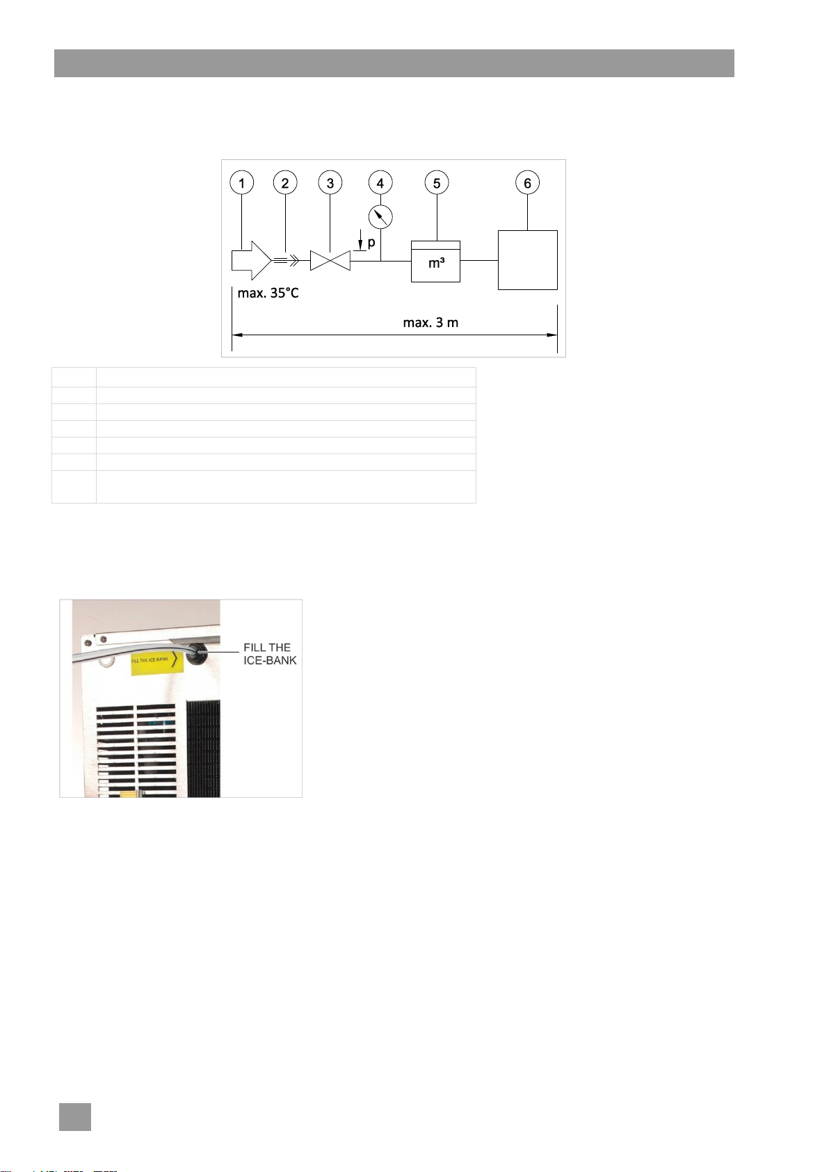
4.1 Requirements--------------------------------------------------------------------------------------------------------------- 5
4.2 Water connection ---------------------------------------------------------------------------------------------------------- 5
4.3 Waste water----------------------------------------------------------------------------------------------------------------- 6
4.4 Gas connection------------------------------------------------------------------------------------------------------------- 7
4.5 Electrical connection ------------------------------------------------------------------------------------------------------ 8
5Commissioning ----------------------------------------------------------------------------------------------------------- 9
5.1 Prerequisites---------------------------------------------------------------------------------------------------------------- 9
5.2 Fill the ice-bank water bath---------------------------------------------------------------------------------------------- 9
5.3 Installing the dummy plug------------------------------------------------------------------------------------------------ 9
5.4 Adding tablets to prevent the formation of algae into the ice-bank water bath-----------------------------10
5.5 Setting the water pressure----------------------------------------------------------------------------------------------10
5.6 Setting the gas pressure reducer -------------------------------------------------------------------------------------10
5.7 Venting the carbonator tank--------------------------------------------------------------------------------------------10
5.8 Removing the pressure gauge-----------------------------------------------------------------------------------------10
5.9 Perform hygiene maintenance-----------------------------------------------------------------------------------------11
6Hygiene maintenance--------------------------------------------------------------------------------------------------11
7Setting the water dispenser------------------------------------------------------------------------------------------15
7.1 Setting the flow regulator for carbonated water -------------------------------------------------------------------15
7.2 Setting the portion sizes-------------------------------------------------------------------------------------------------16
7.3 Setting the refrigeration--------------------------------------------------------------------------------------------------17
8Maintenance work-------------------------------------------------------------------------------------------------------17
9Descaling the water outlet pipe-------------------------------------------------------------------------------------18
9.1 Removing the water outlet pipe ---------------------------------------------------------------------------------------18
9.2 Descaling the water outlet pipe----------------------------------------------------------------------------------------18
9.3 Installing the water outlet pipe-----------------------------------------------------------------------------------------18
10 Replacing the water outlet pipe with UVC lamp---------------------------------------------------------------19
11 Renew water bath -------------------------------------------------------------------------------------------------------19
12 Water clock----------------------------------------------------------------------------------------------------------------20
12.1 Inserting the batteries----------------------------------------------------------------------------------------------------20
12.2 Setting the capacity ------------------------------------------------------------------------------------------------------20
12.3 Displaying the remaining capacity------------------------------------------------------------------------------------20
12.4 Reset-------------------------------------------------------------------------------------------------------------------------20
12.5 Changing the batteries --------------------------------------------------------------------------------------------------20
13 Decommissioning the water dispenser--------------------------------------------------------------------------21
14 Malfunctions--------------------------------------------------------------------------------------------------------------22
15 Safety inspection--------------------------------------------------------------------------------------------------------23
15.1 Check relief valve---------------------------------------------------------------------------------------------------------23
15.2 Check for leaks------------------------------------------------------------------------------------------------------------23
16 Technical data------------------------------------------------------------------------------------------------------------24
17 Circuit diagram-----------------------------------------------------------------------------------------------------------25
18 Flow schema--------------------------------------------------------------------------------------------------------------26

About this manual
2
1 About this manual
This manual is intended exclusively for the use by service technicians authorised by EauVation.
The following symbols are used in these instructions:
Symbol
Meaning
Danger
Warning of potentially serious or fatal injuries to persons if the described precautionary
measures are not taken.
Warning
Warning of potentially minor injuries to persons or potential material damage if the described
precautionary measures are not taken.
Caution
Warnings of possible defects or damage to the product if the described precautionary
measures are not followed.
IMPORTANT
Important information is provided here.
INFO
Useful information is given here.
This symbol indicates instructions.
This symbol indicates results of actions.
This symbol indicates itemisations.
This symbol refers to a chapter with more detailed information.
2 Safety notes
2.1 General safety notes
Warning
Risk of injury from sharp-edged plates and chemicals
Wear protective gloves for all maintenance and repair work.
Wear protective clothing, protective gloves and protective goggles when dealing with chemicals.
Never insert or pull out the plug with wet hands.
Never remove the plug from the socket using the cord.
Do not look directly into the water outlet and the UVC lamp behind it.
2.2 Carbonic acid bottle
Danger
Danger of suffocation by carbon dioxide
Carbon dioxide (CO2) is a colourless and odourless gas and, at high concentrations in
the air, leads to suffocation.
Outflowing carbon dioxide is heavier than air. A risk of suffocation occurs in the case of a
high accumulation in closed rooms.
Only use the supplied gas hose for the gas connection. For other hoses with the same outside diameter,
the wall thickness may be too low.
The carbonic acid bottles may only be used in combination with a suitable gas pressure reducer (max.
5 bar operating pressure).
Please follow all the instructions in the water dispenser operating instructions for the operation and stor-
age of the carbonic acid bottle.

Device overview / main components
3
2.3 Maintenance and repair work
The plug must be pulled from the power supply for all installation and maintenance work.
Maintenance and repair work may only be performed by service technicians authorised by EauVation.
Inappropriate maintenance or repair work can result in serious risks for the user, for which EauVation
shall not accept liability.
Original spare parts must be used for repairs or to replace consumable parts. If original spare parts are
not used, the warranty is invalidated.
Caution
Possible leakage from improperly cut hoses
Use the hose cutter to ensure the hose cross section remains round and that the hose is
cut straight.
Caution
Possible leakage from damaged hoses
Check the hose. If there are any scores on the hose, shorten the hose or replace it to
ensure a tight plug connection.
3 Device overview / main components
Front view
Rear view
Item
Description
1
Operating panel
2
Water outlet
3
Drip tray with mesh
Item
Description
4
Ice-bank water supply
5
Thermostat (adjustable)
6
Main switch
7
Electrical supply
8
Hose connection for the drip tray
9
Connection for carbonic acid
10
Water connection
11
Ice-bank level indicator
12
Programming button (setting the portioning)
13
Mains cable with plug
14
Water hose / Waste water hose for drip tray
15
Carbonic acid hose

Device overview / main components
4
View from the top
Item
Description
1
Filter head for hygiene filter
2
Vent valve
3
Pump
4
Water bath (under the pump)
5
Flow regulator
6
Button for advanced hygiene maintenance (not implemented yet)
7
Solenoid valve for still and carbonated water
8
Carbonator tank
Hygiene maintenance cleaner
EAUVATION N° 1
Hygiene spray
EAUVATION N° 2
Acid spray cleaner
EAUVATION N° 3
Cleaning tablets for water
bottles and carafes
EAUVATION N° 4

Setup and connection
5
4 Setup and connection
4.1 Requirements
Raw water requirements
The quality of the water at the inlet must fulfil the valid drinking water regulations applicable to the specific
country. In addition, the following threshold limits must be adhered to (16).
Installation site requirements
Frost free
Well ventilated, clean, dry
Firm, level surface for the water dispenser
No sources of heat next to the water dispenser
See Chapter 16 for space requirements and minimum clearance from the wall.
The water shut-off valve and the water dispenser must not be more than 3 m distance from one another.
Stagnant water in long hoses can lead to contamination.
Minimum room size to prevent a hazardous concentration of carbon dioxide (please see table).
Carbonic acid bottle
Minimum room size (with approx. 10 % furniture)
Room height: min. 2.5 m
2 kg
15 m²
3 kg
22.5 m²
5 kg
37.5 m²
6 kg
45 m²
10 kg
75 m²
IMPORTANT A gas alarm device must be installed if the room is less than the minimum room size.
Alternative: 2-fold air exchange within 24 hours (continuous exchange of air).
If the water dispenser and the carbonic acid bottle are located in different rooms, the
minimum room size shall apply to both rooms.
4.2 Water connection
Warning
Possible contamination
The water stop cock and the water dispenser must not be more than 3 m distance
from one another. Stagnant water in long hoses can lead to contamination.
Only use the supplied water hose for the water connection.
Caution
Possible leakage from improperly cut hoses
Use the hose cutter to ensure the hose cross section remains round and that the hose is
cut straight.
Required materials
Reduction 3/4” or 3/8”
Pressure reducer
Water clock
Water hose
Pressure gauge
Dummy plug
Locking clip
Hygiene spray
EAUVATION N° 2
Hose cutter

Setup and connection
6
Installation diagram
Install the pressure reducer (3) and water clock (5) easily accessible to a wall or in kitchen cabinet. Do not
yet plug in any hoses between the components.
Item
Description
1
Water supply (max. 35 °C)
2
Reduction 3/4” or 3/8”
3
Pressure reducer
4
Pressure gauge with T-piece (installed temporarily)
5
Water clock
6
Acqua 80
IMPORTANT: Do not insert the hygiene filter yet.
Wash hands, put on protective gloves and spray with EAUVATION N° 2.
Connect hoses to all the components. Before inserting the hoses, spray the end of the hoses with
EAUVATION N° 2. Do the same for the hose connections of the components.
The pressure gauge is removed again later. Therefore, the hose between the pressure gauge and the
water clock must be sufficiently long.
Insert the water connection hose into the
“FILL THE ICE-BANK” connection.
All connectors must be secured with locking clips.
Setting the water clock
Set 8000 l water volume (12).
4.3 Waste water
The drip tray can be connected to the waste water.
Waste water connection requirements:
Trap
Level lower than the drip tray
Hose to the waste water connection has a steady gradient to ensure no backlog of water

Setup and connection
7
4.4 Gas connection
Caution
Possible discharge of carbonic acid
The gas connection must always be performed by an instructed service technician.
National guidelines must be observed.
Secure the carbonic acid bottles to prevent them from falling over by using the sup-
plied securing strap. If a bottle is not standing up, the liquid carbonic acid ices up the
gas pressure reducer and puts it out of operation.
Only use the supplied gas hose for the gas connection. For other hoses with the same
outside diameter, the wall thickness may be too low.
Caution
Possible leakage from improperly cut hoses
Use the hose cutter to ensure the hose cross section remains round and that the hose is
cut straight.
Required materials
Strap for carbonic
acid bottle
Gas pressure re-
ducer with safety
valve and pressure
gauges
Shut-off valve
Gas hose
Locking clip
Hose cutter
Before installation
Check whether the following conditions are met:
Carbonic acid bottle available and sealed tightly.
Carbonic acid is of food quality grade (E290 marking).
Size of the room matches the size of the carbonic acid bottle (4.1).
Gas pressure reducer is approved up to 5 bar: see red marking on the operating pressure gauge.
Seal is present and undamaged in the union nut of the gas pressure reducer.
Installation diagram
Item
Description
1
Carbonic acid bottle
2
Gas pressure reducer
3
Shut-off valve
4
Acqua 80
Place the carbonic acid bottles in an upright position.
Secure the carbonic acid bottles to prevent them from falling over by using the supplied securing strap.

Setup and connection
8
Open the valve of the carbonic acid bottle and check whether carbonic acid leaks as gas (not in liquid
form).
Close the valve of the carbonic acid bottle.
Screw the gas pressure reducer tightly to the valve of the carbonic acid bottle using a suitable open-end
spanner.
Connect a shut-off valve to the gas pressure reducer with a short hose (approx. 100 mm).
Close the shut-off valve.
Connect the water dispenser and the water shut-off valve with a hose.
All connectors must be secured with locking clips.
Do not yet open the valve of the carbonic acid bottle.
Point out to the operator that he/she is responsible for the following:
The room in which the water dispenser and the carbonic acid bottle are placed must be sufficiently
large (4.1). If the room is too small: ensure adequate ventilation or have a gas detector installed.
Access to this room must be marked with the warning signs W18 with additional text and W029.
Create a safety risk assessment.
Place a sign where the carbonic acid bottle is placed about the maximum size of the bottle.
Keep a logbook.
W18
Additional text
W029
4.5 Electrical connection
Danger
Connection only to alternating current via correctly installed earthed socket.
Maximum fuse protection: 16 A
Installation must be in accordance with the rating plate.
Install a residual current circuit breaker with a release current of 30 mA in the electrical
feeder.
Caution
The device must remain switched on permanently.
Plug the mains cable into the device and the on-site socket.

Commissioning
9
5 Commissioning
IMPORTANT The hygiene filter may be installed only after the hygiene maintenance (6) to avoid de-
stroying it.
Caution
Damage as the result of leaking water
Adhere to the following sequential order during commissioning:
Fill the water bath of the ice-bank (5.2)
Install the dummy plug (5.3)
5.1 Prerequisites
Gas and water connection in accordance with chapter 4.
Electrical connection in accordance with chapter 4.
The water stop cock is closed.
The valve on the carbonic acid bottle is closed.
The shut-off valve after the gas pressure reducer is closed.
The water dispenser is switched off.
5.2 Fill the ice-bank water bath
Open the water stop cock.
Fill the water bath to a level between MIN and MAX.
Use a cable tie to fix the level indicator hose in place.
Close the water stop cock.
Insert the water connection hose into the “IN H2O” connection.
Before inserting the hose, spray the end of the hose with
EAUVATION N° 2.
5.3 Installing the dummy plug
Pull out the mains plug.
Unscrew the upper cover plate and remove it.
Remove the bracket (1).
Spray the inside of the filter head (3) with EAUVATION N° 2.
Spray the dummy plug (4) with EAUVATION N° 2 and screw
into the filter head (3).
Close the lever at the filter head (turn to the right).
Install the bracket (1).

Commissioning
10
5.4 Adding tablets to prevent the formation of algae into the ice-bank water bath
Using curved needle-nose pliers, add one tablet to prevent the formation of algae to the water bath.
Screw the upper panel tight.
Plug in the mains plug.
5.5 Setting the water pressure
Open the water stop cock.
Set the static pressure to maximum 3 bar at the pressure regulator.
Consequences of too high water pressure
Overfilling of the carbonator tank.
Water supply valve will not open, the pump runs dry and stops after 4 minutes.
Restarting the pump: Pull the plug and plug back in after 3 seconds.
5.6 Setting the gas pressure reducer
Gas pressure reducer
Close the shut-off valve after the gas pressure reducer.
Open the set screw (3) by turning it anti-clockwise.
The spring inside will release.
Slowly open the valve on the carbonic acid bottle.
The pressure gauge (2) shows 0 bar.
Turn the set screw (3) in clockwise direction until the pressure gauge (2) indicates 3.5 - 3.8 bar. The
pressure must be at least 0.5 bar higher than the static water pressure.
5.7 Venting the carbonator tank
Fully open the valve on the carbonic acid bottle.
Pull the mains plug.
Unscrew the upper cover plate and remove it.
Hold the vent valve out of the water dispenser.
Slowly open the shut-off valve on the gas pressure reducer.
Pull 3-4 times on the vent valve to let the air escape from the carbonator tank.
Place the valve vent back into the water dispenser.
Note: The hose and the vent valve may not touch the ventilator.
Screw the upper cover tight.
5.8 Removing the pressure gauge
Plug in the mains plug. Turn on the water dispenser.
Draw approx. 1000 ml of still water and dispose of it.
Read the pressure gauge: the flow pressure should be at least 1.5 bar.
Remove the pressure gauge.
Before plugging in, spray the hose end with EAUVATION N° 2.
Item
Description
1
High pressure side
(carbonic acid bottle)
2
Manometer (operating pressure = pres-
sure after the pressure reducer)
3
Adjusting screw
Clockwise rotation increases the pressure
4
Manometer
(pressure in the carbonic acid bottle)
5
Low-pressure side (connection for the
carbon dioxide hose)

Hygiene maintenance
11
5.9 Perform hygiene maintenance
(6)
6 Hygiene maintenance
Warning
Danger of chemical burn
Cleaning agents can cause severe chemical burns.
Wear protective clothing, protective gloves and protective goggles.
Set up a warning sign during hygiene maintenance, warning of the water release.
Do not use drinking glasses / cups for the hygiene maintenance.
Dispose of drawn water when it is no longer required for the measurement.
Observe the following during hygiene maintenance:
Clean working clothes
Wash your hands
Keep spraying hands / protective gloves with EAUVATION N° 2
Required materials
Protective gloves
Protective goggles
EAUVATION N° 1
EAUVATION N° 2
EAUVATION N° 3
EAUVATION N° 4
Sterile hygiene filter
Maintenance cartridge
Dummy plug
Chlorine test strip
Hose cutter
Water hose (approx. 300 mm long)
Flat-blade screwdriver
Phillips head screwdriver
0.2 l and 1.0 l measuring cup
Bucket (10 l)
Preparation
Wash hands.
Put on protective clothing.
Put on protective gloves and spray with EAUVATION N° 2.
Put on protective goggles.
Draw a sterile water sample. Label water sample and refrigerate. Water sample must reach laboratory
within 24 hours.
Note: Only draw water sample if agreed upon with customer.
Check the water clock: How much water has been drawn since the last maintenance?
The hygiene filter has a capacity of 8300 litres or a service life of six months. Hygiene maintenance
should be performed earlier if more than 8300 litres of water have been drawn during the last six months.
Close the water stop cock.
Depressurise the water pipe by pressing the button for still water.
Turn off the water dispenser.
Pull the mains plug.
Unscrew the upper cover plate and remove it.
Set flow regulator to “Maximum” (7.1).
Checking the water outlet pipe
Check whether the water outlet pipe is calcified. If required, descale (9).

Hygiene maintenance
12
Replacing the hygiene filter with dummy plug (not for first commissioning)
Remove the bracket (1) with hygiene filter (2).
Remove the hygiene filter (2).
Spray the inside of the filter head (3) with EAUVATION N° 2.
Spray the dummy plug (4) with EAUVATION N° 2 and screw
into the filter head (3).
Close the lever at the filter head (turn to the right).
Install the bracket (1).
Screw the upper panel tight.
Plug in the mains plug.
Installing the maintenance cartridge
For the hygiene maintenance, the entire system is flooded with the maintenance cleaner EAUVATION N° 1.
For a thorough cleaning, it is important that the cleaning agent enters the cycle as early as possible. There-
fore, the maintenance cartridge must be installed directly after the water stop cock.
before
after
Insert the cartridge head (3) between the water stop cock (1) and the pressure reducer (2).
Before inserting the hoses, spray the end of the hoses with EAUVATION N° 2. Also spray the hose con-
nections at the cartridge head (3).
Fill 300 ml of maintenance cleaner EAUVATION N° 1 into the maintenance cartridge (4).

Hygiene maintenance
13
Let the maintenance cleaner act
Turn on the water dispenser.
Open the water stop cock.
Draw still water until a pressure shock occurs.
Dispose of water.
Draw approx. 100 ml of still water. When drawing the water, hold a chlorine test strip into the water. As
soon as the colour changes from white to purple, the maintenance cleaning agent has come through.
Dispose of water.
Draw carbonated water. When drawing the water, hold a chlorine test strip into the water. As soon as the
colour changes from white to purple, the maintenance cleaning agent has come through.
Dispose of water.
Let the cleaning agent act for approx. 5 minutes. Draw approx. 50 ml of each water type in between.
Rinse the maintenance cleaning agent
Draw approx. 10 l of each water type and dispose of it. When drawing, alternate between the two water
types.
Draw approx. 200 ml of each water type.
Using the chlorine test strip, check whether the water still contains maintenance cleaner (colour changes
white -> purple).
Dispose of water.
Keep drawing water from both water types until the colour no longer changes.
Close the water stop cock.
Depressurise the water pipe by pressing the button for still water.
Turn off the water dispenser.
Pull the mains plug.
Removing the maintenance cartridge
before
after
Removing the maintenance cartridge (3+4).
Spray the hose end (1) with EAUVATION N° 2. Also spray the hose connection at the pressure reducer (2).
Plug the hose (1) into the pressure reducer (2).
IMPORTANT Check the end of the hose. If there are any scores on the hose, shorten the hose or re-
place it to ensure a tight plug connection.

Hygiene maintenance
14
Installing the hygiene filter
Turn off the water dispenser.
Pull out the mains plug.
Unscrew the upper cover plate and remove it.
Remove the bracket (1) with hygiene filter (2).
Remove the dummy plug (2).
Spray the inside of the filter head (3) with EAUVATION N° 2.
Insert a new sterile hygiene filter (1) into the filter head (2).
Before inserting the filter, spray the plug connection of the
hygiene filter with EAUVATION N° 2.
IMPORTANT Do not touch the plug connection of the hy-
giene filter (hygiene).
Close the lever at the filter head (turn to the right).
Install the bracket (1).
Set the flow meter (7.1).
Screw the upper cover tight.
Plug in the mains plug.
Turn on the water dispenser.
Open the water stop cock.
Draw approx. 2 litres of still water and dispose of it.
Draw approx. 2 litres of carbonated water and dispose of it.
This will wet the hygiene filter.
Finalisation
Spray protective gloves with EAUVATION N° 2.
Draw a sterile water sample. Label water sample and refrigerate. Water sample must reach laboratory
within 24 hours.
Note: Only draw water sample if agreed upon with customer.
Clean the drip tray.
Clean the outside of the water dispenser with EAUVATION N° 3.
IMPORTANT Do not wipe the water outlet as this may cause germ contamination.

Setting the water dispenser
15
7 Setting the water dispenser
7.1 Setting the flow regulator for carbonated water
The amount of water which is drawn per unit of time is set on the flow regulator (1).
Factory setting: 200 ml in 8 seconds (1.5 l/min = 150 ml/6 s)
Clockwise rotation: Flow rate is reduced
Anti-clockwise rotation: Flow rate is increased
IMPORTANT After each hygiene maintenance, the flow rate must be reset correctly. If the flow rate is too
high, the carbonator tank will run empty. The pump will stop after 4 minutes to prevent it
from running dry. Restarting the pump: Pull the plug and plug back in after 3 seconds.
Completely close the flow regulator (1) (clockwise rotation).
Open the flow regulator (1) with 2 rotations.
Draw carbonated water and test it:
Does approx. 200 ml of water flow out in 8 seconds?
Is the carbonation of the water correct?

Setting the water dispenser
16
7.2 Setting the portion sizes
Each button can be set to how much water should flow when pressing the button.
Factory setting:
Button 3 and 4: 0.2 l
Button 2 and 5: 0.7 l
Setting the programming mode
Press buttons (1), (4) and (5) at the same time until the background lighting flashes and a beeping sound
can be heard.
Release all buttons.
Setting the portion sizes
Still water, small portion
Briefly press button (4).
Press button (4) again as soon as the portion size is correct.
Still water, large portion
Briefly press button (5) and release it as soon as the water comes.
Press button (5) again as soon as the portion size is correct.
Carbonated water, small portion
Briefly press button (3).
Press button (3) again as soon as the portion size is correct.
Carbonated water, large portion
Briefly press button (2) and release it as soon as the water comes.
Press button (2) again as soon as the portion size is correct.
Exiting programming mode
Press buttons (1), (4) and button (5) at the same time until the background lighting no longer flashes and
a beeping sound can be heard.
Release all buttons.

Maintenance work
17
7.3 Setting the refrigeration
(1): Thermostat
Clockwise rotation: Temperature is lowered
Anti-clockwise rotation: Temperature is increased
If larger volumes of cooled water are regularly drawn:
Set the thermostat to 6 so that an ice-bank can form.
8 Maintenance work
Scope of work
Interval
Hygiene maintenance (6)
every 6 months
Replacing the hygiene filter (6).
every 6 months
Checking the water outlet pipe for scaling.
If required, descale (9).
every 6 months
Replacing the water outlet pipe with UVC
lamp (10).
every 12 months
Add tablet to the ice-bank water bath to
prevent the formation of algae (5.3).
every 12 months
Check the fill level of the water bath; refill if
required (11).
every 12 months
Drain the water bath and refill.
every two years
Safety inspection (15)
every 2 years

Descaling the water outlet pipe
18
9 Descaling the water outlet pipe
Water outlet pipe
9.1 Removing the water outlet pipe
Warning
Risk of injury from broken glass in the water
Part of the water outlet pipe is made of glass. During removal or installation, only pull or press
the metal pipe. Make sure the glass pipe is not damaged before installation.
9.2 Descaling the water outlet pipe
Dissolve one tablet of EAUVATION N° 4 in 20 ml of water in a small
measuring cup.
Hold the calcified end of the pipe into the solution.
IMPORTANT Do not fully immerse the water outlet pipe in the solu-
tion. The descaler will attack the UVC lamp and alu-
minium.
9.3 Installing the water outlet pipe
Installation in reverse order.
Check whether the water jet comes out straight. If necessary, correct.
Item
Description
1
Metal pipe
2
Glass sheet
3
UVC lamp
Table of contents