EAW VRM12 User manual

INSTRUCTION MANUAL
VRM12
Two-Way, Full-Range Stage Monitor/PA

2 – VRM12
VRM12 – 3
1. SAFETY INSTRUCTIONS
1. Read these instructions.
2. Keep these instructions.
3. Heed all warnings.
4. Follow all instructions.
5. Do not use this apparatus near water.
6. Clean only with a dry cloth.
7. Do not block any ventilation openings. Install in accordance with the manufacturer’s instructions.
8. Do not install near any heat sources such as radiators, heat registers, stoves, or other apparatus
(including ampliers) that produce heat.
9. Only use attachments/accessories specied by the manufacturer.
10. Refer all servicing to qualied service personnel. Servicing is required when the apparatus
has been damaged in any way, such as liquid has been spilled or objects have fallen into the
apparatus, the apparatus has been exposed to rain or moisture, does not operate normally, or has
been dropped.
11. The entire sound system must be designed in compliance with the current standards and laws
regarding electrical systems.
12. When installing and using this apparatus, keep in mind the technical specications indicated in the
dedicated section of the manual.
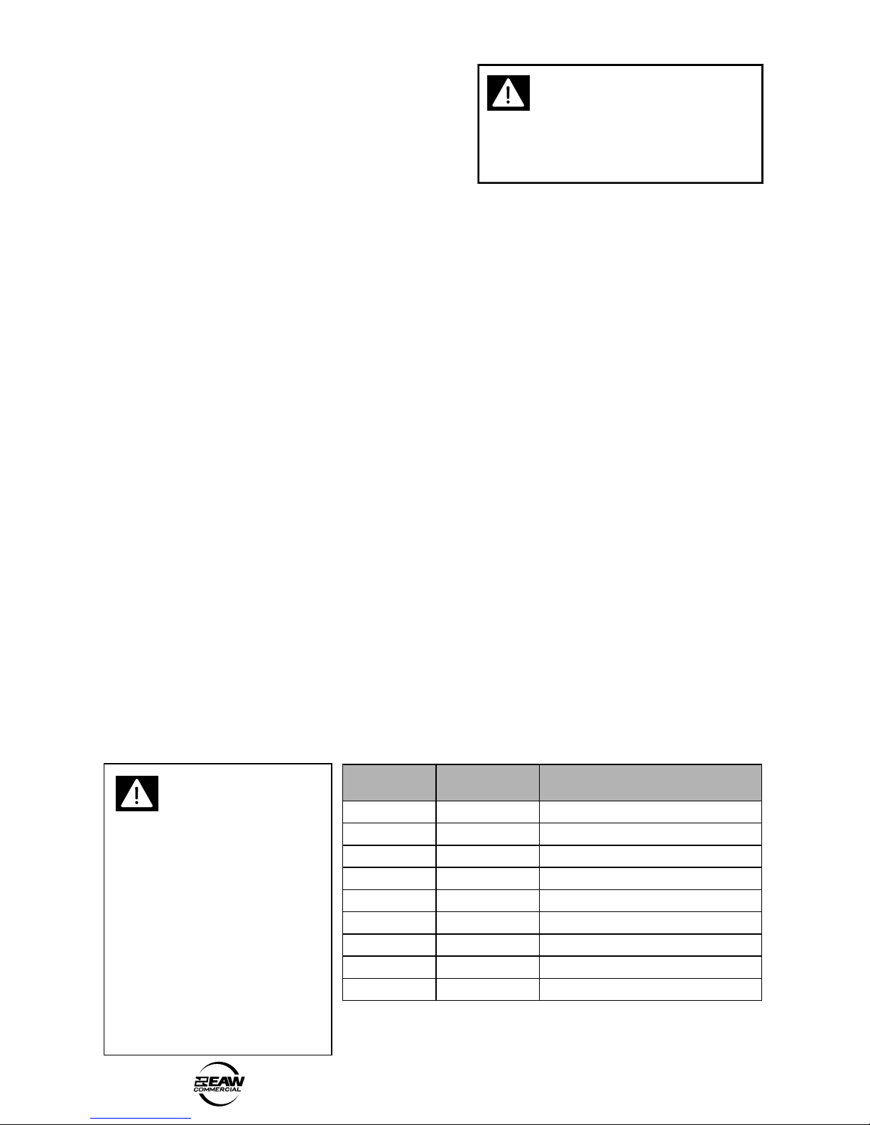
13. Exposure to high sound levels can cause permanent hearing loss. The sound pressure level which
leads to hearing loss varies considerably from one person to another, and depends on the duration
of exposure. The U.S. Government’s Occupational Safety and Health Administration (OSHA) has
established the maximum sound pressure levels that can be with stood without causing damage,
which are shown in the table below. According to the OSHA regulations, any exposure over the
maximum limits indicated in the table can reduce the hearing capacity of a person. To prevent
potentially dangerous exposure to high sound pressure levels, anyone subjected to such levels
must use suitable protection. When a EAW Commercial product capable of producing high sound
levels is being used, it is therefore necessary to wear ear plugs or protective earphones when
the limits shown in the table are exceeded. Consult the specications provided in the instruction
manual to know the maximum sound pressure (SPL) the loudspeaker is capable of producing.
WARNING! This
equipment has been
designed to be installed
by qualied professionals
only! There are many factors
to be considered when
installing professional sound
reinforcement systems,
including mechanical and
electrical considerations, as
well as acoustic coverage and
performance. EAW Commercial
strongly recommends that this
equipment be installed only by
a professional sound installer or
contractor. Part No. 0012178 Rev.A 10/04
© 2004 LOUD Technologies Inc. All Rights Reserved.
repnoitaruD
)sruoh(yad
leveldnuoS
)ABd( elpmaxelacipyT
8 09 bulcllamsaniouD
6 2
9
4 59 n
iartyawbuS
3 7
9
2 0
01 cisumlacissalcduolyreV
5.1 201
1 5
01 teef05taevitomocoL
5.0 011
sselro52.0 511 trecnockcoratastraptseduoL
The exclamation point within an
equilateral triangle is intended to
alert the user of the presence of
important operating and maintenance
(servicing) instructions in the literature
accompanying the apparatus.

2 – VRM12
VRM12 – 3
14. Rigging Precautions: When mounting or suspending EAW Commercial loudspeaker
enclosures, it is essential that load ratings, rigging techniques, and special safety
considerations be appropriate for the installation. Use only the mounting/rigging points
on the loudspeaker enclosure intended for this purpose. The user must determine the load
requirements, dynamic loading, and any other contributing factors affecting the loudspeaker
installation. The user must determine the proper design factor for specic applications and
the required load rating of the connection to structure. Comply with all applicable federal,
state, and local regulations.
EAW Commercial strongly recommends the following rigging system practices:
• Documentation: Thoroughly document the mounting/rigging design with detailed
drawings and parts lists.
• Analysis: Have a licensed structural engineer or other qualied professional review and
approve the mounting/rigging design before its implementation.
• Installation: Use personnel experienced and qualied for mounting/rigging loudspeakers
in accordance with and in compliance with all federal, state and local regulations.
DANGER: Loudspeakers should be mounted or suspended only by persons with knowledge
of the proper hardware and rigging techniques. When stacking or pole-mounting
loudspeakers, be sure that they are stabilized and secured from falling over or being
accidentally pushed over. Failure to follow these precautions may result in damage to the
equipment, personal injury, or death.
TABLE OF CONTENTS
1. SAFETY INSTRUCTIONS........................................................ 2
2. INTRODUCTION....................................................................... 4
3. INSTALLATION ........................................................................ 5
4. CONNECTIONS........................................................................ 6
5. OPERATION.............................................................................. 9
6. SPECIFICATIONS..................................................................... 10
Dimensions.............................................................................. 10
Performance Graphs .............................................................. 11
7. TROUBLESHOOTING .............................................................. 12
8. SERVICE and MAINTENANCE............................................... 13
9. WARRANTY ............................................................................. 15

4 – VRM12
VRM12 – 5
2. INTRODUCTION
Congratulations on the purchase of your new EAW Commercial loudspeaker. You now
own one of the nest professional audio products available – the result of exceptional
engineering and meticulous craftsmanship. Please read these instructions to get the
maximum performance from your new loudspeaker.
Each EAW Commercial loudspeaker is intended for professional use. The construction,
components, and hardware have been designed to provide robust, reliable performance for
its intended application. Please ensure that you fully understand its proper installation and
operation before use.
This manual describes the VRM12 passive two-way stage monitor/PA. The VRM12 is
engineered for superior performance as a oor monitor, and as a stand-mounted portable
PA speaker. The low-prole, dual-angle enclosure houses a 12-inch coaxial driver that cuts
through stage volume with high output capability. Coherent point-source reproduction helps
deliver crisp speech for meetings and presentations, while the 12-inch LF driver delivers full-
range musical sound.
The cross-ply laminated birch enclosure includes loop-thru Neutrik NL4 Speakon jacks on
either side to minimize cable runs and clutter on stage. Rubber feet stabilize the enclosure
on the oor. A pole-mount cup and integral handle are included for stand-mounting and
transport.
The VRM12 is available in either black or white nish. A foam-backed powder-coated
steel grill protects the driver.
Features:
• Full-range, 2-way loudspeaker
• Coaxial 12-inch woofer with
1-inch exit compression driver
• Protection circuit for
compression driver
• Passive crossover for
economical, single-amplier
operation
• Enclosure has 30 degree and
45 degree wedge angles
• Pole-mount cup allows pole
mounting and use as a portable
PA
• Spring-loaded handle for ease of
handling
• Two Speakon jacks with input
and through connections
• Five-year warranty
Applications include:
• TV studios
• Theaters
• Portable PA
• Classrooms
• Houses of Worship
• Audio-visual Presentations
• Performing Arts

4 – VRM12
VRM12 – 5
3. INSTALLATION
Unpacking and Inspection
Visually inspect the outside of the shipping carton and check for any shipping damage.
After unpacking, if you nd concealed damage to the loudspeaker, save the packing materials
for the carrier’s inspection, notify the carrier immediately, and le a shipping damage claim.
Although EAW Commercial will help in any way possible, it is always the responsibility of
the receiving party to le any shipping damage claim. The carrier will help prepare and le
this claim.
Mounting Precautions
The loudspeaker is tted with rubber feet for isolated positioning on stage. It can be
mounted so the front grille face is tilted at 45 degrees, or at 30 degrees.
The loudspeaker also has a pole-mount insert (1.5-inch diameter), allowing it to be pole-
mounted for PA applications.
WARNING: Installation should only be done by an experienced technician.
Improper installation may result in damage to the equipment, injury or death. Make
sure that the loudspeaker is installed in a stable and secure way in order to avoid any
conditions that may be dangerous for persons or structures:
• Check to make sure that the support surface (e.g., oor, etc.) has the necessary
mechanical characteristics to support the weight of the loudspeaker and pole-mount
without the danger of it falling.
• When pole-mounting loudspeakers, be sure that they are stabilized and secured from
falling over or being accidentally pushed over. Failure to follow these precautions
may result in damage to the equipment, personal injury, or death.
• Never use the handle for supporting or ying the loudspeaker.
• Avoid installing the loudspeaker in places exposed to harsh weather conditions.

6 – VRM12
VRM12 – 7
4. CONNECTIONS
WARNING: To prevent the risk of electric shock, do not connect the loudspeaker
with the amplier switched on.
The loudspeaker has two identical Speakon connectors, which are wired as follows:
Inputs:
• Pin 1+ is the positive (+) input,
and connects to the positive (+)
output of your power amplier.
• Pin 1– is the negative (–) input,
and connects to the negative
(–) output of your power
amplier.
• Pin 1+ and 1– of one Speakon are connected internally to the VRM12 crossover’s
input. They are also connected internally to Pin 1+ and 1– of the other Speakon,
which can be used to send speaker-level power to another VRM12.
Through Outputs:
• Pin 2+ is the positive (+) through output.
• Pin 2– is the negative (–) through output.
• Pin 2+ and 2– are not connected internally to the VRM12 crossover’s input. They are
only connected internally to Pin 2+ and 2– of the other Speakon.
Connection Examples:
• Using the second Speakon (Pin 1+,1-) to connect a second VRM12 in parallel.
Make sure that the total average impedance of your loudspeakers does not drop
below the recommended minimum load impedance of your power amplier.
For example, when two VRM12s are wired as shown above, the total average
impedance is 4 ohm. For three VRM12s, the total average is 2.67 ohm. Make sure
your amplier can handle this load impedance, or it may become overloaded.
xover
VRM12 enclosure
Pin
Speakon Speakon
Pin
1+
1-
2+
2-
1+
+
++
1-
2+
2-
xover
VRM12 enclosure
Pin
Speakon Speakon
Pin
1+
1-
2+
2-
1+
+
++
1-
2+
2-
A+
Amp
xover
VRM12 enclosure
Pin
Speakon Speakon
Pin
1+
1-
2+
2-
1+
+
++
1-
2+
2-
2-conductor cable

6 – VRM12
VRM12 – 7
• Using the Pin 2+,2- Speakon connections to connect the second power amplier
channel to a subwoofer.
• Using the Pin 2+,2- Speakon connections to connect the second power amplier
channel to a second VRM12. You will need a cross-wired cable which has Pins 2 at
one end connected to Pins 1 at the other.
Loudspeaker Cables
• Use loudspeaker cables with a minimum conductor size for the length you need,
as listed in these tables. This will minimize
power losses to less than 0.5 dB. The
cable lengths listed are “up to” lengths.
For in-between lengths, use the next larger
conductor gauge. Using larger than the
recommended conductor size is always
permissible. Using smaller than recommended
conductor size will result in higher power
losses.
• The recommended conductor gauges are
listed for AWG (American Wire Gauge) and
Metric WG (Metric Wire Gauge). Note that
smaller AWG numbers = larger conductors
and smaller Metric WG numbers = smaller
conductors. The Metric WG is equal to ten
times the nominal conductor diameter in
millimeters.
• For cable lengths over 200 feet / 60 m at 8 ohms, and over 100 feet / 30 m at 4 ohms,
the conductor sizes needed for less than 0.5 dB power losses are rarely practical
for physical and cost reasons. As a practical compromise for these situations the
recommended conductor gauge is 10 AWG or 25 metric.
Minimum AWG 4 ohm 8 ohm
18 10 ft 25 ft
16 25 50
14 25 75
12 50 125
10 100 200
Min Metric WG 4 ohm 8 ohm
12 3 m 8 m
14 8 15
16 8 25
20 15 40
25 30 60
xover
VRM12 enclosure
Pin
Speakon Speakon
Pin
1+
1-
2+
2-
1+
+
++
1-
2+
2-
xover
VRM12 enclosure
Pin
Speakon Speakon
Pin
1+
1-
2+
2-
1+
+
++
1-
2+
2-
Amp A+
B+
xover
VRM12 enclosure
Pin
Speakon Speakon
Pin
1+
1-
2+
2-
1+
+
++
1-
2+
2-
Sub
Amp A+
B+
4-conductor cable
4-conductor cable
cross-wired cable
Lead Guitar
(for example)
Bass Guitar
(for example)
+

8 – VRM12
VRM12 – 9
Precautions
• To prevent inductive phenomena causing humming or distortion, the speaker cables
should not be run together with electrical energy conductors, microphone cables, or
line-level audio lines.
• Use speaker cables that have markings to distinguish the polarity, such as insulation
or conductors of different colors.
• Before using the loudspeaker, carefully check that all the connections have been
made correctly to make sure there are no accidental short circuits that could cause
electrical sparks.
• Verify that the polarity of the connections to all of your loudspeakers is correct. When
more than one loudspeaker reproduces the same frequencies, but with opposite
polarity, there will be sound cancellations. Therefore, if any of the loudspeakers
are wired so that the +/- connection polarity is reversed with respect to the others,
incorrect reproduction will result. Most notably, the bass response will suffer. This
is especially true when loudspeakers are situated in adjacent positions where the
sound waves readily interact with each other.

8 – VRM12
VRM12 – 9
5. OPERATION
Signal Processing
Sometimes external signal processing is desirable to “voice” the loudspeaker to
accommodate particular program material, less than optimum acoustics, feedback control, or
personal taste. For these purposes, use a suitable electronic signal processor. This can be as
simple as a 1/3 octave graphic equalizer or a fully capable DSP (digital signal processor) such
as the EAW Commercial DX810, or the EAW MX8750.
Choosing a Power Amplier
There is no exact answer to the question of what amplier size you should use for a
loudspeaker. The loudspeaker power rating in EAW Commercial’s specications only means
it has passed a standard power test. This provides a rating that can be used as a point of
comparison with other loudspeakers. This rating does not necessarily correspond to the best
amplier size to use nor is it a measure of a “safe” amplier size to use. Rather, the amplier
should be sized according to both the sound levels required and the type of audio signals
that will be reproduced. If you are unsure of how to determine this, consult with a qualied
professional or contact EAW Commercial Technical Support.
Preventing damage to the loudspeaker is a function of operating your audio system so
that the loudspeaker is not stressed beyond its design limits.
Operating Tips
• Do NOT drive any of your electronic equipment into clipping, particularly the power
ampliers. This can easily damage the loudspeaker.
• If driven into clipping, even an amplier with a power output rating lower than the
loudspeaker’s power rating can cause damage to a loudspeaker.
• Avoid sustained microphone feedback. This can quickly cause failure of high-
frequency drivers.
• Avoid extreme boosts on equalizers as these can cause excessive input to the drivers
at the boosted frequencies. Generally, cutting frequencies is preferred to adjust the
frequency response.
• With appropriate signal processing, your loudspeaker should produce exceptionally
good sound. If it is used in a room with problematic acoustics, there is little you can
do to overcome the room problems with electronic adjustments. Your best solution
is careful placement and aiming of the loudspeaker so most of the sound is directed
only at the audience.
• Most EAW Commercial loudspeakers are capable of sound levels that can be
damaging to human hearing. Take precautions so that audiences are not exposed
to such levels. If you must expose yourself to these kinds of volume levels, wear
adequate hearing protection.
• Take care when moving or lifting the loudspeaker. Injury to you or damage to the
loudspeaker can result from careless handling.

10 – VRM12
VRM12 – 11
7.63"
(193.7)
12.50"
(317.5)
5.94"
(150.9)
15.00"
(381.0)
7.50"
(190.5)
3.94"
(100.1)
15.00"
(381.0)
0.44"
(11.2 mm)
LEFT SIDE FRONT RIGHT SIDE
NOTES:
1. DIMENSIONS ARE IN INCHES, DIMENSIONS IN BRACKETS ARE MILLIMETERS
2. DIMENSION TOLERANCE ± 0.1"
(
2.5 MM
)
6. SPECIFICATIONS
VRM12 Dimensions
Model VRM12
Woofer 12” x 1
Woofer Loading Sealed
Tweeter 1” exit, Compression
Tweeter Loading Horn
Operating Range (–10 dB) 73 Hz – 20 kHz
Horizontal Beamwidth - Nominal 90 degrees
Vertical Beamwidth - Nominal 90 degrees
Axial Sensitivity (whole space SPL) 94 dB, 73 Hz – 20 kHz
Peak Sensitivity (whole space SPL) 97 dB, 20 Hz – 20 kHz
Input Impedance - Nominal 8 ohm
Input Impedance - Minimum 6.6 ohm @ 200 Hz
Recommended High Pass Filter ≥ 60 Hz, 24 dB/octave
Butterworth
Power Handling 300 W, 49 V @ 8 ohms
Maximum SPL, Average 119 dB
Maximum SPL, Peak 125 dB
Height (front face) 15.00”/381 mm
Width (front face) 15.00”/381 mm
Depth (from face, backwards) 12.50”/317.5 mm
Dimension Tolerance ± 0.1”/2.5 mm
Weight 36 lb/16.3 kg
Pole Mount Diameter 1.5”/38.1 mm

10 – VRM12
VRM12 – 11
PERFORMANCE GRAPHS
VRM12 Impedance vs Frequency
VRM12 Axial Response vs Frequency
120
110
100
90
80
70
60
10 100 1000 10k 20k
SPL dB
Fre
q
uenc
y
(
Hz
)
VRM12 Beamwidth vs Frequency
120
110
100
90
80
70
60
360
100
10
1
100
10
1
10 100 1000 10k
10 100 1000 10k
100 1000 10k
20k
20k
20k
dB SPL
Degrees
Frequency (Hz)
Frequency (Hz)
Frequency (Hz)
Ohms
Horizontal
Vertical
120
110
100
90
80
70
60
360
100
10
1
100
10
1
10 100 1000 10k
10 100 1000 10k
100 1000 10k
20k
20k
20k
dB SPL
Degrees
Frequency (Hz)
Frequency (Hz)
Frequency (Hz)
Ohms
Horizontal
Vertical
Disclaimer
EAW Commercial continually engages in research related to product improvement, new
materials, and production methods. Design renements are introduced into existing products
without notice as a routine expression of that philosophy. For this reason, any current EAW
Commercial product may differ in some respect from its published description, but will
always equal or exceed the original design specications unless otherwise stated.
“EAW Commercial” is a trademark of LOUD Technologies Inc.
All other brand names mentioned are trademarks or registered trademarks of their
respective holders, and are hereby acknowledged.

12 – VRM12
VRM12 – 13
7. TROUBLESHOOTING
Loudspeaker difculties usually fall into one of the following categories. The causes for
each are listed in the most likely order of probability.
No Sound or Low Output
• Loudspeaker cables or connectors are not wired correctly or are faulty. Check
all cabling, referring to these instructions for the correct connections. The best
way to check a suspect cable is to swap it with a known good cable. Check the
loudspeaker’s input panel to verify correct cable connections.
• Electronic equipment is not turned on, or the level controls are not adjusted properly.
Make sure that all equipment in the signal path is powered up, and that all controls
are set to appropriate levels for normal operation.
• Loudspeaker is not working. Connect the loudspeaker cable to a known good
loudspeaker, leaving all equipment set to the same levels. If the problem disappears,
the loudspeaker is probably not working. Contact EAW Commercial Technical Support
for appropriate troubleshooting.
Distorted Sound
• The power amplier is clipping. The signal level is exceeding the limits of your
system and you must reduce the level.
• Other electronic equipment is being overdriven. Ensure that no equipment in the
signal chain is being over driven. For example: input(s) or summing bus in the mixing
console, equalizers, etc.
• Driver(s) not working properly. Contact EAW Commercial Technical Support for
appropriate troubleshooting.
Partial Sound (frequency band missing)
• Incorrect EQ settings in the electronic equipment. Ensure that all EQ settings and
lters on the mixing console, preamplier, or other equipment are set for normal
operation. Ensure that level controls on electronic crossovers and associated
ampliers are correctly set, and that all cables and connections for such equipment
are connected and working properly.
• Driver not working properly. Contact EAW Commercial Technical Support for
appropriate troubleshooting.
• The crossover network inside the loudspeaker is not working properly. Contact EAW
Commercial Technical Support for appropriate troubleshooting.

12 – VRM12
VRM12 – 13
8. SERVICE and MAINTENANCE
Maintenance
Usually, your EAW Commercial loudspeaker will not require regular maintenance for
normal use. However, you can do several things to keep your loudspeaker in good operating
and cosmetic condition.
• Testing: Periodically test your loudspeaker for proper performance. A simple test is
to play a CD through it using well-dened, articulate, wide-range program material.
Listen to ensure all drivers are working properly and for any evidence of distortion or
other extraneous sounds. Test at several volume levels: very low, normal, and high.
• Mounting/Rigging: Any mounting or rigging hardware should be regularly inspected
for security, wear, deformation, corrosion, and any other circumstances that may
affect the load-handling capability. Immediately remove from service and replace any
hardware whose load-handling capability may be compromised.
• Cleaning: Cleaning the exterior of the enclosure will depend on the type of “dirt.”
Dust, food spills, or similar contaminants can usually be removed with a cloth
dampened with water, or a mild household cleaner. Avoid using any strong solvents
as this may damage the nish. Turn the ampliers off before cleaning.
• Scratches or Dents in Wood Enclosures: Minor scratches on the enclosure can be
painted over with an outdoor latex paint, or simply a colored in with a “Sharpie” or
artist’s marking pen. More serious gouges or dents should be sanded out, lled with
wood putty, and repainted. Touch-up paint in pints and quarts is available through
EAW Commercial Technical Support.

14 – VRM12
VRM12 – 15
Service
If your loudspeaker should require servicing, please follow these instructions:
1. Call EAW Commercial Tech Support at 1-888-337-7404, 7 am to 5 pm PST
(Monday-Friday), to verify the problem and obtain a Service Request Number. Be sure
to have the serial number of the unit when you call. You must have a Service Request
Number in order to obtain warranty service at the factory or at an authorized service
center. You can also email EAW Commercial Tech Support at:
2. Pack the unit in its original packaging. THIS IS VERY IMPORTANT. LOUD Technologies
is not responsible for any damage that occurs during shipping due to non-
conventional packaging. Original packaging helps to minimize the possibility of
shipping damage.
3. Include a legible note stating your name, (no P.O. boxes), daytime phone number,
Service Request Number, and a detailed description of the problem, including how
we can duplicate it.
4. Write the Service Request Number in BIG BOLD PRINT on top of the box.
5. Tech Support will tell you where to ship the unit when you call for a Service Request
Number. We suggest insurance for all forms of cartage.
EAW Commercial Technical Support
Phone (USA/Canada) 888-337-7404
Phone 425-892-6503
Fax 425-485-1152
Address One Main Street
Whitinsville, MA 01588
Web site www.eawcommercial.com

14 – VRM12
VRM12 – 15
9. WARRANTY
Warranty: LOUD Technologies Inc. requires its authorized EAW Commercial distributors
abide by the following warranty terms for all EAW Commercial brand products (all dates
are from the date of delivery from an Authorized EAW Commercial Distributor to the end
user/installation site):
Loudspeakers – 5 years; Active Electronics – 5 years; Accessories – 2 years.
What Is Covered: Defects in workmanship and materials and against malfunctions. EAW
Commercial distributors must remedy all such defects and malfunctions without charge
for parts or labor if the warranty applies. Final determination of warranty coverage lies
solely with each authorized EAW Commercial distributor.
What Is Not Covered: This warranty does not extend to damage or malfunctions
resulting from, but not limited to, shipment, improper installation, misuse, neglect,
abuse, normal wear, accident, or to any product on which the serial number has been
modied or removed. Exterior defects in or damage to the exterior appearance are
specically excluded from this warranty. EAW Commercial distributors shall not be liable
for incidental or consequential damages resulting from the use of EAW Commercial
products. Repairs and/or modications by other than an Authorized EAW Commercial
Distributor automatically voids this warranty.

EAW Commercial | One Main Street | Whitinsville, MA 01588 USA
TEL toll free within US/Canada 888.337.7404 | TEL outside US 425.892.6503 | FAX 425.485.1152
www.eawcommercial.com
© 2004 LOUD Technologies Inc. All Rights Reserved. EAW Commercial is a registered trademark of LOUD Technologies Inc.
Other manuals for VRM12
1
Table of contents
Other EAW Speakers manuals