EBARA E-SPD MT 2200 Instructions for use

3
41
79
117
155
193
231
269
307
345
382
INVERTER FOR PUMPS
Instruction and maintenance manual.............................................................................................................
INVERTER PER ELETTROPOMPE
Manuale di istruzioni e manutenzione ..........................................................................................................
VARIATEUR POUR POMPES ÉLECTRIQUES
Manuel d’instructions et de maintenance .....................................................................................................
INVERTER FÜR PUMPEN
Gebrauchs - und wartungsanleitung .............................................................................................................
INVERSOR PARA BOMBAS ELÉCTRICAS
Manual de instrucciones y mantenimento ....................................................................................................
INVERTER VOOR ELEKTRISCHE POMPEN
Handleiding voor gebruik en onderhoud .......................................................................................................
INVERSOR PARA BOMBAS ELÉTRICAS
Manual de instruções e manutenção ............................................................................................................
FALOWNIK DO POMP
Instrukcja Obsługi i Konserwacji ........................................................................................................
ИНВЕРТОР ДЛЯ ЭЛЕКТРИЧЕСКИХ НАСОСОВ
Инструкция по эксплуатации иобслуживанию .........................................................................................
INVESTOR FÖR ELEKTRISKA PUMPAR
Instruktions- och underhållshandbok ............................................................................................................
TECHNICAL DATA ................................................................................................................................
SV
RU
PL
PT
NL
ES
DE
FR
IT
EN
Speed Driver
After Scanning QR code,
go to “ DOWNLOADS”
Tab to download Manual
and Set-up Video


EN
3
EN
INDEX
1. Presentation .....................................................................................................................................................................................
2. Instructions .......................................................................................................................................................................................
3. Technical data ..................................................................................................................................................................................
4. Product identification .................................................................................................................................................................
5. Sizeandweight................................................................................................................................................................................
6. Storage ................................................................................................................................................................................................
7. Installation and assembly ........................................................................................................................................................
8. Electrical connections ..................................................................................................................................................................
9. Screen format ..................................................................................................................................................................................
10. Main screen ......................................................................................................................................................................................
11. Operation mode ..............................................................................................................................................................................
12. Start-upwizard................................................................................................................................................................................
13. Setup menu .......................................................................................................................................................................................
14. List of parametrers ........................................................................................................................................................................
15. Modbus settings .............................................................................................................................................................................
16. Warning management ................................................................................................................................................................
17. Alarms ..................................................................................................................................................................................................
18. Maintenance and repair ...........................................................................................................................................................
19. Warranty .............................................................................................................................................................................................
20. Disposal and environmental ...................................................................................................................................................
4
4
5
6
6
6
6
9
12
12
13
14
24
29
35
36
37
39
39
39

4
EN
1 - PRESENTATION
The following product is an electronic device for the control and protection of pump systems according to the
frequency of the pump’s power supply. The inverter can be connected to any pump to manage its operation and
maintain a constant pressure. In this way, the pump or pump system is only activated when needed, avoiding
unnecessary waste of energy and prolonging its useful life.
The following symbol has been used in this instruction booklet:
Risk of harm to people or property.
2 - INSTRUCTIONS
Before installing and using the product:
- Carefully read the whole of this manual before using the device for the first time and keep it for future reference.
The user must strictly observe the accident prevention regulations in force in their respective country. Check at the
time of receipt of the product that there is no damage to the product and/or missing components. If so, report to
the supplier immediately.
- Check that the data indicated on the plate is what is required and appropriate for the installation, and in
particular that the nominal current of the motor is compatible with the data indicated on the specifications plate
of the frequency inverter.
- The installation and maintenance must be carried out solely and exclusively by authorised personnel, responsible
for making the electrical connections in accordance with the current safety regulations.
- The Inverter converter must not be used by people with reduced physical, sensory or mental capabilities, or
without the due experience or knowledge, except if a person responsible for their safety has explained the
instructions and supervised their operation of their Inverter.
- Do not let children play with the Inverter.
- Do not use the product in a manner other than that specified in the following instruction manual.
- The manufacturer accepts no liability for damage caused by improper use of the product and shall not be held
responsible for damage caused by maintenance or repairs carried out by unqualified or unauthorized staff and/or
with non-original replacement parts.

EN
5
EN
E-SPD+ MT 2200
E-SPD+ TT 4000 E-SPD+ TT 11000
Units
Units
E-SPD+ TT 4000 E-SPD+ TT 11000
Stand-by
Loss IE
Class
Relative Loss [%] *1)2)3)(W)
25;25
Load Point
50;5025;100 50;10025;50 50;25 90;50 90;100
*The auxiliary fan supplied for wall mounting has a protection rating of IP54
3 - TECHNICAL DATA
Nominal values:
Limits of use:
- Minimum ambient temperature: -10ºC
- Maximum ambient temperature: +40ºC
- Variation in the supply voltage: +/- 10%
- Humidity range: 5% to 95% without condensation and vapour
- Maximum altitude: 2.000 meters
Eco-Design:
Power supply voltage
Motor Voltage
Working frequency
Maximum current at frequency converter output
Maximum current at frequency converter input
Maximum motor rated power output
Range of apparent output power
Efficiency level
Protection rating
Protection degree
Type of action
Operation
Grounding systems distribution
Power Supply Voltage
Supply Frequency
Maximum current IP
Motor Voltage
Rated Output Current
Maximum Current OP
Apparent Output Power
Recommended Motor Power
V
V
Hz
A
A
kW
kVA
V
Hz
A
V
A
A
(kVA)
(kW)
E-SPD+ TT 4000
E-SPD+ TT 11000
6,13
9,03
400V Three phase
400V Three phase
50/60
30
31
11
14,1
97,64% (50Hz) - 97,66% (60 Hz)
IP 55*
2
2B
S1
IT, TN-C, TN-S TT
90,50
88,59
96,14
95,98
91,62
93,68
84,76
96,39
92,96
93,73
93,32
96,83
97,61
97,66
96,73
97,64
IE2
IE2
400V Three phase
400V Three phase
50/60
11
12
4
5,4
96,73% (50Hz) - 97,61% (60 Hz)
IP 55*
2
2B
S1
IT, TN-C, TN-S TT
220-240V Single phase
230V Three phase
50/60
11
20
2,2
3,3
--
IP 55*
2
2B
S1
IT, TN-C, TN-S TT
400
50/60
12
400 3Ph
11
11
7,6
4
400
50/60
31
400 3Ph
30
30
20,8
11

6
EN
Note:
1) Loss values were determined at 4 kHz switching frequency.
2) Loss values include +10% of supplement in IEC 61800-9-2.
3) Relative losses in relation to the device rated apparent power.
4 - PRODUCT IDENTIFICATION
5 - SIZE AND WEIGHT
6 - STORAGE
The product must be stored in a covered and dry place, away from sources of heat and protected from dirt and
vibrations, moisture, heat sources and possible mechanical damage. Do not place heavy objects on top of the
packaging.
7 - INSTALLATION AND ASSEMBLY
Before installing the inverter, carefully read the whole of this manual and consult the safety regulations in force in
the country in which it will be used.
The installation must be carried out by a qualified technician.
a) Installation of the inverter:
- It must be installed in a well ventilated area, protected from damp and direct exposure to the sun and rain.
- Before making the electrical connections, ensure the cable used to provide power to the Inverter is not live.
- Carefully verify the electrical data indicated in the specifications plate of the Inverter before connecting the electric
current.
- The electric power cables to the Inverter, and from the Inverter to the pump, must be of the correct size for the
nominal consumption of the motor and the length of cable required, according to the regulations in force in the
Product
family
Power
Watts (W)
Inverter converter power supply:
M=Single phase T=Three phase
E-SPD+ M T 2200
Motor output:
T=Three phase
E-SPD+ MT 2200
E-SPD+ TT 4000
E-SPD+ TT 11000
3,5 Kg
3,5 Kg
7,1 Kg
0,013 m3
0,013 m3
0,020 m3
330x230x170
330x230x170
330x295x210
2,8 Kg
2,8 Kg
6,4 Kg
0,0063 m3
0,0063 m3
0,017 m3
230x183x149
230x183x149
316x276x198
WeightVolumeDimensions
Speed DriveSpeed DriveSpeed Drive PackagingPackagingPackaging

EN
7
EN
country in question. A table with the maximum recommended lengths according to the cross-section of the electrical
cable can be found below.
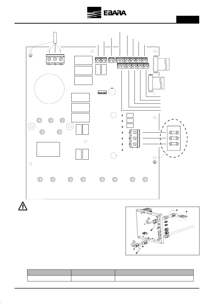
- Each interface cable length for communication and/or pressure transducer should be shorter than 3 meters.
- Use the appropriate cable glands to attach the cable.
- Also ensure that the grid has electrical protection; a high-sensitivity dedicated differential switch (30 mA, class A
for domestic applications, Class B for industrial applications) is particularly recommended.
The type B should be installed for all the residual current-operated protective or monitoring from an
inverter up to the supply voltage.
- In addition to the differential switch, it is advisable to install magneto thermal protection and a voltage disconnect
switch to control the power supply to each Inverter individually.
Ground cable must be connected properly. If the ground cable is not connected, there is an increased risk
of electric shock or fire.
- Use recommended circuit breakers on the supply side as a protection in case of a component failure inside the
inverter. Recommended circuit breaker size are as follows:
b) Installation of pressure units with an inverter:
- The multiple pump units must always consist of pumps that are the same and that, therefore, have the same power
and hydraulic performance. Failure to comply with this point can cause the pump system to malfunction.
- For the Inverter to work, it is essential to use a pressure transducer (4-20 mA).
- The location of the pressure transducer must always be as close as possible to the pump unit, as close as possible to
the pressure tank, and always after the non-return valve of the pump unit. It is essential to install a general cut-off
valve for the pump unit, after the physical location of the pressure transducer.
- If there is more than one pressure transducer in a multiple pump unit (more than one Inverter with a pressure
E-SPD+ MT 2200
E-SPD+ TT 4000
E-SPD+ TT 11000
51
134
64
12
49
-
19
76
38
28
81
40
35
120
61
1∼ 230 Vac
3∼ 400 Vac
3∼ 400 Vac
MT 2200
TT 4000
TT 11000
20 A
16 A
32 A
8
46
-
Section of frequency converter output (mm2)
Maximum distance (meters)
Section of frequency converter input (mm2)
Maximum distance (meters)
2,54
Voltage Supply E-SPD+ Model Circuit breaker size
1,5 41,52,5

8
EN
transducer connected), the network of interconnected Inverters will decide automatically, and with prior reliability
tests of the readings of the existing transducers, which is the transducer that will be used as the general pressure
sensor for the whole group.
- If the designated transducer functions erroneously, (indicated on the display with *) the set of Inverters will decide
to automatically change the principal transducer for another that provides more precise readings. The rest of the
transducers will remain on standby ready to be used when required.
c) Installation on a motor:
- Replace the cover of the motor terminal box with the motor support adapter (parts 5 and 11a) provided.
- Screw the metal radiator to the motor support adapter with the help of the 2 screws provided for this purpose
(parts 9 and 11b).
-Tighten the appropriate cable glands to guarantee the declared protection rating (part 10).
- Carry out the electrical connections between the power circuit and the motor using the electric cables supplied
(item 6).
- Connect the power circuit to the cover + control circuit (part 1) using the flat cable.
- Screw the assembly together (part 13).
d) Installation on a wall bracket:
- Fix the wall bracket to the wall through the 3 rear holes of the wall bracket (part 7).
- Place the fan at the base of the wall bracket, ensuring upwards airflow (part 8).
- Place the inverter assembly inside the wall bracket, ensuring that the 2 ends of the metal radiator are inside the
wall bracket.
- Fix the inverter to the wall bracket using the 2 side screws drilled into the metal radiator (part 14).

EN
9
EN
8 - ELECTRICAL CONNECTIONS
Power connections
*For 230/400 V motors
B
A
B
A
E-SPD+ MT2200
E-SPD+ TT4000
E-SPD+ TT 4000
It is necessary to install a magnetic core (A).
You will find it in the accessories box. It must be fixed to:
MT) and TT) on the main power cable of the inverter, as closeas
possible to the cable gland, TT) On the cable between inverter
and motor, as close as possible to the inverter connector, until
a CLICK (B) is heard.
MT 2200
TT 4000
E-SPD+ MT2200
E-SPD+ TT4000
Single phase 230 V
Three-phase 400 V
Three-phase 230 Vac (DELTA connection*)
Three-phase 400 Vac (STAR connection*)
Model Power supply Motor
INPUT 3
0-10V PTC 4-20mA(2)
INPUT 4 MODBUS
MT 2200 TT 4000
POWER SUPPLY
400VAC 3 ~
POWER SUPPLY
230VAC 1 ~
RELAY 2 OUTPUT
RELAY 1 OUTPUT
FAN
DIGITAL INPUT 2
FRONT PANEL
MOTOR 230/400Vac
MOTOR 230/400Vac
DIGITAL INPUT 1
PRESSURE TRANSDUCER
RS485 COMMUNICATION

10
EN
Power connections
*For 400/690 V motors
It is necessary to install the magnetic cores (A, B and C).
You will find them in the accessory box.
In the power cable of the frequency converter, one will be installed
on the outside, as close as possible to the cable gland (A).
In the cable between the frequency converter and the motor, one
must be installed that groups all the cables (B) and another that
only groups the 3 phases without the ground (C).
E-SPD+ TT11000 Three-phase 400 V Three-phase 400 Vac (DELTA connection*)
Model Power supply Motor
POWER SUPPLY
400Vac 3 ~
FAN
RELAY OUTPUT 2
RELAY OUTPUT 1
FRONT PANEL
FRONT PANEL
0-10V INPUT
PTC / NTC INPUT
PRESSURE TRANSDUCER 2
PRESSURE TRANSDUCER 1
COMMUNICATION RS485
DIGITAL INPUT 1
DIGITAL INPUT 2
DIGITAL INPUT 3
DIGITAL INPUT 4
MODBUS
MOTOR
400/690Vac

EN
11
EN
Relay 1
Relay 2
FAN
PTC (NTC)
4-20mA
MODBUS
RS485
0-10 V
IN1
IN2
IN3
IN4
Outputs that act as programmed in section 5. ADVANCED PARAMETERS
These outputs are potential free and with a maximum load of 5 amps at 230Vac.
In the operating mode with wall support, since we do not have the cooling of the motorfan itself, we will use the ventilation system that is equipped
with said support as standard to carry out this cooling. This output is 24Vdc and is activated whenever the inverter is activating the motor.
In this input we can connect a motor temperature probe, which will allow us to monitor its status. Allows the connection of a PTC or NTC probe.
The type of probe can be selected as programmed in section 5. ADVANCED PARAMETERS.
Connection of the pressure transducer or temperature sensor (always 4-20 mA), maintaining the correct polarity shown in the connections
diagram of the transducer itself.
In case of one sensor only, always connect to 4-20mA(1) input
In case of second sensor, connect it to 4-20mA(2) input
It allows the monitoring of the frequency inverter through the MODBUS communication protocol.
We can adjust the MODBUS communication configuration as programmed insection 6. FINE SETTINGS.
Note: For MODBUS parameter, refer to MODBUS section.
In these terminals, the interconnection of the different drives that we want tocommunicate must be carried out (maximum 8). The connection is
made point-to-point.Terminals 1 must be connected to each other in the same way as terminals 2.
External input that allows modifying the motor turning speed with the help of a potentiometer as specified in section 5. ADVANCED
PARAMETERS.
The input has 3 contacts: +10, AI1, GND.
If you have a potentiometer with its own power at 10V, connect the signal between between AI1 and GND.
If you have a potentiometer that does not have its own power supply, connect the potentiometer input between +10 and GND and the
potentiometer output to AI1.
This function can be enabled by closing one of the digtal input port and set it to “”Slave 0-10V” in 5. ADVANCED PARAMETERS.
The logic control is:
In modes A (Constant Pressure), B (Differential Pressure), D (Constant Temperature) and E (DifferentialTemperature): (Figure 3a on Page no. 383)
- Stop under 1V.
- Maximum speed above 9V.
- Linear acceleration/deceleration between 1V and 9V.
In mode C (Fixed Speed) logic depends on Slave 1V Setpoint and Slave 9 Setpoint value
a) Slave 1V setpoint is less than Slave 9V setpoint: (Figure 3b on
Page no. 383
)
- Stop under 0,5V
- Input signal under 1V and OFF --> Pump OFF
- Input signal under 1V and pump ON --> Slave 1V Setpoint
- Linear acceleration/deceleration between 1V and 9V.
- Input signal above 9V --> Slave 9V Setpoint
b) Slave 1V setpoint is greater than Slave 9V setpoint: (Figure 3c on
Page no. 383
)
- Stop above 9,5V
- Input signal above 9V and Pump OFF --> Pump OFF
- Input signal above 9V and pump ON --> Slave 9V Setpoint
- Linear acceleration/deceleration between 1V and 9V.
- Input signal under 1V --> Slave 1V Setpoint
In these inputs we can connect any potential-free contact that will perform the functions programmed in section 5. ADVANCED PARAMETERS.
NOTE: Do not supply these inputs with voltage!
SIGNAL DESCRIPTION

12
EN
9 - SCREEN FORMAT
10 - MAIN SCREEN
Current data Programmed data
Pump operation
LED
Inverter voltage
LED
Main display
Manual stop button
Right selection button
Lower button
Raise button
Left selection button
Alarm
LED
H z 4 8 . 9 ( 4 8 . 8 )
A m p 0 8 . 3 ( 0 8 . 9 )
B a r 0 5 . 5 ( 0 5 . 5 )
1 4 : 5 7 M e n u
Current rotation frequency Instant consumption
Current time Current pressure
Nominal consumption Stop frequency
Setpoint pressure Access to the menu

EN
13
EN
11 - OPERATION MODE
11a) Constant pressure
1) Single Pump unit
By the direct reading of the pressure transducer, the variable speed drive is responsible for managing the rotation
speed of the electric motor of the pump, guaranteeing the mains pressure remains fixed and unaltered, inside the
pump’s performance range regardless of the instantaneous demand for flow required. When the demand for flow is
at its greatest, the pressure of the water network decreases. In this point the pressure transducer, which continuously
informs the inverter of the current pressure, causes the inverter to make the electric motor rotate more quickly,
guaranteeing the established working pressure. In contrast, when the demand for flow decreases, the inverter
makes the electric motor rotate more slowly so the pressure of the water network remains unaffected.
For typical hydraulic installation scheme (figure 1) on page no 382.
2) Unit with several pumps (Multi Inverter)
When there is a network of two or more inverters connected together, the system decides in an alternate and
orderly manner which pump must start up first, when there is demand for flow. Once this pump starts to rotate, if
it stops because there is no more demand for flow, the system will start up a different pump the next time it starts
up, rotating all the pumps that comprise the network of inverters so that all the pumps in the inverter network are
started up the same number of times.
If a pump is running and reaches maximum rotational speed and the network pressure does not reach the
established working pressure, the system will decide whether to start up one more pump, to support the first one or
however many are running at that time. At that time the network of inverters will calculate the rotational speed of
the motors that guarantee the minimum electricity demand at the same time as maintaining the working pressure.
Similarly, and with this same premise of maximum energy savings, the system will continually calculate when it can
disconnect each pump that is running at any time.
11b) Differential pressure
In this mode, inverter maintains a differential pressure between the discharge side and suction side of the pump in
circulation system irrespective of the system flow.
The inverter continuously senses the discharge side and suction side pressure. When the demand for flow is at
greatest, the differential pressure decreases. In this point, inverter causes the electric motor to rotate more quickly,
guaranteeing the set differential pressure. In contrast, when the demand for flow decreases, the inverter makes the
electric motor rotate more slowly so the differential pressure of the water network remains unaffected.
This control mode requires either a differential pressure sensor or 2 pressure transducers of same pressure ratings.
Note: In case of a differential pressure sensor, it is necessary to connect the sensor to analog input 4-20mA (1).
In case of two pressure transducers, it is necessary to connect the discharge side sensor to analog input 4-20mA (1)
and suction side sensor to analog input 4-20mA (2).
For typical hydraulic installation scheme (figure 2) on page no 382.
11c) Fixed speed
In this mode, the inverter maintains a fixed motor speed set by the operator.
The speed of the motor then can be changed manually.

14
EN
11d) Constant temperature
In this mode, inverter ensures a constant temperature in the system. For this operation mode, a temperature sensor
should be placed at the location where temperature is to be controlled.
Note: For heating system, set 6. FINE TUNING parameter 6.03 to Positive and for cooling system, set 6. FINE
TUNING parameter 6.03 to Negative.
Caution: Use correct type of temperature sensor depending on the application.
11e) Differential temperature
In this mode, inverter ensures a constant differential temperature in the system. This operation mode requires
either a differential temperature sensor or two temperature sensors of same temperature ratings.
Caution: Use correct type of temperature sensor depending on the application.
Note: For temperature control mode, proportional and integral control setting may have to be adjusted according
to the distance between the temperature sensor and the heat exchanger.
12 - START-UP WIZARD
The first time you connect the voltage to your unit, a start-up wizard will run in which you can configure the basic
parameters to be able to start up the pump unit. For operation modes with more than 1 pump, this wizard only runs
on one of the units regardless of the total that are connected.
While using this wizard the red LED will blink indicating that this process is under way.
You must choose between the different operating modes of the
system, which are:
MODE A: CONSTANT PRESSURE
MODE B: DIFFERENTIAL PRESSURE
MODE C: FIXED SPEED
MODE D: CONSTANT TEMPERATURE
MODE E: DIFFERENTIAL TEMPERATURE
E s p a n o l
E n g l i s h
F r a n c a i s
O K
F2
F2
A
CE
o
3
a
F
r
F
S
:
OO
R
C
P
l
1
l
0
EN
N
O
R
ei
E
T
R
Ap
M1
LFSA
F
N
E
s
R
E
A
T
t
OI
T
S
A
S
A
D
c
A
O
A
K
D
N
U
Se

EN
15
EN
The system automatically indicates the number of Inverters (x)
interconnected to your network. It is an indicative parameter and
cannot be modified.
With F1 button you can repeat the automatic search if the value shown
“x” is different from the real value.
If you perform various searches and the value still does not coincide,
there is probably a connection error in the network of inverters.
Before carrying out this point, you must use the graphic sign on the
pump motor to check its rotation direction, as it may be clockwise or
anti-clockwise depending on the pump model.
In this point you can see how the motor makes a sequence of slow
turns so you can easily see whether the rotation direction is correct. It
performs 6 rotation tests and stops the motor.
F1 button restarts the rotation test.
If the rotation direction is not correct, select NO with the arrows and
restart the test by pressing F1 to verify that the rotation direction has
been changed successfully.
Once you have verified that the rotation direction is correct, select YES
and then accept it with F2 button.
Use the arrow keys to increase or decrease the value that is blinking
and use F2 button to change to the next value. The sequence of values
is:
DAY →MONTH →YEAR →HOUR →MINUTES
The lower left part of the display indicates the day of the week
calculated automatically according to the date entered.
When you modify the last value (minutes) you can accept the changes
by pressing F2 button.
Note: At any point of the date you can go back to the previous value
by pressing F1 button.
F2F1
CM
PW
O
3
N
F
OP
RI
.
l
1
ES
Z
e
R
Ap
S
LF
R
O
A
1
s
T
P
A
T
t
TD
A
X
A
-
U
c
A
O
A
K
A
F
O
Se
U
aRretp
F2
R3
CE
R
T
O
t
3
e
O
B
a
F
R
T.
OO
D
A
U
l
1
p
-S
EN
N
T
T
e
A
e
W
E
S
A
T
t
UT
RFOA
F
I
1
s
I
S
T
A
T
a
PA I
N
O
A
X
A
Z
T
A
c
A
r
A
t
A
T
O
S
R
S
A
F2F1
A3
CE
E
T
O3
O
BF
T.
OO
C
A
U
l
1
IR
EN
T
T
T
e
A
C
E
S
A
T
t
OO
RFYS
F
I
1
s
O
S
T
A
T
a
NT I
E
O
A
N
A
R
T
A
c
A
O
A
K
A
T
O
S
R
S
R
teaRpe
F2
C3
CE
E
T
0
3
A
/
F
O.
OO
C
E
1
d
2
N
R
EN
T
T
/
a
6
U
I
S
A
0
N
F
O
DFNT
F
A
2
y
R
M
1
A
9
e
I
TI
D
N
A
2
A
E
E
1
c
A
x
A
t
G
T
-
S
:
S
R
seeWdn
F2
C3
CE
E
T
0
3
A
/
F
O.
OO
C
E
1
d
2
N
R
EN
T
T
/
a
6
U
I
S
A
0
N
FO
DFNT
F
A
2
y
R
M
1
A
9
e
ITI
D
N
A
2
A
E
E
1
c
A
O
A
k
G
T
-
S
:
S
R
seeWdn

16
EN
In this point you must enter the nominal consumption of the motor,
increase or decrease the value using the arrow keys and validating
with F2 button.
Note: The nominal consumption is indicated on the name plate of the
motor. You must choose the correct value, for example if you connect
an inverter MT select the value 230 V and for the inverter TT, select
400 V.
Use the arrow keys to enter the maximum pressure scale of the
connected pressure transducer.
This value is indicated on the data plate of the pressure transducer,
and must always be between 4 and 20 mA.
Validate this with F2 button.
Use the arrow keys to enter the pressure at which you want the unit
to work.
You must take great care that this value is always within the working
curve of the pump, and always try to avoid the extremes of the curve,
in other words with flows near 0 or very low pressures.
Validate this with F2 button.
Once you have reached this point, the frequency converter will
program itself to know when it no longer has any demand for flow
and should stop. To do this it will ask for help to understand the
features of the installation to which it is connected.
If at this time it is detected that the pressure of the installation is equal
to or greater than the working pressure, the user will be informed that
it is necessary to open the water supply of the equipment in order to
reduce the pressure below the working pressure.
12a) Mode A: CONSTANT PRESSURE
F2
F2
F2
F2
3
P
3
33
C
C
R
R
R
K
K
O
O
o
9
3
3
a
a
R
R
B
B
r
.
F
F
S
S
F
E
S
O
O
E
E
C
P
T
l
B
1
1
l
l
R
N
T
W
W
N
N
H
R
O
e
a
A
A
i
4
W
I
K
R
A
A
T
T
p
p
EO
O
O
F
F
SR
R
F
F
E
.
.
s
r
S
V
S
S
T
A
A
T
T
t
t
Q
D
P
O
I
S
T
A
A
S
A
A
E
E
U
U
A
A
c
c
A
A
O
A
A
K
.
R
O
A
S
S
R
R
e
e
A
R
3
CR
R
K
O
o
3
a
R
B
r
F
S
T.
OE
D
I
1
l
1
l
-S
WN
N
N
4
e
A
i
W
S
a
A
T
p
UT
OFC R
F
G
.
s
I
S
r
A
T
t
PA I
P
O
A
0
A
Z
U
A
c
A
O
A
K
A
E
B
S
R
e
A
R
3
CL
R
N
O
o
3
a
A
B
r
F
S
T.
OE
D
S
1
l
1
l
-S
TN
N
D
0
e
A
i
W
S
a
A
T
p
UT
RFCR
F
U
.
s
I
C
r
A
T
t
PA I
E
O
A
0
A
Z
A
A
c
A
O
A
K
A
R
B
S
R
e
A
R
3
CE
R
T
O
o
3
a
O
B
r
F
S
T.
OO
D
O
U
l
1
l
-S
EN
N
R
5
e
A
i
W
E
m
A
T
p
UT
MFCR
F
A
.
s
I
N
p
A
T
t
PA I
U
O
A
0
A
Z
T
A
c
A
O
A
K
A
R
A
S
R
e
A

EN
17
EN
Once the drive detects that the water pressure in the installation
is lower than the working pressure, the installer will be asked
to completely close the water outlet from the equipment to the
installation.
For a few seconds and depending on the capacity of the installation,
the equipment will reach the working pressure in order to
automatically calculate which the stop frequency of the equipment is.
Once the stop frequency has been calculated, the configuration
wizard will show the calculated stop frequency and request validation
of the calculated frequency from the installer.
It shows a text for a few seconds indicating that the wizard has
finished successfully before showing the main screen.
F2
F2
O
E
3
C
C
E
E
R
C
A
W
O
U
0
3
3
F
F
B
S
.
F
F
F
P
S
.
O
O
O
O
C
Y
S
I
4
F
U
C
B
1
1
R
A
W
T
0
E
E
N
N
H
N
Z
0
I
T
C
a
A
4
Q
R
S
D
S
L
4
T
H
E
F
I
O
S
T
L
L
F
F
R
2
I
O
z
H
F
A
.
N
1
1
E
r
S
U
D
R
R
T
L
0
T
T
z
Q
R
Z
P
T
H
I
D
H
S
O
F
T
S
E
E
D
D
A
Y
.
A
A
A
A
.
E
A
I
E
O
O
U
R
2
A
N
H
Note: All the data entered or calculated in the wizard can be modified later through the unit menu.
START-UP WIZARD IN SYSTEMS WITH TWO OR MORE PUMPS
In systems with two or more pumps, the start-up wizard will run in all the units at same time.
Once the wizard has finished in one of these units, the other units on the network will be fully programmed with the
same data. It will only remain to run the rotation test of its wizard in all the other pumps.
Once their rotation tests have been performed, the inverters will be fully programmed.
O33
CR
K
O3
a
R
BF
S
S
OE
P1
l
E
WN
RA
I
O
A
T
p
C
OFNR
F
A
E
V
S
K
A
T
t
DL
D
S
A
S
A
E
U
A
c
A
O
A
K
R
S
R
e
le A tsAaAAc
OKSS
teaRpe
F1

18
EN
We select the minimum scale range of the differential pressure
transducer, that is, the reading in bar that we will have when the
transducer gives the inverter a reading of 4mA.
By pressing the F2 button we select the value.
We select the maximum scale range of the differential pressure
transducer, that is, the reading in bar that we will have when the
transducer gives the inverter a reading of 20mA.
By pressing the F2 button we select the value.
Use the arrow keys to enter the maximum pressure scale of the
connected pressure transducer. This value is indicated on the data
plate of the pressure transducer, and must always be between 4 and
20 mA.
Validate this with F2 button.
F2
F2
F2
EE33
CC
L
OO
DP
SR
oo
33
aa
ET
rr
FF
SS
RRNN
OOOO
RR
IR
SA
ll
P
ll
AA
UU
EENN
SS
FE
UN
ee
R
ii
SS
T
ET
AA
R
pp
OOMM
12
FFESER
::
FS
RS
ss
EE
I
NE
AA
TT
tt
FFBBII
RU
I
AA
EM
AA
NN
A
SR
cc
AA
OO
AA
KK
NE
ST
SS
OS
ee
SS
12b) Mode B: DIFFERENTIAL PRESSURE
In this point, the user can select whether they have 1 differential pressure sensor or 2 independent pressure sensors.
The selection of one option or another varies the start-up wizard. Use the arrow keys to select Option A or Option
B. By pressing the F2 button we select the option.
OPTION A: 1 DIFFERENTIAL PRESSURE SENSOR
OPTION B: 2 PRESSURE TRANSMITTERS
F2
F2
R
R
3
3
Cm
m
R
R
S
S
O
O
o
o
3
3
a
a
S
S
B
B
r
r
F
F
S
S
T
T
.
.
P
P
A
A
D
D
.
.
1
1
l
l
1
1
l
l
-
-
S
S
R
R
-
-
N
N
1
e
e
A
A
i
i
W
W
B
B
A
A
T
T
p
p
U
U
T
T
E
E
F
F
A
A
U
U
F
F
V
V
0
0
s
s
I
I
-
-
a
a
A
A
T
T
t
t
P
P
A
A
I
I
L
L
0
0
A
A
.
.
A
A
Z
Z
4
02
r
r
c
c
A
A
O
O
A
A
K
K
A
A
E
E
S
S
R
R
e
e
A
A
R
3
CL
R
N
O
o
3
a
A
B
r
F
S
T.
E
D
S
1
l
1
l
-S
T
N
D
1
e
A
i
W
S
B
A
T
p
UT
RFCR
F
U
0
s
I
C
a
A
T
t
PA I
E
0
A
.
A
Z
A
r
c
A
O
A
K
A
S
R
e
A
OPTION A OPTION B

EN
19
EN
Use the arrow keys to enter the pressure at which you want the unit
to work.
You must take great care that this value is always within the working
curve of the pump, and always try to avoid the extremes of the curve,
in other words with flows near 0 or very low pressures.
Validate this with F2 button.
Using the buttons we can select the minimum operating frequency
for the pump.
Validate this with F2 button.
It shows a text for a few seconds indicating that the wizard has
finished successfully before showing the main screen.
By pressing the arrow buttons we set the continuous operating
frequency of the pump.
Validate this with F2 button.
12c) Mode C: FIXED SPEED
In this mode, the inverter maintains a fixed motor speed set by the operator.
The speed of the motor then can be changed manually.
COMMON FOR BOTH OPTIONS A (1 DIFFERENTIAL PRESSURE SENSOR)
AND B (2 PRESSURE TRANSMITTERS)
F2
R3
CR
R
K
O
o
3
a
R
B
r
F
S
T.
E
D
I
1
l
1
l
-S
W
N
N
e
A
i
W
S
B
A
T
p
UT
OFR
F
G
2
s
I
S
a
A
T
t
PA I
P
5
A
.
A
Z
U
r
c
A
O
A
K
A
E
S
R
e
A
F2
R3
CY
R
U
O
o
3
a
I
B
r
F
S
T.
M
D
MM
1
l
1
l
-S
I
N
2
e
A
i
W
E
H
A
T
p
UT
NRQ
F
F
5
s
I
N
z
A
T
t
PA I
E
0
A
.
A
Z
C
c
A
O
A
K
A
U
S
R
e
A
EA
US
S
F
C
W
I
C
R
D
L
IT
IH
N
E
D
L
ZH
S
FSY
A
E
U
H
F2
R3
CY
R
N
O
o
3
a
K
B
r
F
S
T.
W
D
GI
1
l
1
l
-S
O
N
2
e
A
i
W
E
H
A
T
p
UT
RRQ
F
F
5
s
I
N
z
A
T
t
PA I
E
0
A
.
A
Z
C
c
A
O
A
K
A
U
S
R
e
A

20
EN
It shows a text for a few seconds indicating that the wizard has
finished successfully before showing the main screen.
We can select how we want the frequency inverter to behave based on
the detected temperature, that is, if the temperature increases and we
set the PI direction to positive, the motor will decelerate.
On the other hand, if the temperature increases and we set the value
to negative, the motor will accelerate.
By pressing the F2 button we valid it.
We select the temperature that we want to detect when the
temperature sensor reaches its minimum value (4mA).
By pressing the F2 button we set the value.
We select the temperature that we want to detect when the
temperature sensor reaches its maximum value (20mA).
By pressing the F2 button we set the value.
12d) Mode D: CONSTANT TEMPERATURE
In this mode, inverter ensures a constant temperature in the system. For this operation mode, a temperature sensor
should be placed at the location where temperature is to be controlled.
Note: For heating system, set 6. FINE TUNING parameter 6.03 to Positive and for cooling system, set 6. FINE
TUNING parameter 6.03 to Negative.
Caution: Use correct type of temperature sensor depending on the application.
EA
US
S
F
C
W
I
C
R
D
L
IT
IH
N
E
D
L
ZH
S
FSY
A
E
U
H
F2
R3
C
R
O
o
3
a
P
B
r
F
S
T.D
DI
P
l
1
l
-S N
I
o
e
A
i
W
O
v
A
T
p
UT
ET
F
R
s
s
I
N
e
A
T
t
PA I
C
t
A
i
A
Z
c
A
O
A
K
A
I
i
S
R
e
A
F2
F2
R
R
3
3
C
C
)
)
R
R
O
O
o
o
3
3
a
a
P
P
B
B
r
r
F
F
S
S
T
T
.
.
T
T
D
D
V
V
.
.
1
l
l
1
1
l
l
-
-
S
S
E
E
N
N
A
A
0
e
e
A
A
i
i
W
W
4
02
º
º
A
A
T
T
p
p
U
U
T
T
M
M
U
U
F
F
L
L
0
0
s
s
I
I
m
m
C
C
A
A
T
T
t
t
P
P
A
A
I
I
E
E
0
0
A
A
.
.
A
A
Z
Z
A
A
c
c
A
A
O
O
A
A
K
K
A
A
(
(
S
S
R
R
e
e
A
A
This manual suits for next models
2
Table of contents
Languages:
Other EBARA Inverter manuals
Popular Inverter manuals by other brands

Carel
Carel Power + PSD2 Series Technical leaflet

Mitsubishi Electric
Mitsubishi Electric 800 Series instruction manual

Solutronic Energy
Solutronic Energy GridManager user manual

Onan
Onan DYC Series Operator's manual and parts catalog

Schaefer
Schaefer IT 1686.4 General instructions

TECO
TECO N3 Series operating manual