INSTALLATION AND OPERATION MANUAL SOLAR MODULES Q.TRON (BLK) M-G2.X INSTALLATION AND OPERATION MANUAL SOLAR MODULES Q.TRON (BLK) M-G2.X6 7
2 Planning
2.2 Requirements
Installation Site
Please note the following guidelines that apply to the installation
site:
■Solar modules are not explosion-proof and are not suitable for
use in explosive environments.
Do not operate solar modules near highly flammable gas and
vapors (e.g. gas tanks, gas stations).
Do not install modules in enclosed space.
Do not install modules in locations where they may be
submerged in water (e.g. floodplains).
Do not use modules as a substitute for the normal roofing (e.g.
modules are not watertight).
Do not install modules in close proximity to air conditioning
systems.
Do not install modules above 13,120 ft (4,000 m) altitude above
sea level.
Contact with saline water (e.g. spray water from the sea) and
salt aggregation on the modules must be avoided.
Do not bring any chemical substance (e.g. oil, solvent etc.) into
contact with any part of the panel. Only substances, which are
released by Qcells, are allowed to be used during installation,
operation and maintenance.
Any installation of modules on surfaces of water is prohibited.
This includes installations on floating as well as pile-based
platforms. Qcells may extend the coverage of its warranty to
such installations, based on a case by case assessment of
the system design and location. A prior written consent by the
warrantor is required in any case.
Prevention of Shadowing Effects
Optimal solar irradiation leads to maximum energy output:
For this reason, install the modules so that they face the sun.
Avoid shadowing (due to objects such as buildings, chimneys
or trees).
Avoid partial shading (for example through overhead lines, dirt,
snow).
Limitations
The solar modules are designed for the following applications:
■Operating temperatures from –40 °F to +185 °F.
■Pull loads and push loads according to chapter 2.3 (‘Test
Load’ in accordance with IEC 61215 and ‘Design Load ×1.5’ in
accordance with UL 61730).
■Installation using a mounting structure for solar modules.
Mounting Structure Requirements
Requirements for the mounting structure:
■Conform to the necessary structural requirements.
■Compliant with local snow and wind loads.
■Properly fastened to the ground, the roof, or the façade.
■Forces acting on the module are relayed to the mounting
substructure.
■Ensures sucient rear ventilation of the module.
■Avoid the usage of different metals to prevent contact
corrosion.
■Allows for stress-free expansion and contraction due to
temperature fluctuations.
Ensure that no additional forces are applied through the
mounting system into the module except for the wind and
snow loads. Additional forces and moments of torque at the
mounting positions caused by torsions, displacements or
vibrations in the mounting system are not allowed.
Ensure that the clamps and the mounting frame are compatible.
Clamp System Recommendations
Use customary clamps that satisfy the following requirements:
■Clamp width: ≥ 1.57 in (40 mm).
■Clamp height compliant with a 1.18 in (30 mm) frame height.
■Clamp depth: 0.28-0.47 in (7-12 mm). (applicable for all CL
clamping mounting options at section "2.3 Mounting options")
■Clamps are not in contact with the front glass.
■Clamps do not deform the frame.
■Clamps that satisfy the structural requirements based on the
conditions of the installation site according to the applicable
regulations and technical standards.
■Long-term stable clamps that securely ax the module to the
mounting frame.
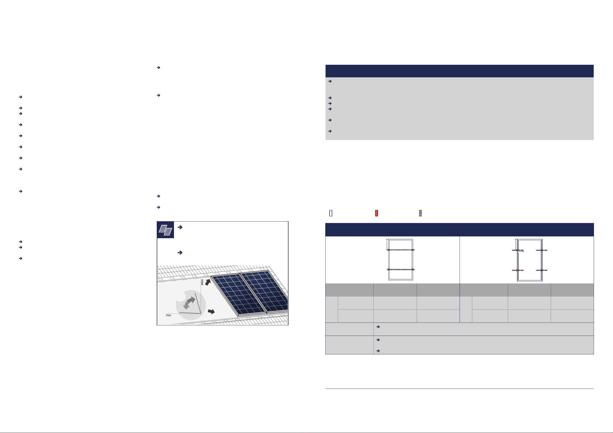
Module Orientation Requirements
■Vertical or horizontal installation is permitted.
Ensure that rain and melting snow can run o freely. No water
accumulation.
Ensure that the drainage holes in the frame are not covered.
No sealing.
75°
3°
Maintain the permissible angle of inclination.
■Minimum angle of inclination: 3°
■Inclination angles above 75° may be limited by
local regulations
Standing water on the modules glass needs to be
avoided.
2 Planning
2.3 Mounting options
REQUIREMENTS OF ALL MOUNTING OPTIONS
The loads in the table are related to the mechanical stability of the solar modules. The mechanical stability of the mounting system
including clamps has to be evaluated by the system supplier. The listed test load values have been determined with the following
clamp parameters: clamp width = 1.57 in (40 mm) and clamp depth = 0.39 in (10 mm).
The system installer is responsible for the determination of location-specific load requirements.
Ensure, that the connection cables of the junction box do not run between laminate and mounting rails.
Modules bend under load. Therefore, sharp objects (e.g. screws, ballast stones, rail ends, rails with burrs or sharp corners) must
not be placed near the module backside so as not to touch the laminate under load.
Ensure that the junction boxes do not touch the mounting structure (e.g. shorts rails, ballast, etc.) or the rooftop under load.
Clamps or insertion profiles etc. must not touch the glass (even under load).
Unbalanced loads (e.g. snow overhangs, snowdrifts) which result in locally significantly increased loads must be removed or
avoided by technical measures.
Loads according to IEC 61215-2:2016 and UL 61730-2:2017 except for design loads lower than 1600 Pa which
do not fulfill the requirements of the standards. The test procedure is always according to IEC 61215-2:2016.
Design loads result from the safety factor 1.5.
Mounting options with clamps
The illustrated installation options apply for both horizontal and vertical module orientation.
Module Clamp Mounting rail
4 CLAMPS ON LONG SIDE &
2 CONTINUOUS RAILS PARALLEL TO SHORT SIDE 4 CLAMPS ON LONG SIDE(SHORT RAIL ALLOWED)
CL1a
LL
CL1b
L
0.59 - 8.27
(15 - 210)
POSITION OF
CLAMPS* [in]
TEST LOAD
PUSH / PULL [Pa]
DESIGN LOAD
PUSH / PULL [Pa]
POSITION OF
CLAMPS* [in]
TEST LOAD
PUSH / PULL [Pa]
DESIGN LOAD
PUSH / PULL [Pa]
L
0.79 - 11.8
(20 - 300 mm) 2400 / 2400 1600 / 1600
L
7.87 - 11.8
(200 - 300 mm) 2600 / 3600 1730 / 2400
5.91 - 11.8
(150 - 300 mm) 5400 / 3600 3600 / 2400 0.79 - 11.8
(20 - 300 mm) 1600 / 2400 1060 / 1600
CL1a Ensure that module frame is fixed directly on the rail of the substructure (no spacer allowed between the
module and substructure).
CL1b
Short mounting rails are permissible, if they overlap with the module less than 8.27 in (210 mm). Maintain a
minimum distance (clearance) of ≥ 1.38 in (35 mm) between frame bottom edge and roof top or ballast.
Minimum support depth of 0.59 in (15 mm) is required on the back side of the module.
*Distance between outer edge of module and middle of the clamp.