Smart power ER-6.2 User manual

9991031 Rev. M
A.C. MODULAR
GENERATOR SYSTEM
OWNERS MANUAL
MODEL#: ER-6.2, ER-8, ER-10 and ER-110
For Compartment or Top Mounting

Smart Power Systems®
A. C. MODULAR GENERATOR SYSTEM Page 1 of 52
Table of Contents
Section Page
Disclaimer..........................................................................................................................5
Description of Product......................................................................................................6
System Specifications......................................................................................................9
Pre-Installation Guide.....................................................................................................11
Installation Guide............................................................................................................16
Hose Installation Guidelines .......................................................................................... 20
Operation......................................................................................................................... 28
Special Operating Instructions ......................................................................................35
Maintenance Instructions............................................................................................... 36
Troubleshooting Guide...................................................................................................39
Pump Adjustment............................................................................................................ 48
SPS Model Matrix............................................................................................................52
Doc. 9991031 Rev. M
ECO #16417

Smart Power Systems®
A. C. MODULAR GENERATOR SYSTEM Page 2 of 52
WARNING:
Do not install or operate the A.C. modular generator system without reading this entire
manual.
The A.C. modular generator system will generate enough voltage to produce a fatal
electrical shock. Do not perform any wiring installations or modifications while the system
is operating. Never touch any live connections while the system is operating. Never
operate the system with the generator wiring enclosure open. Install and secure cover
before operating.
The installation of the Smart Power Systems®A.C. modular generator system is to be
done in accordance with applicable sections in the National Fire Protection Association’s
document NFPA 1901, National Electrical Code®, and/or other applicable, recognized
electrical codes and by a certified electrician.
Never directly expose the generator to any liquids, especially water, oil, or solvents.
Electrical shock, fire and/or damage to the generator can occur and will void the system’s
warranty.
Smart Power Systems® hydraulic generators, as well as all generators, must be sufficiently
protected from the environment to prevent damage to the stator. Smart Power stators go
through a very important double-dip coating process prior to generator assembly,
however, exposure to direct water sprays can cause the stator to electrically short.
Generator damage and electrical shock can occur.
Caution should be taken during truck pressure washing, since water damage to the
generator can occur if directly sprayed with high water pressure. Though Smart Power
Systems® (SPS) generators are enclosed as much as possible, direct spray through the
cooler, fan or open lid can still cause such damage.
Excessive road spray/salt can also cause an electrical short of the stator in the generator
and can also shorten the generator’s operating life. To prevent this type of damage, do not
mount the system where it will be exposed to road spray.
Evidence of water damage, road spray/salt infiltration, and improper mounting will void the
generator warranty.
Avoid physical contact with any of the components of the A.C. modular generator system
during its operation or immediately after its use. The components of this system will get
hot enough to cause burns and could ignite combustible materials.
Do not mount or locate anything inside of the framework. System overheating could result
and void the system’s warranty.

Smart Power Systems®
A. C. MODULAR GENERATOR SYSTEM Page 3 of 52
Never operate the system with leaks of any type. Clean up any hydraulic fluid that is
spilled or has leaked out of the system. Hydraulic fluid is combustible, and ignition may
occur.
With the exception of oil filter periodic replacement, never modify or remove any of the
components within the tray assembly.
Never modify or remove any of the components within the pump or the controls mounted
to the pump. This includes all fittings and tubing that are originally provided with the A.C.
modular generator system.
Never make any adjustments to the pump other than for flow control. If it appears the
pump needs to be adjusted, contact Smart Power Systems®at (231) 832-5525 before
proceeding. Damage to the generator from improper pump adjustment will void the
system’s warranty.
Never attempt any adjustments or repairs to the A.C. modular generator system (other
than pump flow control) while the vehicle engine is running and the PTO is engaged.
Never operate the system with the hydraulic fluid exceeding 195
F. Above this
temperature, hydraulic fluid can rapidly oxidize and deteriorate causing generator
performance problems. Operating the system while the hydraulic fluid is above 195
F will
void the system’s warranty.
Hydraulic fluid is combustible and toxic. In the event of human contact with hydraulic fluid,
generously flush body part (eyes, skin, etc.) with running water. Avoid inhalation of any oil
mist or vapor. Do not ingest hydraulic fluid. In case of fire, use foam, dry chemical or
carbon dioxide to extinguish flame.
Do not exceed the wattage rating of the generator. The generator may be permanently
damaged and the generator and hydraulic components may reach temperatures that could
cause severe burns upon human contact with the components. Operating the generator
system at wattages above the system’s rating will void the system’s warranty.
Disengage the system immediately if a hydraulic fluid leak is detected. Operation of the
A.C. modular generator system with low fluid level will result in permanent damage to the
hydraulic components in the system and will void the system’s warranty.
Do not attempt to operate the generator with the tray assembly top lid open. Do not
tamper with the top lid interlock switch or the hydraulic fluid level sensor.
Never attempt to operate the system without hydraulic fluid. Always maintain a fluid level
between ½ to ¾ full in the sight gage.
Operating the A.C. modular generator system in the presence of flammable vapors may
result in an explosion.

Smart Power Systems®
A. C. MODULAR GENERATOR SYSTEM Page 4 of 52
Use only hoses that meet or exceed the minimum requirements specified in this manual.
A ruptured hose can cause personal injury and/or damage to the generator system.
Do not operate the system under electrical load with air in the hydraulic fluid (the system
will make a growling sound). Do not allow anything to contact the hydraulic hoses that will
cause a kink, pinch or chaffing. The A.C. modular hydraulic system generates hydraulic
pressures approaching 3600 psi. A ruptured hose may result from abrasion, discharging
hot, high-pressure hydraulic fluid, which can cause serious personal injury, fire, and/or
damage to the system.
Never remove the guards on the generator to expose the rotating fan or motor coupling.
Personal injury will result if fingers, hair or loose clothing come in contact with rotating
components.

Smart Power Systems®
A. C. MODULAR GENERATOR SYSTEM Page 5 of 52
Disclaimer
Although SPS has taken all reasonable care to ensure that the information contained in
this installation manual (including without limitation, references, databases, resources,
specifications, illustrations and instructions) was accurate in all material respects at the
time of publication, SPS PROVIDES NO ASSURANCE, REPRESENTATION,
WARRANTY OR GUARANTEE, expressed or implied (including third party liability), with
regard to this manual, including without limiting the generality of the foregoing, with regard
to its accuracy, reliability or completeness. The entire information contained in this
installation manual is provided by SPS “AS IS” and without warranty of any kind, express
or implied, including (but not limited to) any implied warranties or merchantability, fitness
for any particular purpose, or non-infringement. Accordingly, by using the SPS unit and
this information, you agree that, to the greatest extent permitted by law, SPS (including,
without limitation, its subsidiaries, affiliates, agents, officers, directors, employees and
insurers) is not and will not be liable for losses or damages resulting from this installation
manual, its use, any information contained therein or the installation of the SPS unit.
This installation manual contains references to certain database and resources. As SPS
has no control over these database and resources, you acknowledge and agree that SPS
is not responsible or liable for any content, advertising, products, information or other
materials on or available from such database or resources. You further acknowledge and
agree that SPS shall not be responsible or liable, directly or indirectly, for any damage or
loss caused or alleged to be caused by or in connection with use of or reliance on any
such content, information goods or services available on or through any such database or
resources. All product illustrations and specifications are based upon current information
at the time of publication. Although descriptions are believed correct, complete accuracy
cannot be guaranteed. SPS reserves the right to make changes of any kind at any time,
without notice or obligation, in the information contained on this installation manual. All
data and information of any kind are subject to change without notice and SPS assumes
no obligation to update or correct information in this manual.
As some states do not allow the exclusion or limitation of liability for consequential or
incidental damages, the limitation contained herein may not apply to you. In such states,
SPS’ liability is limited to the greatest extent liability limitation is permitted by applicable
law.

Smart Power Systems®
A. C. MODULAR GENERATOR SYSTEM Page 6 of 52
Description of Product
Hydraulic Generator Applications:
This heavy-duty electronically controlled generator system has been designed to meet the
most demanding mobile applications. It provides 120/240 volt AC @ 60 Hz from no-load to
full load, handling electrical loads of 6200, 8000 and 10000 watts, depending on model.
How our System works:
A generator driven by a hydraulic motor delivers the electrical power. The motor turns at
3600 RPM as controlled by the flow of hydraulic fluid through an electrically controlled
proportional valve. The proportional valve is directly driven by the system controller. The
piston pump delivers fluid to the proportional valve through installer-supplied PTO
mounted to the vehicle’s transmission.
Heat generated in the hydraulic fluid as it passes through the various components in the
system is cooled by a heat exchanger and fan. A filter removes impurities in the fluid. A
venturi boost assembly monitors the volume of oil in the hydraulic circuit and feeds the
system from the reservoir as needed.
Essentially, the only system maintenance required is periodic replacement of the hydraulic
fluid filter and adding hydraulic fluid to maintain the fluid level (when the hydraulic fluid is
between 70and 80F, it should be at the ¾ mark on the sight gauge).
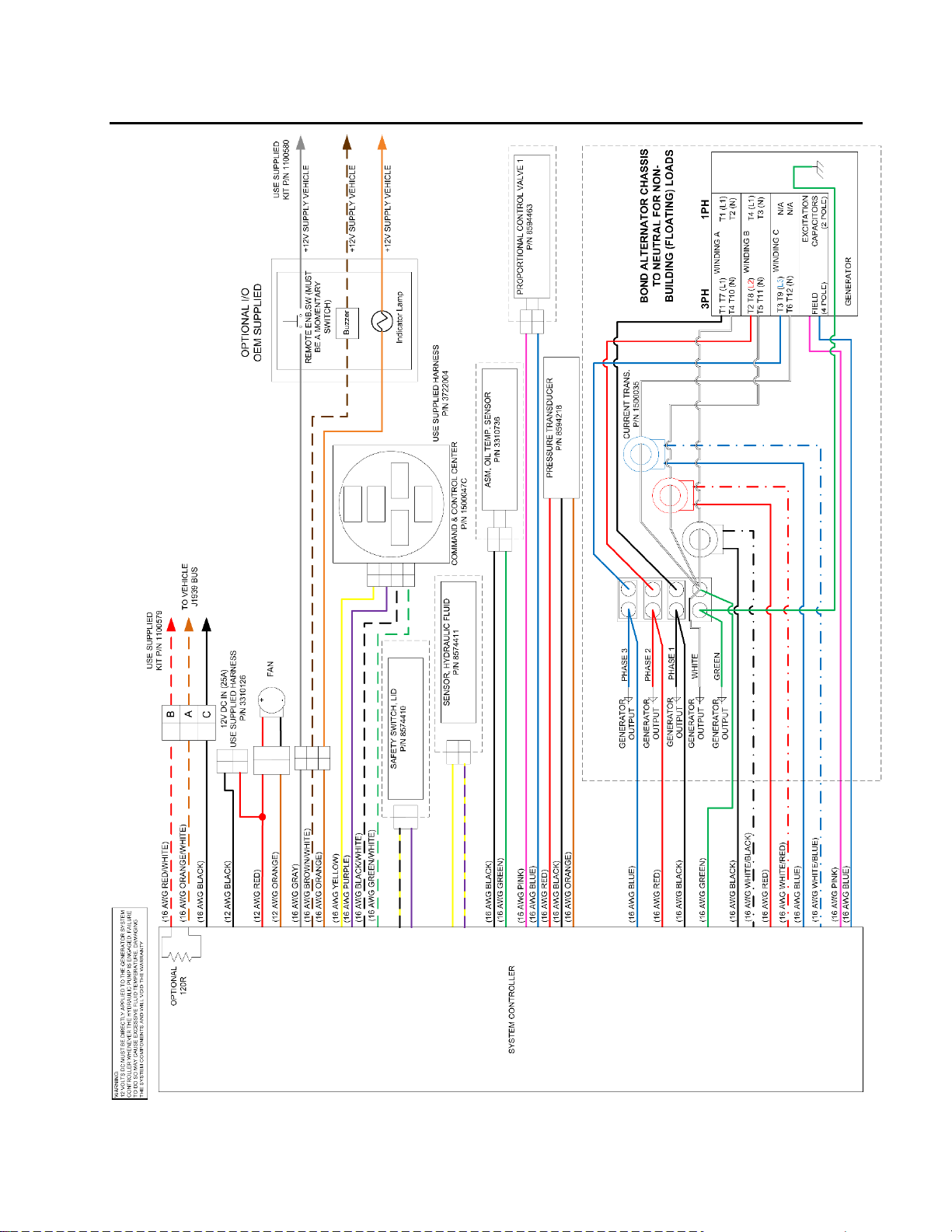
Generator hydraulic and electrical schematics: Reference Figures 1 and 2.

Smart Power Systems®
A. C. MODULAR GENERATOR SYSTEM Page 7 of 52
CASE DRAIN
xy
RESERVOIR
PUMP
PROPORTIONAL
VALVE
CASE DRAIN
MOTOR
COOLER
FILTER
BOOST BLOCK
VENTURI BOOST
CHECK
VALVE
IN
BP
REG
Figure 1 –Hydraulic Generator Schematic for ER-6.2, ER-8, ER-10 and ER-110
Smart Power Systems®
A. C. MODULAR GENERATOR SYSTEM Page 8 of 52
Figure 2 –Generator Electrical Schematic for ER-6.2, ER-8, ER-10 and ER-110

Smart Power Systems®
A. C. MODULAR GENERATOR SYSTEM Page 9 of 52
System Specifications
MODEL OF
GENERATOR
ER-6.2
ER-8
ER-10
ER-110
Generator
Type
Speed
Frequency
Voltage
Amperage
Output
Power
AC Inductive
3600 RPM
60 Hz
240 VAC or
120/240 VAC
52A @ 120 VAC or
26A @ 240 VAC
6.2 KW continuous
7.5 KW peak
AC Inductive
3600 RPM
60 Hz
240 VAC or
120/240 VAC
67A @ 120 VAC or
34A @ 240 VAC
8 KW continuous
9 KW peak
AC Inductive
3600 RPM
60 Hz
240 VAC or
120/240 VAC
84A @ 120 VAC or
42A @ 240 VAC
10 KW continuous
12 KW peak
AC Inductive
3600 RPM
60 Hz
240 VAC or
120/240 VAC
84A @ 120 VAC or
42A @ 240 VAC
10 KW continuous
12 KW peak
Hydraulic
Motor
Maximum
Speed
Motor Shaft
Size
Port Size
Gear Type, 8cc
4000 RPM
0.626 inches
9 tooth spline
7/8” – 14 SAE
7/8” – 14 SAE
Gear Type, 8cc
4000 RPM
0.626 inches
9 tooth spline
7/8” – 14 SAE
7/8” – 14 SAE
Gear Type, 11cc
4000 RPM
0.626 inches
9 tooth spline
7/8” – 14 SAE
7/8” – 14 SAE
Gear Type, 11cc
4000 RPM
0.626 inches
9 tooth spline
7/8” – 14 SAE
7/8” – 14 SAE
Hydraulic
Pump
Operating
Speed
Standard Shaft
Optional Shaft
Mounting
Flange
Displacement
Continuous
Pressure (Max)
Peak Pressure
Standard
Rotation
Dry Weight
Piston w/pressure
compensated control
880-3000 RPM
continuous duty
SAE B 7/8”-13
Tooth Spline
SAE 1” parallel with key
SAE B-2 bolt mount
45cc per revolution
3500 psi (250 bar)
4600 psi (315 bar)
Engine right-hand
rotation (opposite
engine rotation
available upon request)
46 lbs
Piston w/pressure
compensated control
880-3000 RPM
continuous duty
Spline, SAE B 7/8”-13
Tooth Spline
SAE 1” parallel with key
SAE B-2 bolt mount
45cc per revolution
3500 psi (250 bar)
4600 psi (315 bar)
Engine right-hand
rotation (opposite
engine rotation
available upon request)
46 lbs
Piston w/pressure
compensated control
1100-3000 RPM
continuous duty
Spline, SAE B 7/8”-13
Tooth Spline
SAE 1” parallel with key
SAE B-2 bolt mount
45cc per revolution
3500 psi (250 bar)
4600 psi (315 bar)
Engine right-hand
rotation (opposite
engine rotation
available upon request)
46 lbs
Piston w/pressure
compensated control
850-2700 RPM
continuous duty
SAE B-B 1” 15
Tooth Spline
SAE 1¼” parallel with key
SAE B-2 bolt mount
60cc per revolution
3500 psi (250 bar)
4600 psi (315 bar)
Engine right-hand rotation
(opposite engine rotation
available upon request)
51 lbs
Table 1

Smart Power Systems®
A. C. MODULAR GENERATOR SYSTEM Page 10 of 52
MODEL OF
GENERATOR
ER-6.2, ER-8
ER-10, ER-110
Oil Cooler
Dimensions (Core)
2.25”D x 22.6” W x 9.75” H
2.25”D x 22.6” W x 9.75” H
Fan
Voltage
Amperage
12 Inch Pusher
12 Volts DC
20 Amps
12 Inch Pusher
12 Volts DC
25 Amps
Filter
10 Micron
10 Micron
Hydraulic Oil
(recommended)
(alternate)
Op. Temp.
range(deg. F.)
ISO Approved Hydraulic Fluid
Dexron III
-13° F to 195° F
ISO Approved Hydraulic Fluid
Dexron III
-13° F to 195° F
Hoses
Motor Inlet
All Others
JIC STD
3600 psi, SAE
1250 psi, SAE
JIC STD
3600 psi, SAE
1250 psi, SAE
Fittings
SAE
SAE
Dry Weight
(without pump)
ER-6.2 235 lbs
ER-8 235 lbs
ER-10 255 lbs
ER-110 255 lbs
Dimension of Tray Asm.
33 ¾” L x 15 ¾” W x 13 ¾” H
(Including Reservoir)
33 ¾” L x 15 ¾” W x 13 ¾” H
(Including Reservoir)
Ambient Operating
Temperature Range
0F to 120F
0F to 120F
Table 1 (cont.)

Smart Power Systems®
A. C. MODULAR GENERATOR SYSTEM Page 11 of 52
Pre-Installation Guide
Pre-Installation Check List
1. Verify that the Power Take Off (PTO) and the pump rotations match.
To identify the pump rotation, check the pump part number found on the metal tag
attached to side of the pump. A right hand rotating pump (the standard pump
offered by Smart Power Systems®), will have the letter “R” in its part number.
Example: A10VO (45 or 60) DFR-1/52 R PUC.
A left hand rotating pump will have the letter “L” in its part number.
Example: A10VO (45 or 60) DRF-1/52 L PUC.
Depending on genset model, a 45cc or 60cc pump is supplied. To determine the
PTO rotation, check the PTO manufacturer’s specification or observe the PTO when
it is engaged with the vehicle’s engine running.
A right hand rotating pump requires a PTO that turns counter-clockwise when looking
at the free end of the PTO shaft. A left hand rotating pump requires a PTO that turns
clockwise when looking at the free end of the PTO shaft.
WARNING:
Operating the pump with reverse rotation will damage the pump and void the
system’s warranty.
2. Verify that the PTO ratio is properly sized to provide adequate speed to the hydraulic
pump during normal operation of the generator system. The PTO speed must be
between in the range specified in Table 1 for your model generator.
Example: For an HR-8 System that is to operate at 650 RPM engine speed:
PTO Ratio = 880 RPM ÷ 650 RPM = 1.35 or 135% (or higher)
WARNING:
Never exceed the maximum pump shaft speed. Pump failure or premature pump
wear will result. Doing so will void the system’s warranty.

Smart Power Systems®
A. C. MODULAR GENERATOR SYSTEM Page 12 of 52
3. Verify the combined weight of the pump and hoses filled with hydraulic fluid do not
exceed the PTO manufacturer’s weight restriction. If the pump weight does exceed
this restriction, the installer has two options: A) a bracket to support the pump can be
implemented, or B) the pump can be mounted to the vehicle chassis, connected to the
PTO with a drive shaft.
4. Verify that the pump shaft will mount to the PTO. Pumps supplied by Smart Power
Systems®have an SAE B 2 bolt flange. The standard pumps supplied by Smart Power
Systems®have either a SAE B 7/8” 13 tooth spline for Models ER-6.2, ER-8 and ER-
10; OR a SAE B-B 1” 15 tooth spline on the ER-110 model.
Upon special order, a 1” keyed shaft is available on Models ER-6.2, ER-8 and ER-
10. A 1 ¼” keyed shaft is available on the ER-110 Model. Check the PTO
manufacturer’s specification to verify that the pump supplied with the system will
mount to the PTO installed on the vehicle.
Note: In some cases it may be necessary to mount the pump remote from the PTO
and drive it with a drive shaft. Contact the PTO manufacturer for information on the
proper mounting configuration under these conditions.
WARNING:
The installer must provide guarding to prevent damage to the pump seals from road
debris if the pump is remotely located. Also, properly sized and installed vibration
isolators must be used if the pump is mounted to the chassis. Failure to do either
will void the system’s warranty.
Never use an unbalanced drive shaft to drive a remotely located pump. An
unbalanced drive shaft will cause premature wear of the pump and will void the
system’s warranty.
Do not approach a running A.C. modular generator when wearing long, loose items
such as hair, jewelry, ties, clothing, etc. Direct contact with a rotating drive shaft
can cause serious personal injury and/or damage to the system.
5. Obtain the following hoses of the necessary length for the installation:
a) Pump inlet hose: 1” SAE 100R1AT-16 hose (use Parker hose ends P/N 10643-
16-16). Note: Maximum hose length is 20’.
b) Pump outlet hose: 1/2” SAE 100R9AT-8 rated to 4000 PSI (use Parker hose
ends, part number 10643-8-8). Note: Maximum hose length is 20’.
c) Pump case drain hose: 5/8” SAE 100R1AT-10 (use Parker hose ends, part
number 10643-10-10). Note: Maximum hose length is 20’.

Smart Power Systems®
A. C. MODULAR GENERATOR SYSTEM Page 13 of 52
WARNING:
Do not install hose ends until proper hose length has been determined.
Ensure debris is kept out of the hoses and hydraulic system prior to installation.
Never install a hose in a location where it will rub against another surface or
abrasion member.
Do not position hoses with tight bend radii. Consult the hose manufacturer’s
installation guidelines. Tight bends may kink and cause serious damage to the
system and will void the system’s warranty.
Use caution when tightening the hose ends to prevent the hose from becoming
twisted.
Never install a 90° fitting at the pump inlet or outlet. Avoid the use of flow
restricting fittings.
Do not form loops in the hose that may collect air or kink. Run hoses as straight as
possible (but not taut) between connections.
Do not exceed hose lengths of 20 feet.
Smart Power has fully tested and approved ISO fluids
ISO #32, #46 and #68 are approved for use in all Smart Power hydraulic generators.
Complete testing was performed using U.S. Oil Multi-Vis R Hydraulic Fluid under
controlled environments ranging from below freezing to above NFPA’s high temperature
requirements. The systems ran within our tight performance specifications using all three
listed grades.
ISO #32 is recommended when ambient temperatures are generally between 2 and 56°F.
ISO #46 is recommended when ambient temperatures are generally between 10 and
74°F.
ISO #68 is recommended when ambient temperatures are generally between 27 and
95°F.
For additional information on ISO fluids, contact U.S. Oils, or your local ISO grade fluid
supplier.
Smart Power Systems®
A. C. MODULAR GENERATOR SYSTEM Page 14 of 52
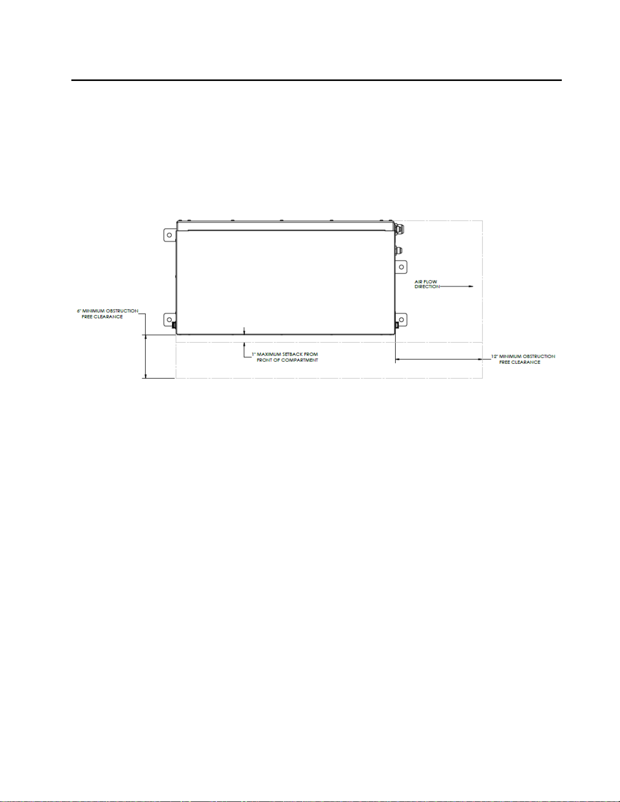
6. SPS models ER-6.2, ER-8, ER-10 and ER-110 can be mounted on top of a vehicle, in
the open, without requiring any additional coverings. Reference Error! Reference s
ource not found. for the minimum clearances around the perimeter of the generator’s
tray assemble. Also, do not position any obstructions directly in front of the system’s oil
cooler. If the system cannot be installed without maintaining the minimum clearances
as indicated, or if you have any questions relative to the installation of these systems,
contact Smart Power Systems®at (231) 832-5525.
Figure 3 –Top View of ER-6.2, ER-8, ER-10 and ER-110 Tray Assemblies
Showing Minimum Clearance for Proper Ventilation
Smart Power Systems®
A. C. MODULAR GENERATOR SYSTEM Page 15 of 52
WARNING:
Do not mount the hydraulic pump or tray assembly in any location that is not well
ventilated. External heat sources elevating the hydraulic fluid and/or the generator
temperature will result in premature wear and degraded system performance and
void the system’s warranty.
7. The tray assembly must be mounted in a position that is higher than the pump. If the
pump inlet hose is 10’ in length or less, the tray and reservoir assemblies must be a
minimum of 12” higher than the pump. If the pump inlet hose is longer than 10’,
elevate the tray and reservoir assemblies an additional 12” for every additional 10’ of
pump inlet hose length. See below for examples of minimum tray assembly elevations
above the pump:
Pump inlet hose length
Minimum tray and reservoir elevation
(above pump)
0 –10 ft.
12 inches
15 ft.
18 inches
20 ft.
24 inches
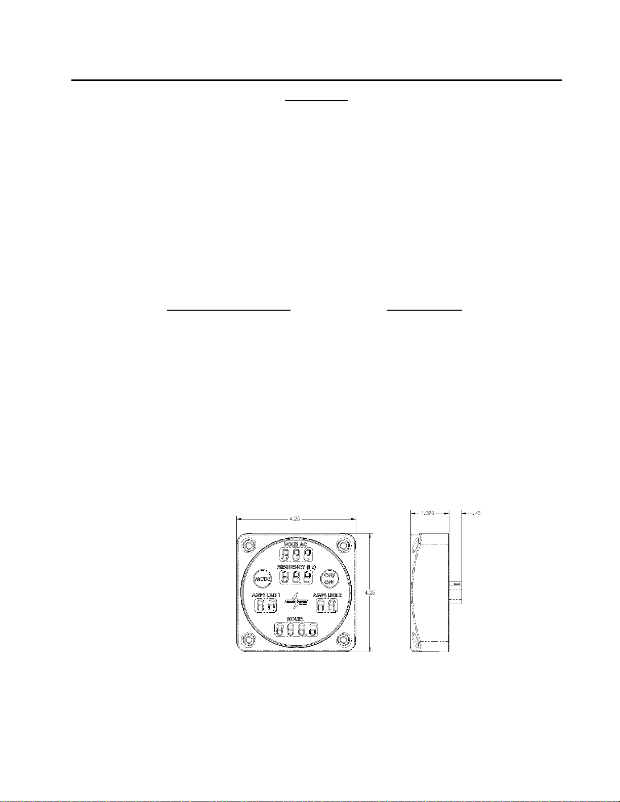
8. Locate a position to mount the SPS Command & Control Center. The ideal location for
the Command & Control Center will be in an area that is easily seen and accessed by
the generator operator. When the generator system is in use, the Command & Control
Center will continuously show the status of the generator, including faults (warnings) if
they occur. The Command & Control Center can also be used to engage and
disengage the generator. The Command & Control Center is water sealed, and
operates on low voltages so pump house mounting is permissible. A 15 ft. water
sealed harness is provided to connect the Command & Control Center to the system
controller mounted within the generator tray assembly. See Figure 44 for the
dimensions of the Command & Control Center.
Command & Control Center, P/N 1500047
Figure 4

Smart Power Systems®
A. C. MODULAR GENERATOR SYSTEM Page 16 of 52
Installation Guide
1. Mount the pump securely to the Power Take-Off (PTO). This may require attaching
a mounting bracket to the PTO housing prior to mounting the pump.
WARNING:
Always mount the hydraulic pump in a position with the pump controls up.
Mounting the pump in any other orientation will not allow hydraulic fluid in the
pump to reach the correct level before starting, causing premature wear of the
pump, thus voiding the system’s warranty. The pump and undercarriage
components will corrode if they are left unprotected. It is advisable to paint them
before completing the installation.
2. Locate and bore mounting holes for generator tray assembly as shown in Error! R
eference source not found.5. Maintain minimum clearances as indicated in,
Error! Reference source not found..
Figure 5 –Mounting Hole Pattern for ER-6.2, ER-8, ER-10 and ER-110 Assemblies
3. Mount the tray assembly as high as possible within the structure of the vehicle. The
ideal location for the generator is at the top of the truck in the dunnage area. The
manufacturer must also take sufficient precautions to ensure that the generator is
not mounted in the path of the deck gun/water cannon.

Smart Power Systems®
A. C. MODULAR GENERATOR SYSTEM Page 17 of 52
4. Mount the hydraulic generator tray securely to vehicle. Secure the generator to the
floor of the enclosure using hardware (not included), as shown in Figure 6.
1/2-13UNC Screw
1/2” Flat Washer Generator Tray
Dunnage Area
Floor
1/2” Flat Washer 1/2” Lock Washer
1/2-13UNC Nut
WARNING:
Never mount the Generator on its side or upside down. Always mount the generator
upright with its base horizontal. Improper mounting will lead to poor performance
and damage to the system and will void the system’s warranty.
Never operate an AC modular generator system that is not secured in place;
damage will result.
Do not mount the hydraulic pump or tray assembly in any location that is not well
ventilated. External heat sources elevating the hydraulic fluid and/or the generator
temperature will result in premature wear and degraded system performance and
void the system’s warranty.
Figure 6
Smart Power Systems®
A. C. MODULAR GENERATOR SYSTEM Page 18 of 52
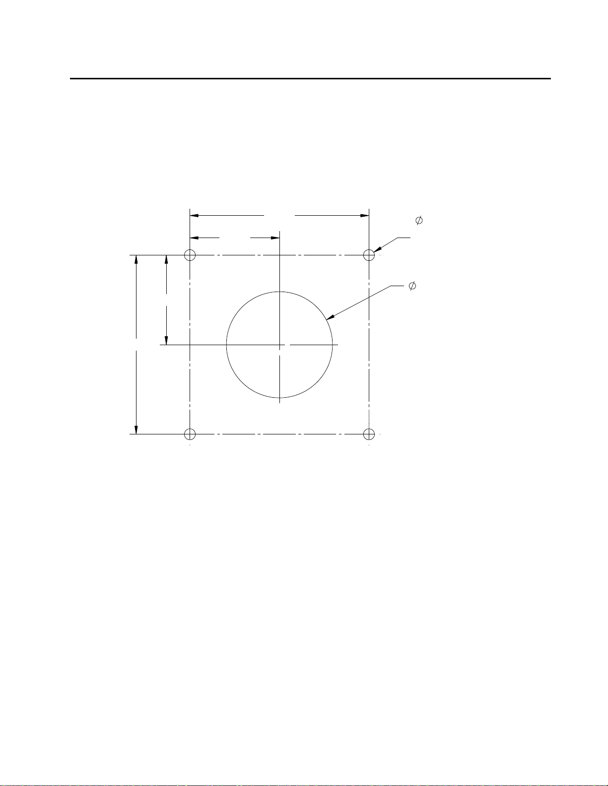
5. Mount Command & Control Center:
a. Create hole pattern as shown in Error! Reference source not found.7.
b. Mount Command & Control Center to vehicle using #10 stainless steel button
head or cap screw fasteners. Take care not to overtighten the fasteners, as
damage to the plastic Command & Control Center housing may result.
c. Connect Command & Control Center to system controller unit (Figure 8) using
p/n 3722004 harness.
Figure 7 –Command & Control Center Hole Pattern
.208
CLEARANCE HOLE
FOR #10 SCREW
4 PL.
2.000
3.375
3.375
1.688
1.688

Smart Power Systems®
A. C. MODULAR GENERATOR SYSTEM Page 19 of 52
6. Install hoses and tighten hose ends, using the Hose Installation Guidelines. See
Figure 8 for connection locations.
Figure 8 –ER-6.2, ER-8, ER-10 and ER-110 Interfaces
This manual suits for next models
3
Table of contents
Other Smart power Inverter manuals

Popular Inverter manuals by other brands

Moseley Associates
Moseley Associates SCG-3T instruction manual

Champion Power Equipment
Champion Power Equipment 100246 Owner's manual & operating instructions

Powtran
Powtran PI160 Series manual

Mitsubishi
Mitsubishi FR-A800 manual

National Semiconductor
National Semiconductor LM7705 manual

Analytic Systems
Analytic Systems IPS1500 Series Installation & operation manual


