Error: No Tachometer
If the Tachometer should fail your machine will shut down for safety
reasons. This can also be caused by a stalled motor or unplugged
Tachometer cable. The No Tachometer Error message will be flashed
across the top line. It is possible to run the machine without a
Tachometer although the accuracy of the speed may vary. To do this
follow the prompt and select yes to run in open loop mode.
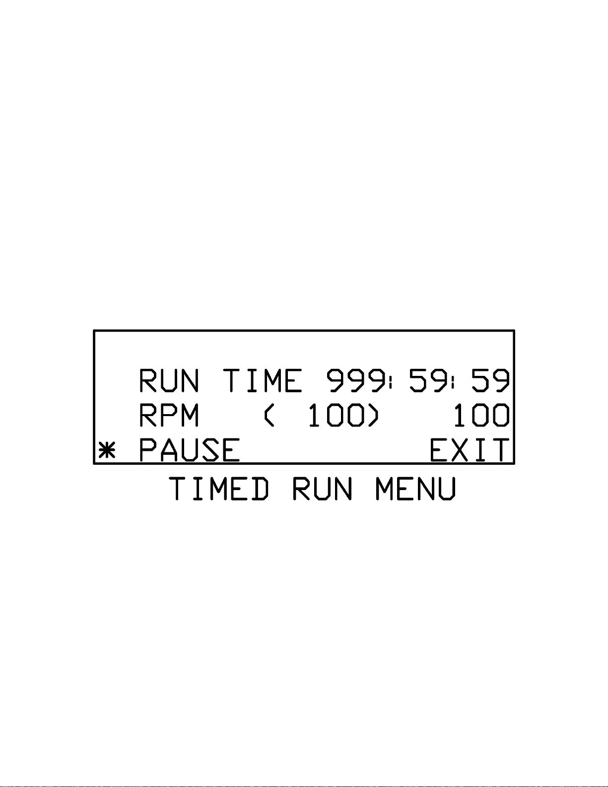
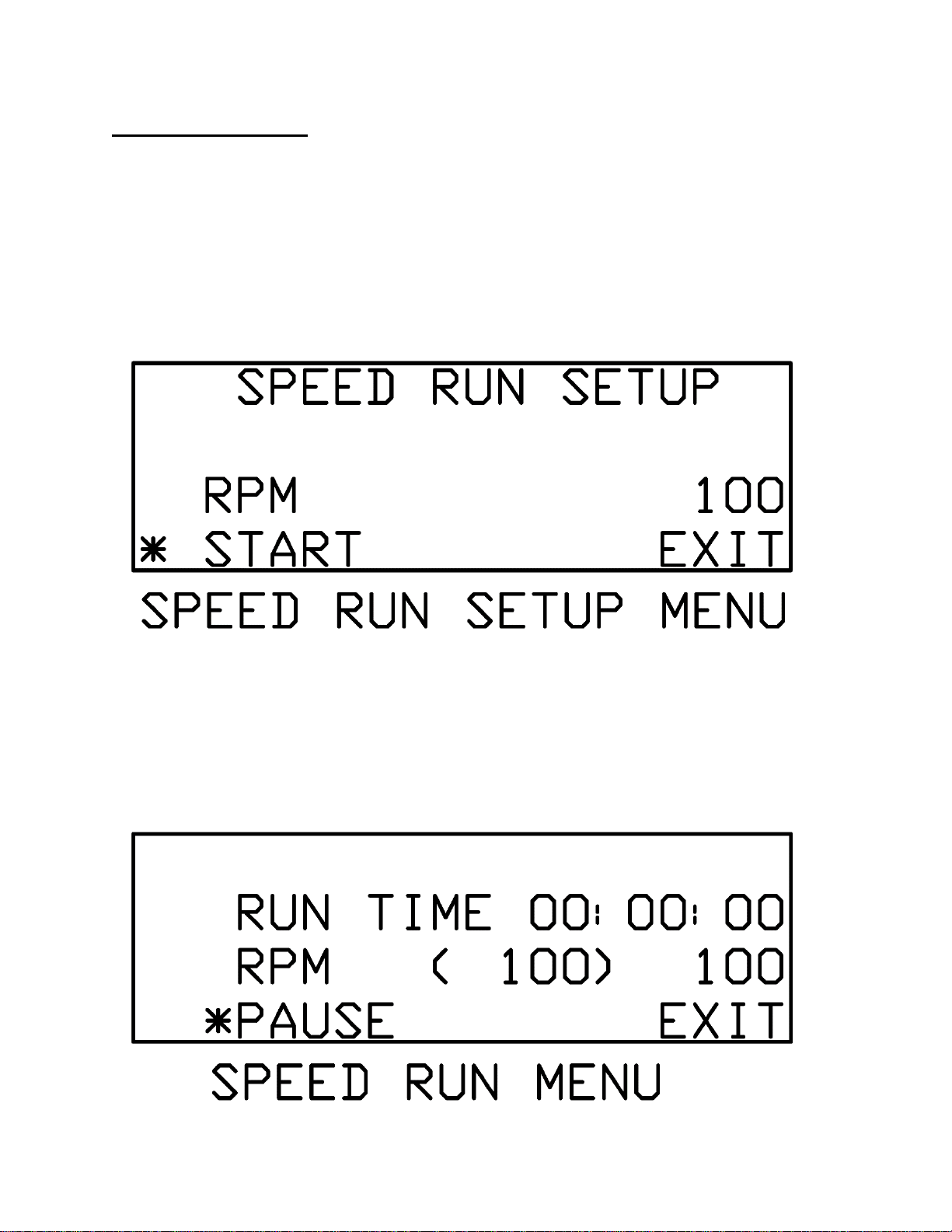
Note: All run menus will have two speeds listed. The leftmost speed
will be displayed inside parenthesis. This is the target speed controlled
by the user. The shaker will attempt to match this speed and should do
so within ten seconds after making an adjustment. The rightmost speed
is the tachometer reading, which shows the user what the shaker is
actually running at. The tachometer reading will not necessarily match
the target speed at all times, but is guaranteed to be within +/- 1% RPM.
Note: Reciprocating shakers will display OSC (oscillations) instead of
RPM (revolutions per minute).
Note: Use slowest speed necessary to produce required shaking
action.
If you have any doubts or inquiries concerning operation contact your
supplier or Eberbach Corporation technical service.
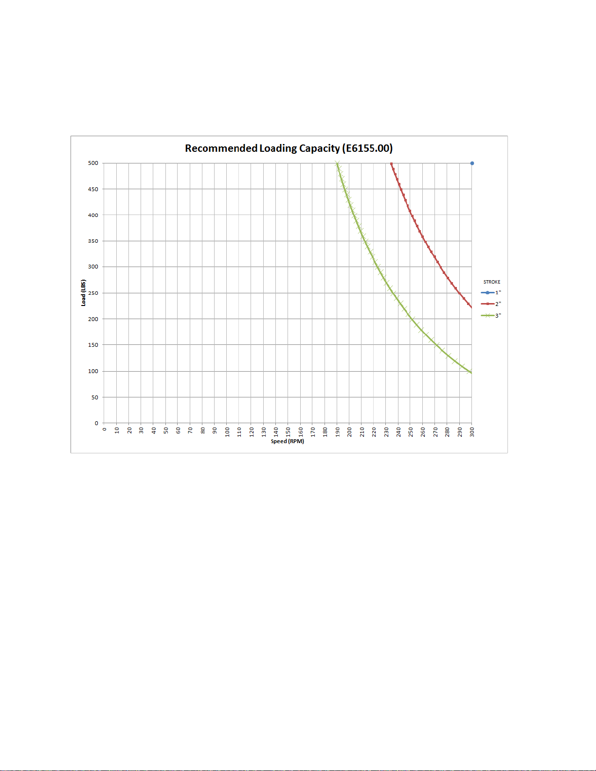
LOADING: