EBERBACH EL680.Q Installation instructions

USE AND CARE FOR CATALOG NUMBER:
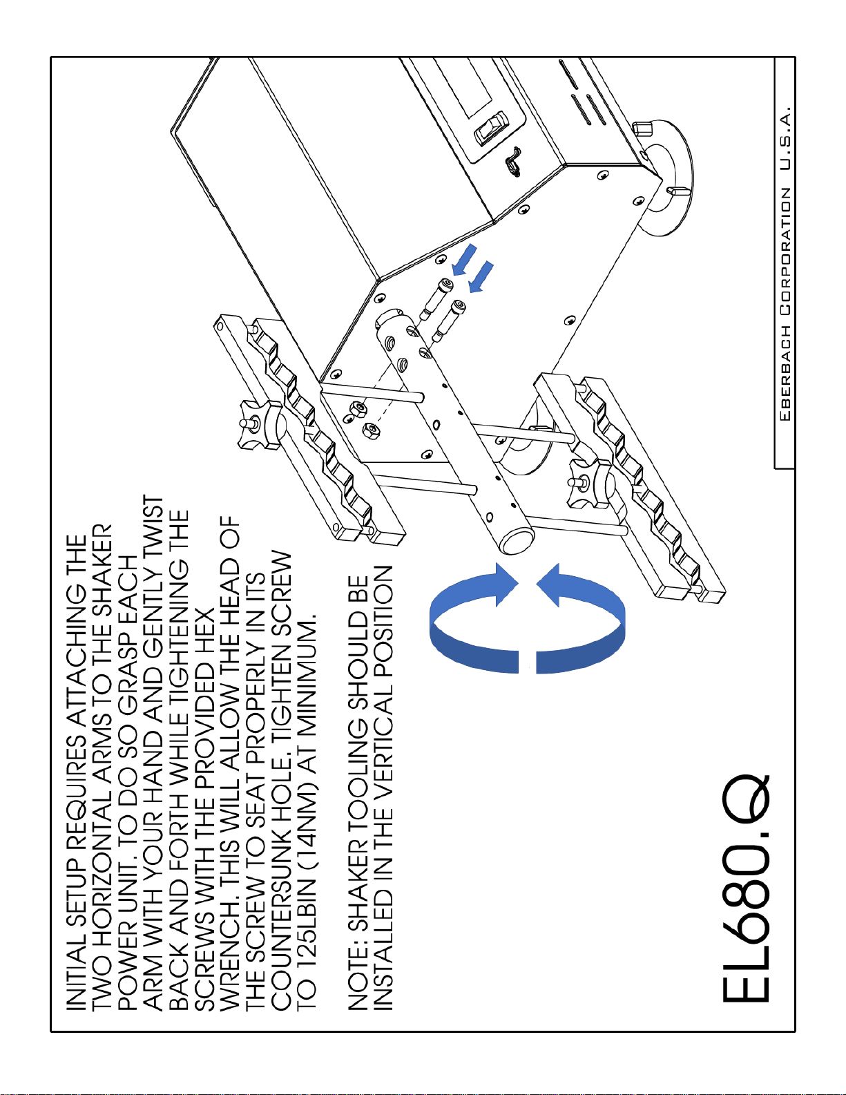
EL680.Q Digital Variable Speed Reciprocating Shaker -
115V - 50/60 Hz
CAUTION!
UNPLUG THE POWER CORD BEFORE DOING ANY
MAINTENANCE ON THIS MACHINE.
FAILURE TO DO SO MAY CAUSE INJURY
!!THE USER OF THIS DEVICE IS RESPONSIBLE FOR OBTAINING THE
PROPER PERSONAL PROTECTIVE EQUIPMENT DEPENDING ON THE
MATERIAL BEING PROCESSED!!
IF THE EQUIPMENT IS USED IN A MANNER NOT SPECIFIED BY THE
MANUFACTURER, THE PROTECTION PROVIDED BY THE EQUIPMENT
MAY BE IMPAIRED.
SERVICE ON THE UNIT SHOULD BE PERFORMED BY QUALIFIED /
TRAINED PERSONELL ONLY.
INITIAL PREPARATION:
Place shaker on a level table or bench.
NOTE: This unit should be operated by trained personnel.
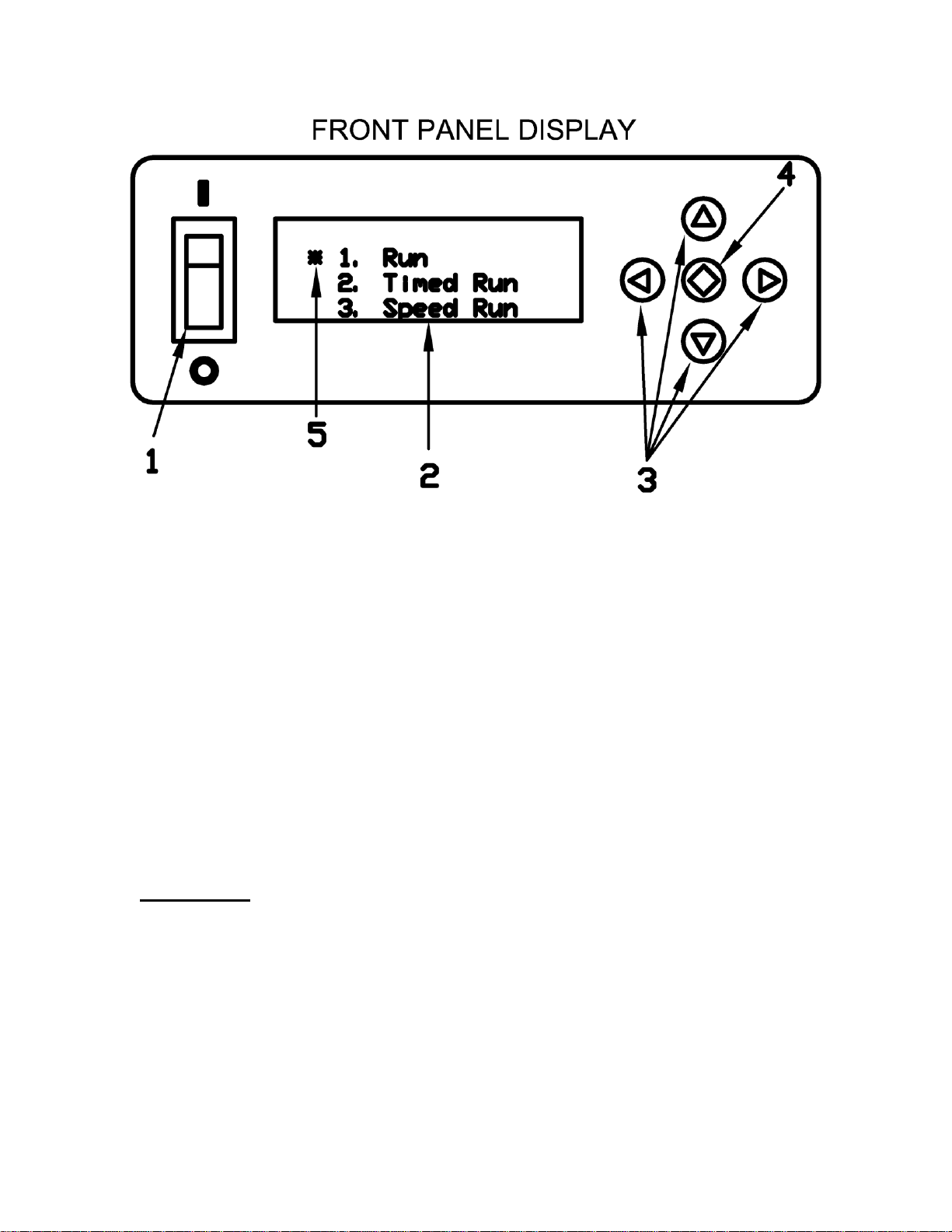
With the power switch on the front panel in the off position ( 0 ), plug the line cord
into a 115 Volt, 50/60 Hz source. Turn shaker on by moving switch to the On
position ( I ).
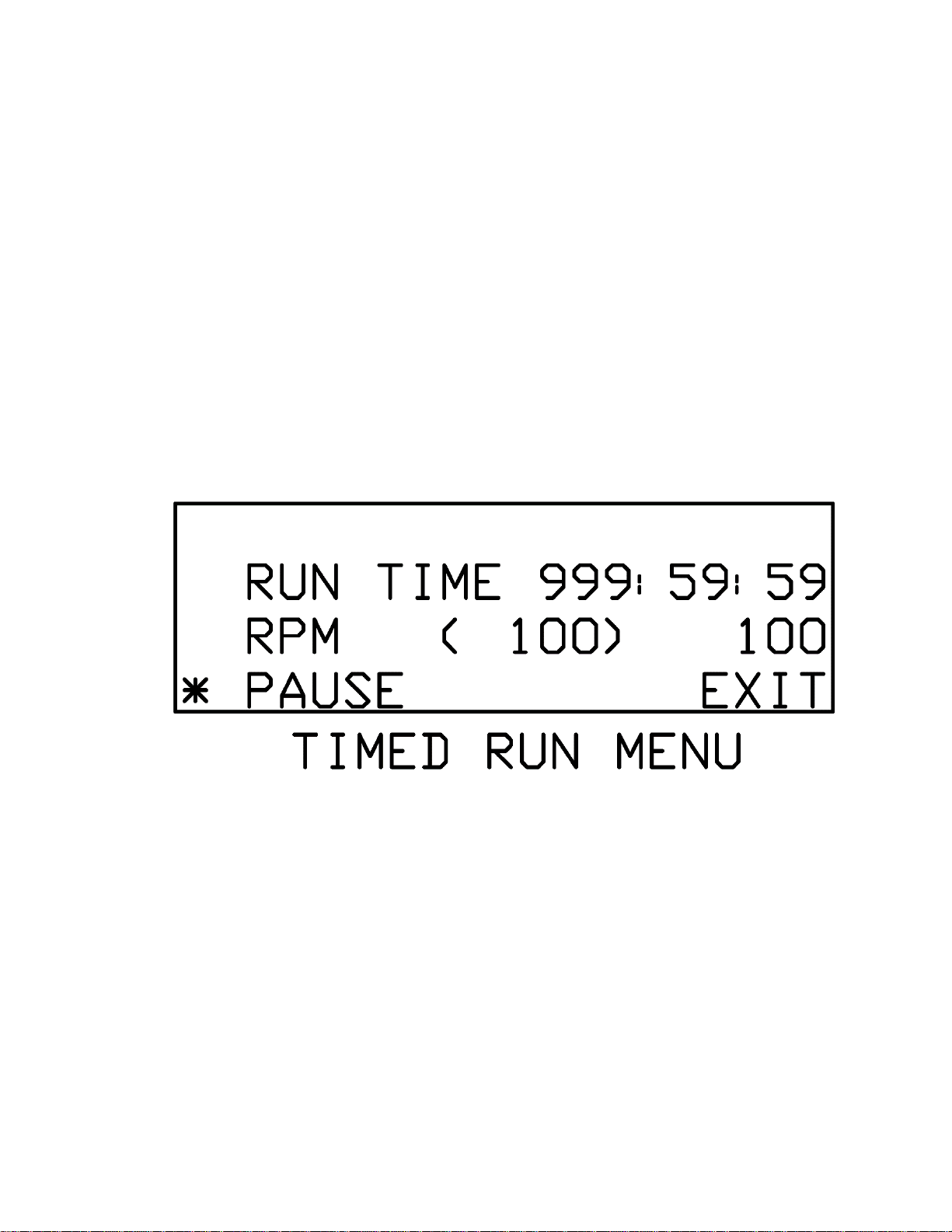
NOTE: Speed adjustments should be made only when the shaker is operating.
Use slowest speed necessary to produce required shaking action.
NOTE: This unit emits less that 70.0 dB(A).
CAUTION: Extra effort may be needed when lifting machine due to suction
adhesion with table and rubber feet.
IN AN EMERGENCY TURN OFF UNIT OR UNPLUG AC CORD

USE AND CARE FOR CATALOG NUMBER:
EL680.Q Wrist Action Shaker
Variable Speed with Timer and Tachometer
100-600 +/-2 opm, 115V- 50/60 Hz
GENERAL INFORMATION
1) Handle this unit with care. Unpack and check that the contents coincide
with the packing-list. If any part is damaged or missing, please advise the
distributor immediately.
2) Do not install or use this equipment without first reading this manual.
3) This manual should always be attached to the equipment and made
available to all users.
4) If you have any doubts or inquiries, please contact your supplier or
Eberbach Corporation technical service.
5) Do not use the apparatus with liquids which can give off vapors capable
of making explosive mixtures.
PACKING LIST
The standard equipment consists of the following components:
Description Qty
Wrist Action Shaker 1
Arms 2
Clamps 8
Power Cord 1
Allen Wrench 3/16 1
Allen Wrench 3/32 1
Use and Care Manual 1

EQUIPMENT DESCRIPTION
Wrist Action Shaker: Electronic regulation between 100 and 600 oscillations
per minute. Oscillation amplitude is 9mm. Easily detachable arms equipped
with 8 clamps for attaching and processing up to 8 samples at one time.
TECHNICAL FEATURES
Voltage supply 115V, 50/60 Hz
Height 18 in
Length 14 in
Width 36 in
Maximum Capacity 4 kg (8.8 lbs)
Oscillations per minute 100-600 +/-2
Power Consumption 0.7 Amps
INSTALLATION
1) Place the apparatus on a flat, horizontal, level surface with enough
stability to resist its own vibrations.
2) Fit the arms with clamps to the shaker side shaft so that the screws
tighten against the flat surface of the shaft.
CAUTION!!! IMPORTANT FOR YOUR SAFTEY
Be sure that the voltage supply is the same as the one indicated on the serial
tag.
Do not shake products capable of making an explosive mixture.
Do not use the apparatus if it is not grounded properly.


1) Power Switch
2) Liquid Crystal Display (LCD)
3) Directional Pad (D-Pad)
4) Enter Button
5) Cursor
Operation: Press the Power Switch down into the ON position.
The LCD should light up and show the main menu. There are three
different run modes to choose from. Select a run mode by moving
the Cursor (using the D-PAD) and press the Enter Button.

Run Mode: The shaker will begin the run mode at its lowest speed.
The speed shown in parenthesis (xxxx) is the set speed controlled by
the user. The speed listed to the right is the tachometer read out or
the actual speed of the shaker in real time. The speed can be
increased/decreased by pressing and holding the up/down arrows on
the D-PAD. The longer the button is held down the faster the speed
will increase/decrease. Once engaged the timer will begin counting
all the way up to 999 hours before the timer overflows back to zero.
To pause the shaker move the Cursor to the PAUSE item by
pressing the left arrow on the D-PAD and press the Enter Button.
The clock will pause at its current time and the shaker will gradually
come to a complete stop. The clock and shaker can be resumed at
its current time and speed by selecting RESUME and pressing the
Enter Button. To go back to the main menu move the Cursor to the
EXIT item by pressing the right arrow on the D-PAD and then press
the Enter Button.

Timed Run Mode: The timed run mode features a count down timer
that automatically shuts the shaker off when the time runs out. When
selected the user will be taken to the Timed Run Setup Menu and will
need to input the run time in hours, minutes, seconds and select the
speed for the run. The left/right arrows on the D-PAD can be used to
move the cursor between hours, minutes or seconds and the up and
down arrows can be used to set the time. The longest run time
allowed is 999:59:59. Once the time is set move the Cursor down by
pressing the right arrow on the D-PAD until the Cursor is next to the
RPM line item. The speed can be set using the up and down arrows
on the D-PAD. Now that the data is set navigate the Cursor to the
START line item using the left/right arrows on the D-PAD and press
the Enter Button.

After selecting START the shaker will begin at the selected speed
and the timer will begin counting down. The speed can be adjusted
in real time using the up/down arrows on the D-PAD. The speed
shown in parenthesis is the target speed controlled by the user and
the speed listed to the right is the actual speed as read by the
tachometer. The shaker and countdown timer can be paused and
resumed. Move the Cursor to the line item PAUSE by pressing the
left arrow on the D-PAD and then press the Enter Button. Exiting
the Timed Run Menu will bring the user back to the Timed Run Setup
Menu.

Speed Run Mode: The speed run allows the user to program in a
set run speed. Once engaged the timer will begin counting all the
way up to 999 hours before the timer overflows back to zero. Select
the speed run mode from the main menu and press the Enter
Button. The user will be prompted with the speed run setup menu.
Set the desired speed using the up/down arrows on the D-PAD. The
left/right arrows can be used to move the Cursor between START
and EXIT. EXIT will take the user back to the main menu. Keep the
Cursor next to the START line item and press the Enter Button.
The user will now be taken to the speed run menu. The shaker will
begin at the speed selected in the setup menu. The speed run menu
behaves in the same way as the run menu with one exception.
Pressing EXIT will not take the user back to the main menu instead
pressing EXIT will take the user back to the speed run setup menu.

Restoring the Factory Settings:
During the course of operation the machine may need to be reset
to its factory settings. To do so the user must press and hold the
green Enter Button. Next the user must turn the Power Switch
on, while continuing to hold the Enter Button. After a few seconds
the user will be presented with the utilities menu.
Navigate the Cursor to the top line item marked “1. Presets
Rev_XX” and press the Enter Button. The user will now be
presented with the presets menu.

The Cursor should be next to the line item “Model : xxxx” use the
up/down arrow buttons, on the D-PAD, to select EL680Q.The
models are listed numerically with the smallest numbers at the bottom
and the largest numbers at the top. If the line reads “Model: Empty”
then press and hold the down arrow button to get back into the model
numbers. Once the user has selected the correct model number,
press the right arrow button on the D-PAD. Use the up arrow button
on the D-PAD to change the motor setting to “Bodine.” Navigate the
Cursor down to the save line item by pressing the right arrow button
on the D-PAD. Press the Enter Button to save the preset settings.
The user will now be back at the utilities menu. Navigate the Cursor
down to the last line item “4. Exit” and press the Enter Button. The
machine has now been reset to its factory settings.

Note: There may be instances when the memory can become
corrupt even though the presets menu appears to be correct. The
problem can result in false speed values during run operation. If the
user navigates to the preset menu and the settings match the picture
shown above, navigate the Cursor down to save and press the Enter
Button anyways. This will ensure that the maximum and minimum
speed values are correct.
Note: All run menus will have two speeds listed. The leftmost speed
will be displayed inside parenthesis. This is the target speed
controlled by the user. The shaker will attempt to match this speed
and should do so within ten seconds after making an adjustment.
The rightmost speed is the tachometer reading, which shows the user
what the shaker is running at. The tachometer reading will not
necessarily match the target speed at all times, but is guaranteed to
be within +/- 5 RPM.
Note: Reciprocating shakers will display OSC (oscillations) instead
of RPM (revolutions per minute).
Note: Use slowest speed necessary to produce required shaking
action.
Note: Do not rotate machine by hand as doing so may corrupt the
digital memory and require a factory reset.
If you have any doubts or inquiries concerning operation contact your
supplier or Eberbach Corporation technical service.

Maintenance
CLEANING:
Before removing the casing, disconnect the apparatus from the mains.
The manipulation of the internal electronic circuits of the apparatus
unauthorized personnel can cause irreparable damage to the apparatus.
When cleaning the plastic, use alcohol with a cotton cloth. When cleaning the
painted metal case, use warm soap and H2O solution.
FUSE REPLACEMENT:
The motor fuse is a 1.25A (1.25”x0.25”) Time Delay Fuse. The line fuses are
3A (5x20mm) Time Delay Fuse. Preventative maintenance has set the fuse to
blow if the motor is over worked. The problem is generally in extreme wear of
the bearings or an object obstructing the shaking action.
NOTE: If replacement fuse blows almost immediately, repairs may be
necessary.
If you have any doubts or inquiries concerning operation contact your supplier or
Eberbach Corporation technical service.

BELT INSPECTION AND REPLACEMENT:
Inspect belt periodically and replace if broken or if the cords are exposed or
frayed. Small outer fabric breaks are not harmful.
Removal of the drive belt may require the adjustment or removal of the motor
and/or the large drive pulley. Installation of a new belt is as follows:
1. Unplug unit to avoid shock and/or electrical component damage.
2. Remove the left side panel to expose the motor and other components.
3. Take note or mark the location of the motor along the adjustable slots in
base plate.
4. Loosen the socket (“allen”) screws that fasten the motor to the base
plate.
5. Slide the motor towards the large pulley to allow the belt to slacken.
6. Remove belt and install new belt with identical number of teeth.
7. Adjust tension on belt. Note: cogged style belt does not need excessive
tension.
MOTOR:
In the case of a high duty cycle, brushes should be inspected and/or replaced
at determined intervals (12-24 months). Brushes can be removed by carefully
following the steps outlined below:
1. Remove the left side panel. Once disassembled you can perform the
maintenance to the brushes.
2. Unscrew the black plastic brush holders located on each side of the motor.
Be careful not to lose the inside spring when unscrewing brush holders.
3. Inspect brushes and clean or replace as necessary. Replace brushes if
worn to less than 1/8”.
If you have any doubts or inquiries concerning operation contact your supplier or
Eberbach Corporation technical service.

ELP680.Q REPLACEMENT PARTS LIST
PartNo DESCRIPTION QTY.
4112 BEARING 2
4113 BEARING 2
4259 16" TIMING BELT 1
4400.3 4MM X 20MM KEY 1
4508 TIMING PULLEY, 22 TEETH 1
5339.5 INTRENAL SNAP RING FOR 1-3/8" BORE 2
5528 3.75" SUCTION CUP W/ 5/16-18 THREADED POST 4
5535.5 RUBBER GROMMET 1
5631 3/32 STANDARD ALLEN WRENCH 1
5645 5/16 STANDARD ALLEN WRENCH 1
6010.7 30W POWER SUPPLY 1
6063.2 CABLE TIE 3
6102 OVERLAY 1
6112 FUSE, 1.25AMP TIME DELAY 1
6113 FUSE, TIME DELAY 3A 2
6131.1 FUSE HOLDER 1
6217 FEMALE QUICK DISCONNECT 1
6220 CABLE TIE HOLDER WITH ADHESIVE BACKED 3
6267.2 CONNECTOR 1
6278 AC INLET 1
6333 MOTOR CONTROLLER 1
6507.1 ROCKER SWITCH 1
6730 7 TERMINAL GROUNDING BLOCK 1
6851 DISPLAY BOARD 1
6855 USB BOARD 1
6969 MOTOR, 1/8HP 1
7397 #2-56 X 1/4" S/S PAN HD. MACHINE SCREW 1
7398 #2-56 X 5/16" S/S PAN HD. MACHINE SCREW 1
7406.7 #6-32 X 3/16" S/S PAN HD. MACHINE SCREW 2
7568 #4-40 X 1/4" S/S PAN HD. MACHINE SCREW 4
7954 #5-40 X 3/8" S/S FLAT HD. SOCKET SCREW 2
8050 #4-40 x 3/8" S/S PAN HD. MACHINE SCREW 6
8277.1 #8-32 X 1/2" S/S TRUST HD. SCREW 4

8277.11 #10-32 X 1/4" S/S TRUST HD. SCREW 4
8285 #8-32 X 1/4" S/S TRUST HD. SCREW 28
8321.5 #10-32 X 1/4" SET SCREW 8
8554 3/8"-16 X 1" HEX HEAD SCREW 4
8586 1/4"-20 X 1/2" SOCKET HD. SCREW 2
8587 1/4"-20 X 5/8" SOCKET HD. SCREW 4
8588.1 1/4"-20 X 1" SOCKET HD. SCREW 1
8588.3 1/4"-20 X 1-1/4" SOCKET HD. SCREW 5
8589 1/4-20" X 1-1/2" SOCKET HD. SCREW 6
8607.2 1/4"-20 X 5/16", 1" SOCKET SHOULDER SCREW 4
9207 #5-40 NYLON-INSERT HEX LOCKNUT 2
9235 #8-32 S/S MACHINE SCREW NUT 2
9261 1/4"-20 GRADE 5 EXTRA-WIDE HEX NUT 4
9283 3/8"-24 GRADE 5 HEX NUT 2
9435 #12 SAE WASHER 2
9950 BLUE LOCTITE 242 1
EL680.Q.009 MOTOR CONTROLLER SPLASHGUARD 1
ELP680.HD.211 RIGHT SIDE COLUMN 1
ELP680.HD.212 PULLEY BLOCK 1
ELP680.HD.217 LEFT SIDE COLUMNS 1
ELP680.HD.315 CROSS STRAP 1
ELP680.HD.525A CRANK BLOCK BEARING ASSEMBLY 1
ELP680.HD.S.202 BAR ARM 1
ELP680.Q.018 CONNECTING PIN 1
ELP680.Q.210 BASE WEIGHT 1
ELP680.Q.214 DRIVE CLAMP 1
ELP680.Q.301 DRIVEN SPROCKET 1
ELP680.Q.303 RIGHT SHAFT EXTENSION 1
ELP680.Q.304 LEFT SHAFT EXTENSION 1
ELP680.Q.323 60 TOOTH TACH WHEEL 1
ELP680.Q.502A LOWER CLAMP ASSEMBLY 2
ELP680.Q.503A UPPER CLAMP ASSEMBLY 2
ELP680.Q.508A ECCENTRIC SHAFT ASSEMBLY 1
ELP680.Q.652A WIRING HARNESS 1
ELP680.Q.SS.324 MOTOR BRACKET 1

ELP680.Q.SS.325 TACH BRACKET 1
ELP680.Q.SS.507A REAR PANEL ASSEMBLY 1
ELP680.SS.220 BASE PLATE 1
ELP680.SS.223 SIDE PANEL 2
ELP680.SS.508A CASE ASSEMBLY 1
If you have any questions or inquiries concerning installation or ordering of replacement parts
please contact your supplier or Eberbach Corporation Technical Service @ 1-800-422-2558.


Table of contents
Other EBERBACH Paint Sprayer manuals