Ebmpapst ECI-42 K1 Series Wiring diagram

the engineer’s choice
Drives for Siemens partner range
SIMATIC MICRO-DRIVE
Translation of original operating instructions (ENU)

2/28 Item no.: 601.2055 · ENU · Change V1.1 · Release 2022-10-11
Drive conceptsDrive concepts
SIMATIC MICRO-DRIVESIMATIC MICRO-DRIVE
Content
1 Introduction ............................................................................................................... 5
1.1 Foreword........................................................................................................................................................5
1.2 Target group ..................................................................................................................................................5
1.3 Written styles in this document ...................................................................................................................5
1.4 Warning notices and notices ........................................................................................................................5
2 Safety information..................................................................................................... 6
2.1 General safety information ...........................................................................................................................6
2.2 Documentation ..............................................................................................................................................6
2.3 Mechanical safety..........................................................................................................................................6
2.4 Legal requirements .......................................................................................................................................6
...............................................................................................................................7
2.6 Safety of persons ..........................................................................................................................................7
2.7 Electric/electromagnetic safety....................................................................................................................7
2.8 Intended use ..................................................................................................................................................8
2.9 Improper use..................................................................................................................................................8
...................................................................................................................9
2.11 Transport and storage...................................................................................................................................9
2.12 Behavior in the event of malfunctions and irregularities ...........................................................................9
3 Description ................................................................................................................ 10
3.1 Description of the drives for SIMATIC MICRO-DRIVE.................................................................................10
............................................................................................................................10
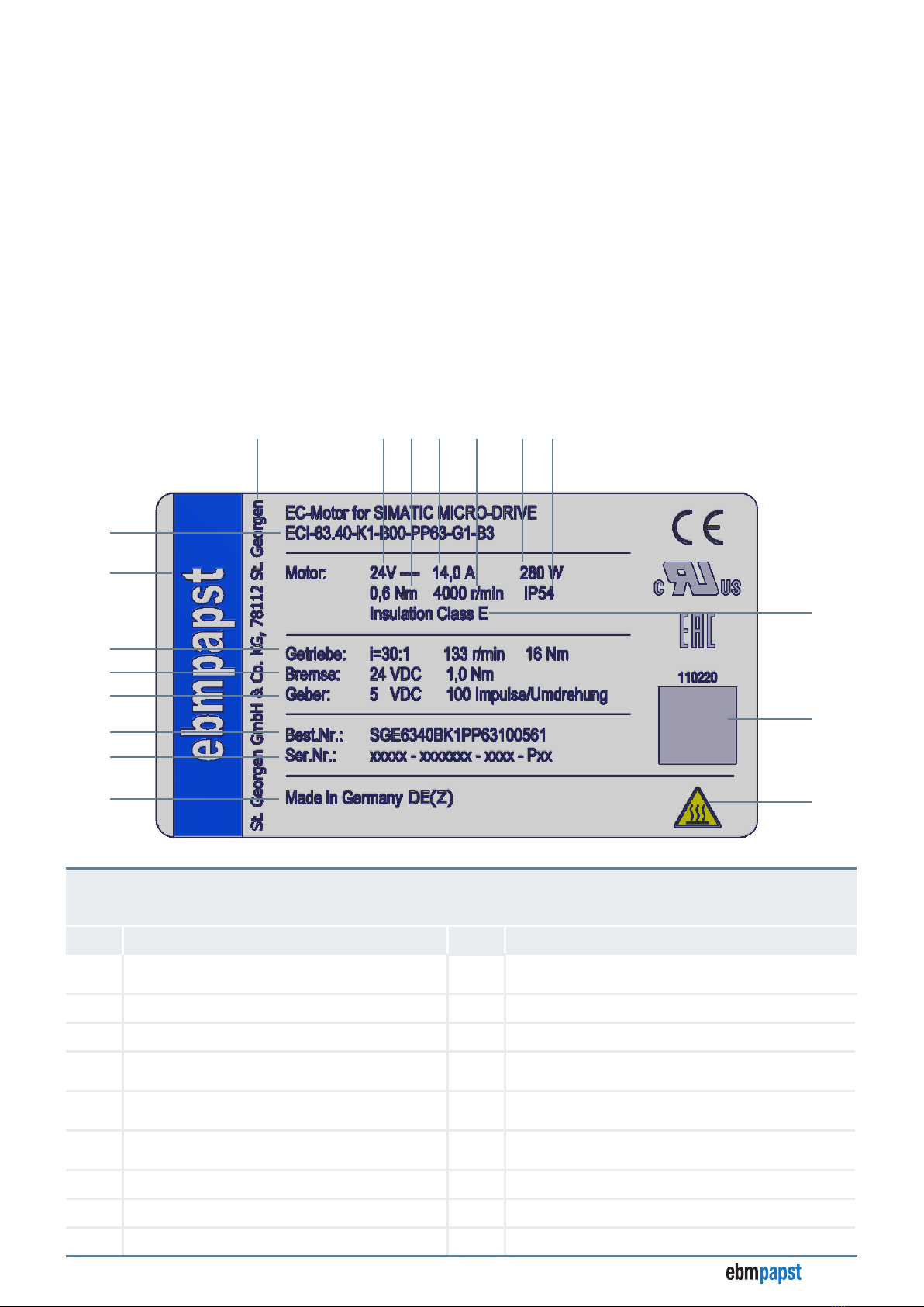
3.2.1 Nameplate ................................................................................................................................................. 10
.......................................................................................................................... 11
3.2.3 Scope of delivery....................................................................................................................................... 11
3.3 Device view ....................................................................................................................................................12
4 Technical data............................................................................................................ 13
4.1 ECI-42.XX-K1..................................................................................................................................................13
4.2 ECI-63.XX-K1..................................................................................................................................................14
4.3 ECI-80.XX-K1..................................................................................................................................................15
4.4 Encoder system.............................................................................................................................................16
.............................................................................................................................................16
4.6 Dimensional drawings ..................................................................................................................................17
..................................................................................................................... 17
........................................................................................................ 17

3/28
Item no.: 601.2055 · ENU · Change V1.1 · Release 2022-10-11
Drive conceptsDrive concepts
SIMATIC MICRO-DRIVESIMATIC MICRO-DRIVE
..................................................................................................................... 18
........................................................................................................ 18
..................................................................................................................... 19
........................................................................................................ 19
5 Installation ................................................................................................................. 20
....................................................................................................................................21
5.2 Mechanical installation .................................................................................................................................21
5.3 Electrical installation ....................................................................................................................................22
5.3.1 ECI-42.XX-K1 and ECI-63.XX-K1 interfaces ............................................................................................ 22
5.3.2 ECI-80.XX-K1 interfaces............................................................................................................................ 23
5.4 Schematic overview ......................................................................................................................................24
6 Maintenance and error handling .............................................................................. 25
6.1 Cleaning .........................................................................................................................................................25
6.2 Maintenance and repair ................................................................................................................................25
6.3 Disposal .........................................................................................................................................................25
.............................................................................................................................................. 25
6.3.2 Component disposal................................................................................................................................. 26
7 EU declaration of conformity.................................................................................... 27

4/28 Item no.: 601.2055 · ENU · Change V1.1 · Release 2022-10-11
Drive conceptsDrive concepts
SIMATIC MICRO-DRIVESIMATIC MICRO-DRIVE
Disclaimer
Contents of operating instructions
These operating instructions have been created with care. However, ebm-papst assumes no liability for the up-to-dateness,
correctness, completeness, or quality of the information provided. Liability claims towards ebm-papst which relate to damage of
a material or non-material nature which was caused by use or non-use of the information presented or by the use of incorrect
and incomplete information are categorically excluded insofar as there is no evidence of deliberate or grossly negligent culpabili-
ty on the part of ebm-papst.
Version Date Change description
V1.1 2022-10-11 EU declaration of conformity Kap. 7 updated
ebm-papst St. Georgen
GmbH & Co. KG
Hermann-Papst-Strasse 1
78112 St. Georgen
Copyright
ebm-papst St. Georgen
GmbH & Co. KG
Hermann-Papst-Strasse 1
78112 St. Georgen
ebm-papst has sole copyright. Duplicating this document or using it without the express consent of the author is prohibited.
The operating instructions must be available to the user at all times, to ensure the device is used safely. They must be kept at
an easily accessible location at the place of installation, where they can be viewed at all times.
Application
Safety regulations must be observed when using the servomotors. Read these operating instructions carefully before you start
working on the drive. Observe the hazard and warning notices to avoid the risk of injury or malfunctioning.
These operating instructions form part of the servomotor. The drive is only to be sold or passed on together with the operating
instructions. Safety regulations may be duplicated and distributed to inform about potential dangers and their prevention.
ebm-papst is always looking to advance and enhance its products. As a result, products may differ from these operating
instructions. The user must check this before use and take into account any deviations.
Subject to change.
You can find the respective current version of these operating instructions on our homepage: www.ebmpapst.com
Siemens product partner range
These operating instructions set out the products from the manufacturer Siemens AG in order to provide more details on the
application. The product designation "SIMATIC MICRO-DRIVE" is a registered brand name/trade mark of Siemens AG.

5/28
Item no.: 601.2055 · ENU · Change V1.1 · Release 2022-10-11
Drive conceptsDrive concepts
SIMATIC MICRO-DRIVESIMATIC MICRO-DRIVE Introduction
1 Introduction
1.1 Foreword
These operating instructions describe the possible uses, installation and operation of the servomotors from the Siemens product
partner range for SIMATIC MICRO-DRIVE for the safety extra-low voltage range. When installing and operating the servomo-
tors, all of the safety information listed in Chapter 2 must be adhered to. Abroad, the corresponding laws, guidelines, and regula-
tions of the relevant country also apply.
Read these operating instructions carefully before you start working on the drive. Observe the following warning notices in order
to avoid risk of injury or malfunction of the drive.
1.2 Target group
These operating instructions are only intended for authorized specialist personnel with knowledge of electronics and mechanics
(see chapter “2.5 Personnel qualifications” on page 7). Commissioning, installation, maintenance, and other work on or in
connection with the drive must only be carried out by these groups of people.
1.3 Written styles in this document
In these operating instructions, the meaning of certain sections is indicated through various means.
Descriptive text is shown without a preceding symbol.
• Text preceded by a dot (•) indicates a list introduced by a heading.
Underlined blue text indicates a cross reference, which can be clicked on in the PDF document. Upon doing so, the screen will
jump to the relevant section of the document.
1.4 Warning notices and notices
Warning notices and notices are always shown before an instruction where carrying out the action could result in a hazard or
material damage.
In this documentation, the following warning notices are used:
DANGER
Hazard
This notice indicates a hazard with a high level of risk that will directly result in death or severe bodily injury if
it is not avoided.
→This arrow highlights a corresponding precautionary measure in order to prevent the hazard.
WARNING
Hazard
This notice indicates a hazard with a moderate level of risk that may possibly result in death or severe bodily
injury if it is not avoided.
→This arrow highlights a corresponding precautionary measure in order to prevent the hazard.
CAUTION
Hazard
This notice indicates a hazard with a low level of risk that may result in light or moderate bodily injury and
material damage if it is not avoided.
→This arrow highlights a corresponding precautionary measure in order to prevent the hazard.
Notices contain information that is particularly important at the relevant point or make the operating steps described easier.
They are emphasized as follows:
NOTICE
This notice provides you with recommendations for use and helpful tips.

6/28 Item no.: 601.2055 · ENU · Change V1.1 · Release 2022-10-11
Drive conceptsDrive concepts
SIMATIC MICRO-DRIVESIMATIC MICRO-DRIVE
Safety information
2 Safety information
The servomotors have been developed based on the state of the art for electronics and electrical engineering, as well as
recognized guidelines for the safety and protection of users. See also chapter “2.4 Legal requirements”.
The drive may only be operated, installed, maintained, and put into operation by authorized specialist personnel who have read
and understood these operating instructions in full. The drive must be used with due care and in compliance with the safety
information outlined in these operating instructions and the country-specific applicable regulations.
2.1 General safety information
Always observe the following safety information, regardless of the specific operating conditions:
• Before you start working with the drive, switch it off and secure it from switching itself on again.
• Before opening the drive or entering the danger zone, bring all of the drives to a standstill and secure them from switching
themselves on again.
• Do not modify or convert the drive, or fit any attachments to it, without approval from ebm-papst.
• Commissioning may only take place following full verification of compliance with all relevant legal requirements, guidelines
and application-related safety regulations (e.g. accident prevention regulations).
• The safety hazards associated with the drive must be reassessed following installation in the end application.
• Keep the workplace clean and tidy. Untidiness in the work area increases the risk of accidents.
2.2 Documentation
When using the drive in conjunction with the components from the Siemens product partner range for SIMATIC MICRO-DRIVE
for the safety extra-low voltage range, the relevant operating instructions must also be observed. In addition to these operating
instructions, the "TIA Selection Tool" from Siemens is required for setting and parameterization.
You can find further information on the products from the Siemens product partner range in the product catalog "Drive Concept
for SIMATIC MICRO-DRIVE" on our homepage: www.ebmpapst.com
2.3 Mechanical safety
• Only carry out work when the system/machine is at a standstill.
• Ensure the drive is cooled sufficiently.
• Only ever remove the protective devices for repair and assembly work.
2.4 Legal requirements
The motor components meet the requirements according to:
• EMC 2014/30/EU
• RoHS Directive 2011/65/EU
• REACH 1907/2006

7/28
Item no.: 601.2055 · ENU · Change V1.1 · Release 2022-10-11
Drive conceptsDrive concepts
SIMATIC MICRO-DRIVESIMATIC MICRO-DRIVE Safety information
2.5
The following qualification requirements are specified in these operating instructions:
• Authorized specialist personnel: People who have been trained by the operator about potential hazards when carrying out
their assigned tasks and activities, in compliance with the associated documentation, in particular the safety and warning
notices contained therein. Due to their experience and training, authorized specialist personnel are able to avoid potential
risks and hazards when dealing with the drives or the application.
2.6 Safety of persons
• Provide sufficient protection against accidental contact (e.g. cover electrical contacts).
• Do not wear loose clothing or jewelery.
• Keep hair, clothing, and gloves well away from rotating components.
• Use personal protective equipment (e.g. hearing protection, thermal gloves).
2.7 Electric/electromagnetic safety
NOTICE
The drive is a built-in component that is operated in conjunction with the Siemens drive controllers (PDC
(=Profi Drive Control) or F-TM ServoDrive) and the cables defined for this by Siemens. The specifications for
electromagnetic safety can be found in the operating instructions of the Siemens drive controllers.
• Depending on the environmental conditions, regularly check the drive and connected cables for damage.
• Only use cables and plug connections approved by ebm-papst.
• Immediately replace defective cables and loose connections.
• Ensure EMC capability in the end device/installation state, e.g. with shielding.
• Provide suitable measures for avoiding impermissible electromagnetic interference emissions, such as shielding.
• Provide suitable measures against high-frequency EMC radiation
• Use control units and control devices for influencing the electromagnetic radiation.

8/28 Item no.: 601.2055 · ENU · Change V1.1 · Release 2022-10-11
Drive conceptsDrive concepts
SIMATIC MICRO-DRIVESIMATIC MICRO-DRIVE
Safety information
2.8 Intended use
This drive is an installation product. It is intended solely for industrial use in devices and machines and does not have any
independent function. The drive is not intended to be passed on to end customers. The end manufacturer must ensure all of the
motor and electronics combinations are qualified for their intended application and are validated as having overload and locking
protection. The end manufacturer is responsible for the end product and must take adequate safety measures. Customer
equipment must be capable of withstanding the mechanical and thermal stresses that can arise from this drive. This applies for
the entire service life of the equipment in which this drive is installed. Any other usage above and beyond this does not conform
with the intended purpose and constitutes improper use of the drive.
Compliance with the intended use also demands:
• Observing the operating instructions.
• Operating the drive only in conjunction with the Siemens drive controllers (PDC (=Profi Drive Control) or F-TM ServoDrive)
and the cables defined for this by Siemens.
• Using the drive according to the permissible ambient temperatures and nominal data (see chapter “4 Technical data” on page
13).
• Starting up the drive only after installation in the customer equipment.
• Operating the drive with all protective devices.
• Performance of all maintenance work.
2.9 Improper use
Use of the drive in the following ways in particular is prohibited and is associated with potential hazards:
• Operation of the drive in technical systems for which there are special requirements with regard to safeguarding against
failure.
• Operation of the drive in aircraft or spacecraft.
• Operation of the drive in residential environments.
• Operation of the drive in railway vehicles, motor vehicles, and ships.
• Operation of the drive in potentially explosive atmospheres (explosion protection area).
• Operation in medical equipment with a life-sustaining or life-support function.
• Use as a safety component or to perform safety-related functions.
• Operation with protective devices that have been completely or partially disassembled or tampered with.
• Operation with extreme vibrations.
• Painting of the drive.
• Unfastening of connections (e.g. screws) during operation.
• All other applications not listed as intended uses.
DANGER
Risk of injury
Potential dangers in the event of non-compliance include personal injury and property damage due to
reduced service life or explosions caused by elevated surface temperature or sparking.

9/28
Item no.: 601.2055 · ENU · Change V1.1 · Release 2022-10-11
Drive conceptsDrive concepts
SIMATIC MICRO-DRIVESIMATIC MICRO-DRIVE Safety information
2.10
Only operate the drive in its original and faultless condition. Retrofitting, modifying, and converting the drive is strictly prohibited.
Any modifications you wish to make must always be agreed with ebm-papst first.
ebm-papst is not liable for any conversions and modifications carried out which have not been expressly approved by us. This
also includes any damage resulting from the use of non-original parts or through operating the device outside of the parameters
specified by ebm-papst.
2.11 Transport and storage
• Transport and store the drive in its original packaging only.
• Store the drive so that it is protected from environmental influences and dirt until final installation.
• Comply with the ambient temperatures specified in chapter “4 Technical data” on page 13 (transportation/storage).
• Store the drive in its original packaging so that it is dry and protected.
• We recommend storing the drives for no longer than 24 months in order to guarantee trouble-free operation and the longest
possible service life.
Please note that we provide a warranty of 12 months after delivery in accordance with our General Terms and Conditions of
Sale and Delivery. We therefore recommend that the storage time be kept to a minimum.
• If the device is stored for an extended period, it must be connected and started at least every two years.
2.12 Behavior in the event of malfunctions and irregularities
The device may only be used in perfect condition. If you notice irregularities, malfunctions, or damage, shut down the device
immediately and inform your manager (if there is one).
The user/owner of the drive and associated accessories should address all complaints about the product to one of ebm-papst's
representatives or directly to:
ebm-papst St. Georgen
GmbH & Co. KG
Hermann-Papst-Strasse 1
78112 St. Georgen

10/28 Item no.: 601.2055 · ENU · Change V1.1 · Release 2022-10-11
Drive conceptsDrive concepts
SIMATIC MICRO-DRIVESIMATIC MICRO-DRIVE
Description
3 Description
3.1 Description of the drives for SIMATIC MICRO-DRIVE
The drives for the Siemens product partner range SIMATIC MICRO-DRIVE are 3-phase ECI servomotors that are operated
together with the Siemens drive controllers PDC (=Profi Drive Control) or F-TM ServoDrive. The drives feature iQ encoder
technology and can be combined with various planetary gears and/or a brake system. Using the rotating all-in-one plug, the
drive is connected to the Siemens drive controller. Using the TIA Portal from Siemens, the drives can be put into operation
efficiently and safely, libraries can be created, and system messages can be made available without any technical outlay.
3.2
3.2.1 Nameplate
⑦
⑨ ⑩ ⑫ ⑬⑪ ⑭ ⑮
⑯
⑱
⑧
②
③
①
⑰
④
⑤
⑥
ECI-63.40-K1
nameplate legend
ECI = electronically commutated internal rotor motor
63 = motor housing diameter
40 = length
Item Designation Item Designation
①Country code
Production site = DE(Z) ⑩Nominal voltage
②Serial number ⑪Rated torque
③Order number (Siemens) ⑫Nominal current
④Encoder 5 V DC = nominal voltage
100 pulses/revolution ⑬Nominal speed
⑤Brake (optional) 24 V DC = nominal voltage
1.0 Nm = braking torque ⑭Nominal output power
⑥Transmission
(optional)
i = 30:1 = reduction
133 rpm = nominal speed
16 Nm = rated torque ⑮Protection class
⑦Company logo ⑯Insulation class
⑧Product designation (ebm-papst) ⑰Data matrix code ISO/IEC 16022 with product information
⑨Manufacturer ⑱Pictogram: CAUTION Hot surface – risk of burns

11/28
Item no.: 601.2055 · ENU · Change V1.1 · Release 2022-10-11
Drive conceptsDrive concepts
SIMATIC MICRO-DRIVESIMATIC MICRO-DRIVE Description
3.2.2
Order number system: drives for SIMATIC MICRO-DRIVE
The following table provides you with information on how an order number is made up depending on the equipment.
"Siemens
Micro Drive"
Solo motor/
gear motor
motor type
Motor size
Package
length
Voltage
Electronics
variant
Transmission
Transmission
size
stages
Reduction
Encoder
Brake
SS
GECI 42
63
20
40
60
B = 24 V
D = 48 V K1 PP = Performax®Plus
PE = planetary gear
42
63
80
1
2
005
008
009
025
030
040
054
6 = encoder 0 = without brake
1 = with brake
Example:
SGE6320BK1PP63100560 (ECI-63.20,24VK1withPerformax®Plus63(single-stage)
Reduction5:1withencoderwithoutbrake)
SSE4240DK1xxxxxxxx61 (ECI42.20,48VK1solomotorwithencoderwithbrake)
3.2.3 Scope of delivery
The servomotors are individually assembled according to the modular system.
Refer to the associated accompanying documents (e.g. delivery note) for the scope of supply.
After receiving the delivery, check immediately whether the scope of supply matches the accompanying documents for the
goods. ebm-papst does not provide any warranty for any defects subsequently reported.
File a complaint immediately to ebm-papst in the case of identifiable transport damage, identifiable defects, or if the delivery is
incomplete.

12/28 Item no.: 601.2055 · ENU · Change V1.1 · Release 2022-10-11
Drive conceptsDrive concepts
SIMATIC MICRO-DRIVESIMATIC MICRO-DRIVE
Description
3.3 Device view
⑤
①
②
③
④
NOTICE
The illustration shown may differ from your drive/transmission.
Device view legend
Item Designation Item Designation
①Optional: planetary gear ④Encoder system (integrated in motor housing)
②ECI servomotor ⑤Optional: Brake (integrated in motor housing)
③Rotating all-in-one plug

13/28
Item no.: 601.2055 · ENU · Change V1.1 · Release 2022-10-11
Drive conceptsDrive concepts
SIMATIC MICRO-DRIVESIMATIC MICRO-DRIVE Technical data
4 Technical data
4.1 ECI-42.XX-K1
Type ECI-42.20-K1-B00 ECI-42.20-K1-D00 ECI-42.40-K1-B00 ECI-42.40-K1-D00
Weight g 490 490 630 630
Nominal voltage (UN) V DC 24 48 24 48
Nominal speed(nN)2) rpm 4000 4000 4000 4000
Nominal torque (MN)2) mNm 110 110 220 220
Nominal current (IN)2) A2.50 1.30 5.10 2.60
Nominal output power (PN)2) W46.0 46.0 92.0 92.0
Operating mode S1 S1 S1 S1
Starting torque (Mmax) mNm 480 480 960 960
Perm. peak current (Imax.)3) A7.50 3.90 15.3 7.80
Idle speed (nL) rpm 5900 5900 5700 5700
Idle current (IL) A 0.33 0.10 0.40 0.20
Permanent stall torque (MNO) mNm 100 100 200 200
Recom. speed control range rpm 0 to 5000 0 to 5000 0 to 5000 0 to 5000
Rotor moment of inertia (JR) kgm2x10–6 3.42 3.42 6.70 6.70
Motor constant (KE) mVs/rad 35.2 84.2 42.8 83.9
Connection resistance (RV)Ω0.85 3.20 0.39 1.50
Connection inductance (Lq) mH 1.45 5.91 0.64 2.79
Connection inductance (Ld) mH 0.81 3.37 0.37 1.56
Overload protection To be implemented via the control electronics
Protection class III III III III
Degree of protection IP54 IP54 IP54 IP54
Pollution degree 2222
Noise (sound power LWA) dB < 80 < 80 < 80 < 80
Perm. ambient temperature range (TU) °C 0 to +40 0 to +40 0 to +40 0 to +40
Perm. ambient temperature range
(transportation/storage) °C -25 to +55 -25 to +55 -25 to +55 -25 to +55
Relative humidity
(transportation/storage) %5 to 95 5 to 95 5 to 95 5 to 95
Max. installation height m above
sea level 1000 1000 1000 1000
Material no. SSE4220BK1xxxxxxxx60 SSE4220DK1xxxxxxxx60 SSE4240BK1xxxxxxxx60 SSE4240DK1xxxxxxxx60
1) Degree of protection refers to the installed condition with a seal on the ange side 3) Permissible peak current duration: max. 3 sec. – can only be repeated after cooling process is
complete
2) At TUmax. 40°C

14/28 Item no.: 601.2055 · ENU · Change V1.1 · Release 2022-10-11
Drive conceptsDrive concepts
SIMATIC MICRO-DRIVESIMATIC MICRO-DRIVE
Technical data
4.2 ECI-63.XX-K1
Type ECI-63.20-K1
-B00
ECI-63.20-K1
-D00
ECI-63.40-K1
-B00
ECI-63.40-K1
-D00
ECI-63.60-K1
-D00
Weight 940 940 1240 1240 1540
Nominal voltage (UN) V DC 24 48 24 48 48
Nominal speed(nN)2) rpm 4000 4000 4000 4000 4000
Nominal torque (MN)2) mNm 360 360 670 670 880
Nominal current (IN)2) A8.50 4.50 14.0 6.50 8.50
Nominal output power (PN)2) W150 150 280 280 370
Operating mode S1 S1 S1 S1 S1
Starting torque (Mmax) mNm 1800 1800 3300 3300 4400
Perm. peak current (Imax.)3) A25.5 13.5 42.0 19.5 25.5
Idle speed (nL) rpm 5250 5250 5250 5250 5250
Idle current (IL) A 0.50 0.30 0.70 0.32 0.45
Recom. speed control range rpm 0 to 5000 0 to 5000 0 to 5000 0 to 5000 0 to 5000
Rotor moment of inertia (JR) kgm2x10–6 19.0 19.0 38.0 38.0 57.0
Motor constant (KE) mVs/rad 41.4 73.3 40.4 83.8 83.8
Connection resistance (RV)Ω0.14 0.42 0.08 0.24 0.15
Connection inductance (Lq) mH 0.33 1.13 0.16 0.65 0.39
Connection inductance (Ld) mH 0.21 0.70 0.10 0.39 0.23
Overload protection To be implemented via the control electronics
Protection class III III III III III
Degree of protection IP54 IP54 IP54 IP54 IP54
Pollution degree 22222
Noise (sound power LWA) dB < 80 < 80 < 80 < 80 < 80
Perm. ambient temperature
range (TU)°C 0 to +40 0 to +40 0 to +40 0 to +40 0 to +40
Perm. ambient temperature
range (transportation/storage) °C -25 to +55 +25 to +55 -25 to +55 +25 to +55 -25 to +55
Relative humidity
(transportation/storage) %5 to 95 5 to 95 5 to 95 5 to 95 5 to 95
Max. installation height m above
sea level 1000 1000 1000 1000 1000
Material no. SSE6320BK1xxxxxxxx60 SSE6320DK1xxxxxxxx60 SSE6340BK1xxxxxxxx60 SSE6340DK1xxxxxxxx60 SSE6360DK1xxxxxxxx60
1) Degree of protection refers to the installed condition with a seal on the ange side 3) Permissible peak current duration: max. 3 sec. – can only be repeated after
cooling process is complete
2) At TUmax. 40°C

15/28
Item no.: 601.2055 · ENU · Change V1.1 · Release 2022-10-11
Drive conceptsDrive concepts
SIMATIC MICRO-DRIVESIMATIC MICRO-DRIVE Technical data
4.3 ECI-80.XX-K1
Type ECI-80.40-K1
-D00
ECI-80.60-K1
-D00
Weight g 1930 2380
Nominal voltage (UN) V DC 48 48
Nominal speed(nN)2) rpm 4000 4000
Nominal torque (MN)2) mNm 1200 1800
Nominal current (IN)2) A12.0 18.5
Nominal output power (PN)2) W503 754
Operating mode S1 S1
Starting torque (Mmax) mNm 5000 5600
Perm. peak current (Imax.)3) A100 100
Idle speed (nL) rpm 4850 6100
Idle current (IL) A 0.90 1.00
Recom. speed control range rpm 0 to 4000 0 to 4000
Rotor moment of inertia (JR) kgm2x10–6 104 155
Motor constant (KE) mVs/rad 96.0 72.2
Connection resistance (RV)Ω0.10 0.04
Connection inductance (Lq) mH 554 201
Connection inductance (Ld) mH 271 97
Overload protection To be implemented via the control electronics
Protection class IP54 IP54
Degree of protection III III
Pollution degree 22
Noise (sound power LWA) dB < 80 < 80
Perm. ambient temperature range (TU) °C -30 to +40 -30 to +40
Perm. ambient temperature range
(transportation/storage) °C -25 to +55 -25 to +55
Relative humidity
(transportation/storage) %5 to 95 5 to 95
Max. installation height m above
sea level 1000 1000
Material no. SSE8040DK1xxxxxxxx60 SSE8060DK1xxxxxxxx60
1) Degree of protection refers to the installed condition with a seal on the ange side 3) Permissible peak current duration: max. 5 sec. – can only be repeated after cooling process is
complete
2) At TUmax. 40°C

16/28 Item no.: 601.2055 · ENU · Change V1.1 · Release 2022-10-11
Drive conceptsDrive concepts
SIMATIC MICRO-DRIVESIMATIC MICRO-DRIVE
Technical data
4.4 Encoder system
Type
Output signals
2 square-wave signals (A, B), 2 square-wave signals, inverse (nA, nB)
Differential or single-ended output
TTL-compatible, phase-shifted
Number of pulses per revolution 100 (default), other resolutions on request
Limit frequency The maximum frequency is 5 kHz
Power supply (UN)+ 5 V (+/- 10%) (provided by SIEMENS PDCxxx=)
Current draw Typically 40 mA max. 100 mA
Permissible output current (Imax)Max. 20 mA
Permissible deviation of pulse width from
180 electrical degrees +/- 90°
Phase shift between channel A and B Typically 90° (+/- 30°)
Output voltage (low level) (VOL)Typically 0.25 V, max 0.8 V (I=20 mA at 5 V)
Output voltage (high level) (VOH)Typically 4.25 V, min 3.8 V (I=-20 mA at 5 V)
Perm. ambient temperature range (TU)0 to +40
Reverse polarity protection Is provided by short circuit of power supply by protective diode,
max. 200 mA continuous current permissible
4.5
Type
according to the principle of
spring force 0.3 Nm
according to the principle of
spring force 1.0 Nm
according to the principle of
spring force 2.0 Nm
Weight g 160 325 400
Nominal voltage (UN) V DC 24 24 24
Rated output (PN) W 6911.4
Braking torque (MN) Nm 0.3 12
Closing, response time ms ≤ 25 ≤ 20 ≤ 10
Opening time, release time ms ≤ 85 ≤ 60 ≤ 58

17/28
Item no.: 601.2055 · ENU · Change V1.1 · Release 2022-10-11
Drive conceptsDrive concepts
SIMATIC MICRO-DRIVESIMATIC MICRO-DRIVE Technical data
4.6 Dimensional drawings
All dimensions in mm.
4.6.1
Ø 22 -0,03
Ø 5 g5
Ø 32
Ø 42 ±0,2
L
2 ±0,1
18,5 ±0,3
66
4x90°
45
Type L
ECI-42.20 161 ± 0.4
ECI-42.40 181 ± 0.4
①4 x for self-tapping M3 screws according to DIN 7500,
max. screw-in depth 9.5
Faxial
F
radial
L1
Permissible shaft load
Faxial: 20 N Perm. simultaneous shaft loads
at nominal speed and a life expectancy
L10 (in nominal operation) of 20000 h
(at TUmax. 40°C)
Fradial: 100 N
L1: 10 mm
4.6.2
Ø 22 -0,03
Ø 5 g5
Ø 32
Ø 42 ±0,2
L
2 ±0,1
18,5 ±0,3
66
4x90°
45
38
Type L
ECI-42.20 191 ± 0.4
ECI-42.40 211 ± 0.4
①4 x for self-tapping M3 screws according to DIN 7500,
max. screw-in depth 9.5
Faxial
F
radial
L1
Permissible shaft load
Faxial: 20 N Perm. simultaneous shaft loads
at nominal speed and a life
expectancy L10 (in nominal
operation) of 20000 h (at TUmax.
40°C)
Fradial: 100 N
L1: 10 mm
①
①
①

18/28 Item no.: 601.2055 · ENU · Change V1.1 · Release 2022-10-11
Drive conceptsDrive concepts
SIMATIC MICRO-DRIVESIMATIC MICRO-DRIVE
Technical data
4.6.3
Ø 49
Ø 40
Ø 36
30°
Ø 25-0,04
Ø 8g5
Ø 63±0,2
Ø 62±0,05
L20±0,3
2±0,1
54,4
27,3
4x90°
Type L
ECI-63.20 135.6 ± 0.4
ECI-63.40 155.6 ± 0.4
ECI-63.60 175.6 ± 0.4
①8 x for self-tapping M4 screws according to DIN 7500,
max. screw-in depth 10
②4 x for self-tapping M5 screws according to DIN 7500,
max. screw-in depth 10
Faxial
F
radial
L
1
Permissible shaft load
Faxial: 150 N Perm. simultaneous shaft loads
at nominal speed and a life expectancy
L10 (in nominal operation)
of 20000 h (at TUmax. 40°C)
Fradial: 150 N
L1: 10 mm
4.6.4
Ø 25-0,04
Ø 8g5
Ø 63±0,2
Ø 62±0,05
L20±0,3
2±0,1
38
54,4
Ø 49
Ø 40
Ø 36
4x90°
Type L
ECI-63.20 162.4 ± 0.4
ECI-63.40 182.4 ± 0.4
ECI-63.60 202.4 ± 0.4
①8 x for self-tapping M4 screws according to DIN 7500,
max. screw-in depth 10
②4 x for self-tapping M5 screws according to DIN 7500,
max. screw-in depth 10
Faxial
F
radial
L
1
Permissible shaft load
Faxial: 150 N Perm. simultaneous shaft loads
at nominal speed and a life
expectancy L10 (in nominal
operation) of 20000 h (at TUmax.
40°C)
Fradial: 150 N
L1: 10 mm
①
②
①
②

19/28
Item no.: 601.2055 · ENU · Change V1.1 · Release 2022-10-11
Drive conceptsDrive concepts
SIMATIC MICRO-DRIVESIMATIC MICRO-DRIVE Technical data
4.6.5
L
Ø g
Ø
Type L
ECI-80.40 141 ± 0.6
ECI-80.60 161 ± 0.6
①8 x for self-tapping M6 screws according to DIN 7500,
max. screw-in depth 13
②4 x for self-tapping M5 screws according to DIN 7500,
max. screw-in depth 13
③Key A5x5x20 DIN 6885
Faxial
F
radial
L
1
Permissible shaft load
Faxial: 70 N Perm. simultaneous shaft loads
at nominal speed and a life
expectancy L10 (in nominal
operation) of 20000 h (at TUmax.
40°C)
Fradial: 330 N
L1: 15 mm
4.6.6
L
g
Type L
ECI-80.40 195 ± 0.6
ECI-80.60 215 ± 0.6
①8 x for self-tapping M6 screws according to DIN 7500,
max. screw-in depth 13
②4 x for self-tapping M5 screws according to DIN 7500,
max. screw-in depth 13
③Key A5x5x20 DIN 6885
Faxial
F
radial
L1
Permissible shaft load
Faxial: 70 N Perm. simultaneous shaft loads
at nominal speed and a life
expectancy L10 (in nominal
operation) of 20000 h (at TUmax.
40°C)
Fradial: 330 N
L1: 15 mm
①
②
③
①
②
③

20/28 Item no.: 601.2055 · ENU · Change V1.1 · Release 2022-10-11
Drive conceptsDrive concepts
SIMATIC MICRO-DRIVESIMATIC MICRO-DRIVE
Installation
5 Installation
DANGER
Dangerous movements
Check the electrical equipment of the drive at regular intervals.
→Ensure there are sufficient protective fixtures in the devices/systems, as actuating the drives in the wrong
way can lead to dangerous movements.
Possible remedial actions include:
→No lingering within the movement area of the devices or systems.
→Ensuring that the stability of the (protection) covers and housing is sufficient enough to resist the maximum
movement or rotation energy.
→Before opening the drives or entering the danger zone, ensure all connected drives are safely brought to a
standstill, are de-energized, and are secured against switching on again.
WARNING
Do not make any changes to the drive
→Subjecting the drive to impermissible loads (e.g. impact, heat, overvoltage, mechanical load) might damage
it. In this case, decommission the product immediately and, before recommissioning it, check that it is in
proper condition.
WARNING
Electromagnetic radiation
When integrating the drive into the system, the interaction may cause interference in terms of electromagnetic
compatibility (EMC). Ensure that the entire system is electromagnetically compatible.
WARNING
For these people, access to the following areas is prohibited:
→Areas in which electrical devices and parts are assembled, operated, or put into operation.
→Areas in which motor parts with permanent magnets are stored, repaired, or assembled.
WARNING
Risk of noise-induced hearing loss
→Take appropriate technical safety measures.
→Protect operating personnel with appropriate safety equipment such as hearing protection.
CAUTION
→Ensure sufficient protection against accidental contact.
→Ensure there is sufficient cooling.
CAUTION
Carefully remove the drive from packaging, touching only the housing. Never subject to any impacts!
→Wear safety shoes and cut-resistant safety gloves.
This manual suits for next models
12
Table of contents
Other Ebmpapst DC Drive manuals