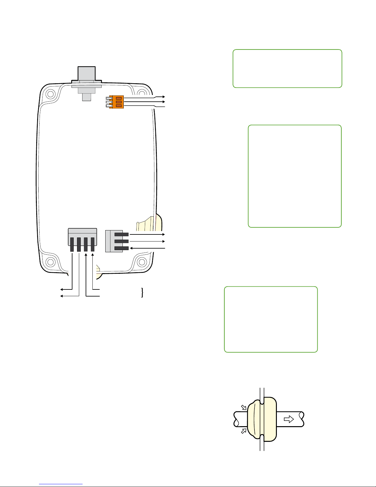
LumenRadio CRMX Slim User manual

RF Link
DMX
RD M
DALI
Coexistenceassured
Easy one-button operation. See
page 3 for details.
CRMX Slim receiver
CRMX Slim transmitter
quick start guide
Introduction
Thank you for buying a LumenRadio CRMX Slim product. This
guide is intended to give you a quick start to experience the
benets of LumenRadio’s CRMX system. The CRMX products
you just purchased are designed to give you the highest
reliability on the market and are fully compatible with other
CRMX products in entertainment lighting (CRMX Nova, CRMX
Outdoor, CRMX OEM). Through this you are able to expand
your wireless system with units from our other product lines
as well as with those of our partners. For the latest updates
please visit the LumenRadio website www.lumenradio.com.
We hope that you will enjoy our products and that they will bring
benets and positive experiences.
The information furnished in this start guide is for informational use only and is subject to change without notice. Please check www.lumenradio.com for latest version. LumenRadio AB assumes no responsibility or
liability for any errors or inaccuracies that may appear in this start guide. All information and graphics are property of LumenRadio AB, Svangatan 2B SE-416 68 Gothenburg, Sweden.
Notice
To optimize range and performance:
• Keep antennas upright
• Maintain TX to RX line of sight
• Elevate the units above any crowds
• Elevation above ground increases range
• Keep away from large metal objects

Connections
All connections are made via the two cable glands.
100-240VAC power input/output
Warning: Ensure that the supply is
de-energized before connecting,
disconnecting or whenever opening the
casing.
TIPS: The two grey connector blocks
can be detached from the circuit
board to assist with connections.
A loose two-way connector block is
also included to terminate the mains
ground input or to provide a ground
link through to the sensor power
connection (if used).
Cable size and type
Diameter = 8 - 13mm
Use stranded cable only
Power terminal connections
Max wire size = 1,5mm2 (16 AWG)
Min wire size = 0,08mm2 (28 AWG)
Min insulation strip length = 4 mm
DMX terminal connections
Max wire size = 0,5mm2 (20 AWG)
Min wire size = 0,08mm2 (28 AWG)
Insulation strip length = 5-6mm
DMX+
DMX-
Reserved for future upgrades
DALI out
Reserved for future upgrades
Neutral
Mains power in
Live in (100-240VAC)
Reserved for future upgrades
DALI out
GND
Correct use of the cable glands
When used correctly, the glands oer full environmental protection up to IP65.
1. Each gland has a
membrane inside it.
Puncture this using an
appropriate tool or the
cable itself.
3. Retract the cable
1cm, to ensure the IP
seal.
2. Insert the cable
through the gland,
with an additional
1cm of cable
than your desired
length.

RF Link
DMX
RD M
DALI
Coexistenceassured
Using SuperNova
The default DMX address for the DALI/DSI interface is channel 1. After a discovery in SuperNova the Slim receiver will appear as
two units, the actual Slim wireless module as well as the DALI/DSI interface. The start address of the DALI/DSI interface can be set
in SuperNova. SuperNova runs on any Windows, Mac OS X or GNU/Linux computer with a Java runtime environment of at least
version 1.6. The latest version of SuperNova as well as detailed user guides can be accessed at www.lumenradio.com/supernova.
Operation
CRMX Slim units can link with any other CRMX units as well as legacy W-DMX™ (G2/G3/G4) transmitters (2.4 GHz only).
To unlink
• Unlink one: On the receiver, press and hold
its button for more than 3 seconds to
unlink it from a transmitter. The RF Link
indicator will extinguish.
• Unlink all: On the transmitter, press and
hold its button for more than 3 seconds
to unlink all of its receivers.
To link
1. Ensure the antenna is connected.
2. Power on the transmitter and receiver(s).
3. Ensure that the RF Link indicators on all receivers are o to
indicate that the receiver(s) are ready to be linked. (If
necessary, follow the unlink procedure.)
4. On the transmitter, press and release the button.
5. The transmitter will search for any unlinked receivers. Its RF
Link indicator will ash for 10 seconds and normal operation
will resume.
6. The RF Link indicator will change to a steady on-state on
successfully linked receivers.
Specications
Power input: 100-240VAC / 50-60Hz
Maximum consumption: 3W
Operation temperature range: -20°C to +50°C (-4°F to 122°F)
Environmental: IP65 (protected from water jets)
Frequency range: 2.402 to 2.480 GHz
Output power levels: 300mW (25dBm) (Permitted only
in North America), 100mW (20dBm),
35mW (15dBm), 10mW (10dBm)
Order code CRMX Slim receiver: 800-5001/OS-RRX1
Order code CRMX Slim transmitter: 800-5101/OS-DTX1
Control panel
Status indicators
RF Link on Transmitter:
On = Normal operation.
Fast ashing (~3Hz) = Linking.
Slow ashing (~1Hz) = Unlinking.
RF Link on Receiver:
On = Linked with RF signal.
O = Unlinked.
Fast ashing (~3Hz) = Linking or linked,
but with lost RF signal.
DMX: On when DMX is present.
RDM: Flashes to RDM activity.
DALI: On when a DALI conversion is
active. Flashes when DALI data is being
sent.
Link button - press to link with, or
unlink from, another unit.
Signal quality indicators
Transmitter:
Not used/All o.
Receiver:
Top green = 80% signal
quality.
Mid green = 60% signal
quality.
Bottom green = 40%
signal quality.
Amber = 20% signal
quality.
Red = Link problem.
Firmware upgrade
All CRMX units are upgradeable. Please
contact your local distributor for more
information.

Mounting template (1:1)
152mm
TOP
156mm
13mm
11mm
11mm
Ø4mm
Ø4mm
Ø7mm
5mm
90mm
25.5mm25.5mm
174mm
LumenRadio AB, Svangatan 2B, SE-416 68 Gothenburg, Sweden • www.lumenradio.com
Phone: +46 (0)31 301 03 70 • Fax: +46 (0)31 301 03 80 • Email: suppor[email protected]
• Reorient or relocate the receiving antenna.
• Increase the separation between the equipment and receiver.
• Connect the equipment into an outlet on a circuit dierent from that to which the
receiver is connected.
• Consult the dealer or an experienced radio/TV technician for help.
Release 2.0 October 2013 In cooperation with Corporate Text & Design (www.ctxd.com)
FCC ID: XRSCRMXNOVA101
IC: 8879A-CRMXN101
SRRC CMIT ID: 2011DJ0708 US Patent 7,432,803
EU Declaration of Conformity
These products compliance with the Essential Requirements
of the R&TTE Directive of the European Union (1999/5/EC).
This equipment meets the following conformance standards:
ETSI EN 301 489-1 V1.8.1; ETSI EN 301 489-3 V1.4.1;
ETSI EN 300 328 V1.7.1; EN 609 50
FCC statement
Note: This equipment has been tested and found to comply with the limits for a Class B digital device, pursu-
ant to part 15 of the FCC Rules. These limits are designed to provide reasonable protection against harmful
interference in a residential installation. This equipment generates, uses and can radiate radio frequency energy
and, if not installed and used in accordance with the instructions, may cause harmful interference to radio
communications. However, there is no guarantee that interference will not occur in a particular installation. If
this equipment does cause harmful interference to radio or television reception, which can be determined by
turning the equipment o and on, the user is encouraged to try to correct the interference by one or more of the
following measures:
R001 - A
00019
Notice
Mount only in
upright orientation
as shown in this
drawing.
Table of contents
Other LumenRadio Receiver manuals