EBS CPX200NW User manual

EN
ALARM CONTROL UNIT
CPX200NW
User manual
Version of the manual: v1.5
Date of issue: 2015.04.08
Firmware version: 1.1.1
GPR transmitter configurator version: 1.3.45.23

CPX200NW ALARM CONTROL UNIT – U ER MANUAL 2 / 28
EN
DECLARATION OF COMPLIANCE
We, EB p. z o.o., declare with full responsibility that the present
product meets all requirements provided for in the Directive
1999/5/EC of European Parliament and Council dated 9 March 1999
The copy of the “Declaration of Compliance” can be found at
http://www.ebs.pl/en/certificates/ .
IMPORTANT INFORMATION
Crossed symbol of a trash bin means that at the territory of European
Union, the product, after finishing its useful life, shall be disposed of
in a separate, specially dedicated collection point. It refers to the
equipment itself and its accessories marked with that symbol. The
products shall not be disposed of together with non-sortable
municipal waste.
The content of the document is presented “as is”. The present document shall not be
deemed to be providing any warranties, either express or implicit, including but not
limited to, any implied warranties of merchantability or fitness for a particular
purpose, unless it is required by relevant law. The manufacturer reserves the right to
amend the present document or withdraw it any time, without notice.
The manufacturer of the equipment promotes the sustainable development policy. It
reserves the right to modify and improve any functions of the product described in
the present document without previous notice.
The availability of particular functionalities will depend on the software version of the
equipment. Details can be found at the nearest dealer of the equipment.
In no event, the Manufacturer shall be held liable for any loss of data or loss of
profits or any specific, incidental, consequential or indirect damages caused in any
way.

CPX200NW ALARM CONTROL UNIT – U ER MANUAL 3 / 28
EN
CONTENT:
1.
INTRODUCTION ........................................................................................................... 4
2.
CONTROL UNIT FUNCTIONS........................................................................................ 5
2.1.
FUNCTIONAL CHARACTERI TIC.................................................................................... 5
2.2.
ELECTRICAL CHARACTERI TIC ..................................................................................... 6
3.
KEYPAD SPECIFICATION ............................................................................................. 7
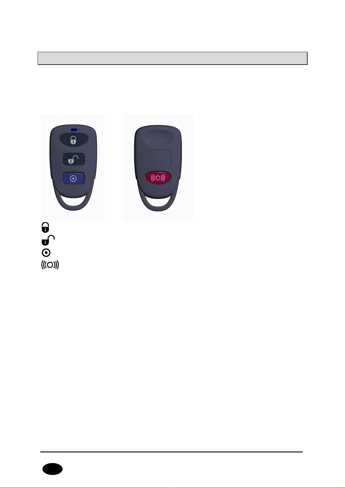
4.
REMOTE CONTROL SPECIFICATION .......................................................................... 10
5.
ARMING THE SYSTEM ................................................................................................ 11
5.1.
ARMING THE Y TEM .................................................................................................11
5.1.1.
ARMING FROM KEYBOARD ..................................................................................11
5.1.2.
ARMING FROM REMOTE CONTROL ......................................................................11
5.2.
ARMING THE Y TEM WITH FAULT .............................................................................11
.
DISARMING THE SYSTEM .......................................................................................... 13
6.1.
DI ARMING THE Y TEM ............................................................................................13
6.1.1.
DI ARMING FROM THE KEYBOARD......................................................................13
6.1.2.
DI ARMING FROM THE REMOTE CONTROL ..........................................................13
6.2.
ALARM DI PLAY..........................................................................................................13
6.3.
ALARM MUTE ..............................................................................................................13
7.
PARTITION HANDLING.............................................................................................. 14
7.1.
ARMING / DI ARMING WITH ELECTING PARTITION .................................................14
7.2.
QUICK ARMING / DI ARMING PARTITION ..................................................................14
8.
USER FUNCTIONS ...................................................................................................... 15
8.1.
ALARM MEMORY .......................................................................................................15
8.2.
FAULT MEMORY ........................................................................................................16
8.3.
ZONE BLOCKING.........................................................................................................17
8.4.
ADDING A NEW U ER .................................................................................................17
8.5.
U ER DELETE .............................................................................................................18
8.6.
CHANGE OF U ER CODE..............................................................................................19
8.7.
PROGRAMMING TIME..................................................................................................19
8.8.
PROGRAMMING DATE .................................................................................................19
8.9.
TEXT ME AGE .........................................................................................................20
9.
CHANGE HISTORY...................................................................................................... 28

CPX200NW ALARM CONTROL UNIT – U ER MANUAL 4 / 28
EN
1. INTRODUCTION
Thank you for choosing EB alarm control unit.
CPX200N is a simple, functional alarm control unit integrated with G M/GPR / M
transmitter, intended for small- and medium- sized facilities. The central unit is
equipped with 3 outputs and 7 wired and 9 wireless zones with the possibility to be
divided into 2 partitions. Dedicated KP16 LED keypad was designed in a modern,
discreet style. Portable size, large, comfortable buttons and simple installation
contribute to indisputable advantage of our system.
The product was designed in accordance with the requirements of PN-EN 50131
standards, grade 2, Environmental class II.

CPX200NW ALARM CONTROL UNIT – U ER MANUAL 5 / 28
EN
2. CONTROL UNIT FUNCTIONS
2.1. FUNCTIONAL CHARACTERISTIC
ZONES
•7 zones with the NC / NO / EOL-NC / EOL-NO / DEOL-NC / DEOL-NO
configuration possibility
•9 wireless zones
•Detection lines – instant, delayed, 24h burglary, arming/disarming,
24h tamper, interior delay, 24h burglary silent, 24h fire
PROGRAMMABLE OUTPUTS
•1 monitored alarm output, high-current (max. current 1.1A)
•2 monitored alarm outputs, low-current (max. current 50mA)
FEEDING OUTPUTS
•1 signalling device output (max. current 350mA)
•1 detector output (max. current 350mA)
•1 keypad output (max. current 100mA)
PARTITIONS
•2 partitions with the possibility to assign any number of zones to each of them
KEYBOARD
•cooperation with LED keyboard KP16
•ability to connect up to three keypads
TRANSMISSION
•Transmission of signals through GPR / M module.
•Encryption of data transfer using AE standard
•Communication with monitoring station using dedicated O M.2007 server that
ensures the reliability of data transfer thanks to a redundancy function.
•Control of G M/GPR connection – automatic restoration of connection with
monitoring station or switching to secondary server
CONFIGURATION
•Local, using KP16 keypad or a computer
•Remote through GPR , M or C D
USERS
•1 admin code (main)
•1 service code
•8 user codes
•Possibility to restrict the scope of authorisation to a few codes only
SYSTEM OPTIONS
•Automatic diagnosis of basic system components

CPX200NW ALARM CONTROL UNIT – U ER MANUAL 6 / 28
EN
•Possibility to review faults, alarm memories, event log
•ystem/technical event history up to 5000 events
2.2. ELECTRICAL CHARACTERISTIC
upply voltage: 18VAC (16-20VAC)
Required transformer Power: min. 20VA
Current consumption average/max:
(average measured@: fully charged battery,
established connection with server, connected
keypad, no sensors connected)
120mA / 1100mA @18VAC
Average current consumption; lack of
external supply (without keypad/ with
keypad):
(fully charged battery, no sensors connected,
established connection with server)
60mA / 80mA
Charging current:
(measured with totalny discharged battrey)
max. 350mA
Charging voltage: 13.8V
upported bartery type: Lead-acid 12V
Low voltage – event treshold: 11V
Voltage battery cut off level: below 9V
Working temperature: -10ºC to +55ºC
Working humidity: 5% to 93%
PCB dimensions: 152mm x 78mm x 30mm

CPX200NW ALARM CONTROL UNIT – U ER MANUAL 7 / 28
EN
3. KEYPAD SPECIFICATION
Power supply voltage: 10 – 13.8 VDC
Power consumption: typ. 20 mA, max. 80 mA
Keypad weight: 70 g
Size of casing: 99 x 82 x 19 mm
Keypad type: LED, 16 status LEDs, 4 mode LEDs (ALARM, ARMED,
Y TEM, PROG)
Button layout: tandard telephone keypad 3 x 4 buttons
Drawing 1. KP1 Keypad

CPX200NW ALARM CONTROL UNIT – U ER MANUAL 8 / 28
EN
1. Keypad buttons
0-9 buttons and * as well as # are intended for the keypad and alarm control
unit operation. After first pressing any button, the keypad is backlit. After a few-
second idle time, backlight gets automatically dimmed. In order to make codes
easier to remember, buttons are marked with the alphabet.
2. ALARM LED (red):
Flashing light – means that alarms occurred in the system (alarms memory).
Constant light – means that system is in alarm state.
Off – system is operating correctly.
3. ARMED LED (red):
Flashing light – means that time for leaving any of the partitions is counted.
Constant light – at least one partition is armed
Off – partitions disarmed.
4. SYSTEM LED (yellow):
Flashing light - means that in the control unit’s memory there are faults that has
already ceased (there was power loss, but it has already restored).
Constant light – there is a fault in the system that was not removed.
Off – no fault in the system.
5. PROG LED (blue):
Flashing slowly – service function is activated and it is one of the user functions.
Flashing – data will be entered.
Constant light – installer service function is activated.
. 1 – 1 LEDs (red)
When LED goes on during normal operation, it means the line it is assigned to
was disrupted. Flashing LED means the zone was interlocked. After activating
service functions, LEDs display data.
7. Screwed Connectors
Connectors for connecting cables joining the keypad with the alarm control unit.
8. Cable Entry
It is a place for entering the connection cables.
9. Assembly Holes
The keypad was equipped with four round assembly holes for proper fastening
the keypad.

CPX200NW ALARM CONTROL UNIT – U ER MANUAL 9 / 28
EN
10. Casing Opening Latch
To open the casing it is recommended to use flat 2.5-5mm screwdriver. Insert it
slightly in indicated hole and perform slight lever movement toward the rear side
of the casing.
11. Anti-Sabotage Switch
After the keypad is assembled the switch contact is closed. Unauthorised
disassembly of the keypad will send the message to the alarm control unit. In
order to eliminate surface unevenness, a spring is located on the switch lever.

CPX200NW ALARM CONTROL UNIT – U ER MANUAL 10 / 28
EN
4. REMOTE CONTROL SPECIFICATION
Frequency: 433.92MHz
Coding: Keeloq code hopping
Number of buttons: 4
Battery: Varta Li-Mn 3V type CR2032
- ARM button
- DI ARM button
- ILENT ALARM button
- ALARM button

CPX200NW ALARM CONTROL UNIT – U ER MANUAL 11 / 28
EN
5. ARMING THE SYSTEM
5.1. ARMING THE SYSTEM
5.1.1. ARMING FROM KEYBOARD
1. Enter your code and press . 3 beeps will confirm the code.
Note: If incorrect code is entered the keypad will emit long
constant sound. Repeat the arming process by entering the
correct code.
2. Leave the facility before the time for leaving expires. That state is indicated
by intermittent sound and quick flashing the ARMED LED on the keypad until
the system gets fully armed. If the chirps are activated the arming will be
confirmed by one chirp of siren.
Note: If the partition is not plugged to any zones, the
partition is not armed.
5.1.2. ARMING FROM REMOTE CONTROL
Press the remote control buton indicated by the closed padlock symbol ,
assigned to the arming function. Keyboard confirms arming by lighting ARMED
LED. If the chirps are activated the arming will be confirmed by one chirp of
siren.
Note! The control panel allows you to assign remote control buttons to various
functions. It is possibile to configure different arming button.
5.2. ARMING THE SYSTEM WITH FAULT
If during the arming any faults are present in the system, the keypad will indicate it
with flashing ARMED and Y TEM LEDs and long constant audio signal. LEDs 1 to 8
will indicate which system errors are present. That state will maintain for 10 seconds.
If there is no possibility to quickly remove faults, press to arm the system.
Pressing will cancel the arming process.
Note: Remove the causes of faults as soon as possible.
Error codes:
1 – Damage or disruption of detector

CPX200NW ALARM CONTROL UNIT – U ER MANUAL 12 / 28
EN
2 – Damage of signalling device or signalling device active
3 – Damage of internal connection or sabotage
4 – AC power supply damage
5 – Battery damage
6 – AT damage
8 – Other damages

CPX200NW ALARM CONTROL UNIT – U ER MANUAL 13 / 28
EN
. DISARMING THE SYSTEM
.1. DISARMING THE SYSTEM
.1.1. DISARMING FROM THE KEYBOARD
1. Enter the facility through the entrance door. Intermittent sound and slow
flashing of ARMED LED on the keypad will remind of the need to disarm the
system before the delay time for entrance expires.
2. Enter the code and press . 3-tone beep of the keypad will confirm the
correct code input. The partition the user has access to will be disarmed. If
the chirps are activated the disarming will be confirmed by two chirps of siren.
If the user has access to all partitions, all of them will be disarmed. If there is
no armed partitions in the system, ARMED LED will be deactivated.
3. The system can be also disarmed in different way- by changing the partition
state. ee item 6. PARTITION HANDLING.
4. When system is disarmed, alarm will be muted (deactivated).
Note: Incorrect code will be indicated with a long constant
sound. Enter the correct code immediately and press .
.1.2. DISARMING FROM THE REMOTE CONTROL
Press the remote control buton indicated by the open padlock , assigned to
the disarming function. Keyboard confirms disarming by blanking ARMED LED. If
the chirps are activated the disarming will be confirmed by two chirps of siren.
Note! The control panel allows you to assign remote control buttons to various
functions. It is possibile to configure different disarming button.
.2. ALARM DISPLAY
If red ALARM LED flashes when the system is armed, it means that while you were
absent some alarms occurred (numbers of lines that initiated them will be displayed
as well) which have already ceased. But, if ALARM LED emits constant light, it means
that system still is in alarm state. Exercise caution! If you suspect any intruder to be
present in the facility, leave the facility immediately and call security guards.
.3. ALARM MUTE
1. To mute (deactivate) the alarm, enter the code and press . 3 beeps will
confirm the code. Also, the system will be disarmed.
2. In order to identify the alarm type, please refer to ALARM MEMORY chapter
of the present manual.

CPX200NW ALARM CONTROL UNIT – U ER MANUAL 14 / 28
EN
7. PARTITION HANDLING
7.1. ARMING / DISARMING WITH SELECTING PARTITIONS
1. Enter the number of the function and confirm using . Then enter
the user code and press . 3-tone beep will confirm the correct code
input.
Note: If incorrect code is entered the keypad will emit long
constant sound. Enter the correct code once again.
2. LEDs 1 and 2 will display the current partition state. LED on – partition armed,
LED off - partition disarmed. Only LEDs indicating the partitions the user has
access to will be on.
3. To change the partition state press buttons with partition numbers (LEDs with
relevant partition number will go on/off). Confirm the change of partition state
using button. 3 beeps will confirm the change. To cancel the entered
changes, press .
4. If partition arming was selected, the keypad will indicate counting the time for
leaving the facility. Leave the facility before the time for leaving expires.
After it is armed the ARMED LED will be constantly on.
5. If partition disarming is selected, the relevant partition will be immediately
disarmed.
7.2. QUICK ARMING / DISARMING PARTITIONS
1. Enter the number of the function ( for partition one or
for partition two) and confirm using . Then enter the user code and press
. 3-tone beep will confirm the correct code input.
Note: If incorrect code is entered the keypad will emit long
constant sound. Enter the correct code once again.
2. If partition arming was selected, the keypad will indicate counting the time for
leaving the facility. Leave the facility before the time for leaving expires.
After it is armed the ARMED LED will be constantly on.
3. If partition disarming is selected, the relevant partition will be immediately
disarmed.

CPX200NW ALARM CONTROL UNIT – U ER MANUAL 15 / 28
EN
8. USER FUNCTIONS
8.1. ALARMS MEMORY
- Display of alarms memory
The function displays the history of alarms that occurred in the system. When the
function is activated, ALARM and PROG LEDs are flashing slowly and all alarms that
occurred since last arming are displayed. LEDs 1 - 16 display the information from
which zones the alarm was activated. To clear the alarms memory, press . To
exit without clearing the alarms memory, press .
Alarm source types:
Diodes 1 to 16 – abotage of lines 1 to 16
If no diodes are on and the ALARM led is blinking, then there alarms that were
triggered by the source other than input lines.
Other alarms
history can be accessed
by selecting following code from the main menu: .
After pressing the button corresponding to active LED, the detailed information about
the alarm source within selected type is displayed.
Pressing will result in return to the main menu.
Other alarm source types:
2 – Keypads tamper
4 – Remote control alarm
Other alarm source types -> Keypads tamper:
1 – Keypad tamper 1
2 – Keypad tamper 2
3 – Keypad tamper 3
Other alarm source types -> Remote control alarm:
5 – KEELOQ remote control alarm
Note: Alarms memory is cleared after the system is armed.

CPX200NW ALARM CONTROL UNIT – U ER MANUAL 16 / 28
EN
8.2. FAULTS MEMORY
- Display of faults memory
The function displays the faults that are present in the system. When the function is
activated, Y TEM and PROG LEDs are flashing slowly and all faults that are
currently present in the system are displayed. Led 1 – 8 display information on the
cause of fault. To clear the faults memory, press . To exit without clearing the
faults memory, press .
Faults description:
1 –
Sabotage of zones
To display more detailed information about sabotage of zones, press
button.
1 – abotage of zone 1
2 – abotage of zone 2
16 – abotage of zone 16
To return to the main fault menu, press .
2 –
Fault of outputs 1 - 3
To display more detailed information about fault of outputs, press
buton.
1 – Fault of output 1
2 – Fault of output 2
3 – Fault of output 3
To return to the main fault menu, press .
3 –
Fault of feeding outputs
To display more detailed information about fault of feeding outputs, press
button.
1 – Fault of feeding output + KP
2 – Fault of feeding output +AUX1
3 – Fault of feeding output +AUX2
To return to the main fault menu, press .
4 –
AC fault
No more detailed information.
5 –
Battery fault
No more detailed information.
–
ATS fault
No more detailed information.

CPX200NW ALARM CONTROL UNIT – U ER MANUAL 17 / 28
EN
7 – Other damages
To display more detailed information about other damages, press
button.
1 – Clock fault
2 – Fault of central unit settings
3 –
Keypads tamper
To display more detailed information about keypads tamper, press
buton.
1 – Keypad tamper 1
2 – Keypad tamper 2
3 – Keypad tamper 3
To return to the
Other damages
, press
button.
4 – Low battery for wireless detectors (zones 8-16)
To return to the main fault menu, press .
8.3. ZONE BLOCKING
The zone blocking function allows de-activating stand-by mode of any zones or
bypassing any damaged lines. Also, zones which are not in stand-by mode and
which the user has access to can be blocked. Zones remain blocked until de-arming.
ystem informs the user about that fact with quickly flashing LED marked with the
number of the blocked zone.
Zone blocking:
1. Enter the number of the function and confirm with . Enter the
user code and press . 3-tone beep will confirm the correct code input.
Note: If incorrect code is entered the keyboard will emit long
constant sound. Enter the correct code once again.
2. Use buttons numbered 1 to 9 to select zones you want to block. electing
zone 10 to 16 can be achieved by pressing and holding for 2 seconds the
buttons 0 to 6 (0 for 10, 1 for 11, 2 for 12, etc.)
3. Change the zones blocking status by pressing numbered buttons (LEDs with
relevant zone number will go on/off). Press to confirm blocking of
selected zones. 3 beeps will confirm the change. To cancel the entered
changes, press .
8.4. ADDING A NEW USER
You can add a new user code here. New codes can be added by the administrator
only. 3 beeps will confirm the successfully entered function. Default admin code:
1111.

CPX200NW ALARM CONTROL UNIT – U ER MANUAL 18 / 28
EN
Note: Individual code cannot be the same; if any code is the
same as another one, it will not be recorded.
To add a new user:
1. Enter the function code and press to confirm.
2. Enter the admin code and confirm it with . 3 beeps will confirm the
correct code input.
3. Numbers of already existing users will be displayed.
4. Enter the ID of newly added user (1 to 8), other than already added ID
numbers, and press to confirm. Numbers of partitions a new user can
have access to will be displayed.
5. To activate/deactivate LED of an appropriate partition, press 1 or 2. When
the access is set, press to confirm. All LEDs shall be off now.
6. Enter the code of a newly added user (4 to 7 digits) and press to
confirm.
7. Enter the code of a newly added user again and press to finish adding
or to exit without saving changes.
8. uccessful adding a new user will be confirmed with 3 beeps, otherwise a
constant sound will be emitted.
8.5. USER DELETE
You can delete a user here. Codes can be deleted by the administrator only. 3 beeps
will confirm the successfully entered function. Default admin code: 1111.
Note: You cannot delete Admin account (user no. 0) and
Installer account (user no. 9)
To delete a user:
1. Enter the function code and press to confirm.
2. Enter the admin code and confirm it with . 3 beeps will confirm the
correct code input.
3. Numbers of already existing users will be displayed.
4. Enter the ID code (1- 8) of a user to be deleted and press to confirm or
to exit without saving changes.
5. uccessful deletion of a user will be confirmed with 3 beeps, otherwise a
constant sound will be emitted.

CPX200NW ALARM CONTROL UNIT – U ER MANUAL 19 / 28
EN
8. . CHANGE OF USER CODE
The user can change its code here. 3 beeps will confirm the successfully entered
function.
<User code >
<Code> <Code>
where:
User code -
Code of a user changing the password
Code –
New access code
(from 4 to 7 digits)
In any moment you can press to exit without saving changes.
8.7. PROGRAMMING TIME
You can change system time here. Time can be changed by the administrator only.
3 beeps will confirm the successfully entered function. Default admin code: 1111.
< Administrator code > <hh> <mm>
where:
Administrator code
– Administrator code.
hh
– Hours.
mm
– Minutes.
In any moment you can press to exit without saving changes.
8.8. PROGRAMMING DATE
You can change system date here. Date can be changed by the administrator only.
3 beeps will confirm the successfully entered function. Default admin code: 1111.
< Administrator code > <YY> <MM> DD>
where:
Administrator code
– Administrator Code.
YY
– Year.
MM
– Month.
DD
– Day.
In any moment you can press to exit without saving changes.

CPX200NW ALARM CONTROL UNIT – U ER MANUAL 20 / 28
EN
8.9. TEXT MESSAGES
CPX200NW Alarm Control Unit can be managed by text messages. User can use a
variety of texts that can be send to the device in order to configure it or poll its
status. For M to be accepted, the phone number from which the text is being
send, has to be enlisted on the allowed numbers list. CPX200NW can store up to 10
phone numbers and up to 32 text messages. If, for any reason, the M can not be
send at the moment, it will be send as soon as the connection with the G M network
is re-established but not later than 1 day after the occurrence of the event triggering
M send request (text messages get expired and are deleted). Message should
contain only characters from English alphabet. Furthermore, if the text contains any
spaces, content of the message, starting from the equation mark (=) till the end of
the message, should be enclosed in quotes (" ").
Descriptions of messages handled by the unit are listed below:
Acquiring the state of partitions
Command syntax XXXX GETARMED
Command description Acquiring the information which partitions are
armed/disarmed
XXXX – user code
Example: 1234 GETARMED
Feedback message PARTITION1:X, PARTITION2:Y
or
GETARMED:ERROR
Feedback message
description
PARTITION1:X, PARTITION2:Y – Information about
partitions arm/disarm state.
PARTITION1,PARTITION2 – default partitions names,
they can be changed with the ETNAME command
X,Y – partition states, possibile values:
0 – disarmed
1 – armed
GETARMED:ERROR – command rejected by the
system
Table of contents
Other EBS Control Unit manuals